Week - 4 - Crash Box Simulation
Objective of the challenge: To conduct a crash test of the crashbox modelled as a rectuangular channel which can thought of as the most simple crashbox using a shell body which is made to hit a rigid wall by selecting appropriate rigid wall option from the manual.
Unit System: g-mm-ms
Keywords used for preprocessing:
There are totally 9656 shell elements in the part which are connected by 9792 nodes
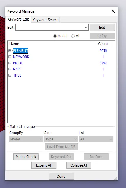
The following Keywords have been use to preprocess in the model
1) Element Formulation
*ELEMENT_SHELL: Shell element which connects the Node ID's of the crash box.
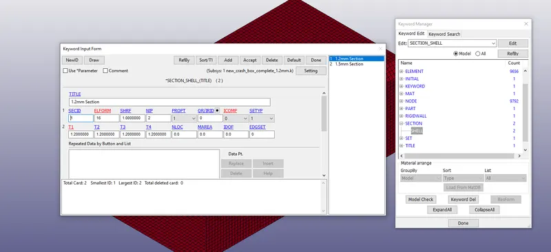
*SECTION_SHELL: The section shell was used to model the plate whose thickness was taken to be 1.2mm and another shell element of 1.5mm. The element formulation was taken to be as type 16 for both types inorder to prevent hourglassing. All other parameters in the keyword card was kept constant.
2) Material of the crashbox
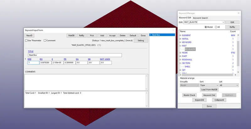
*MAT001 Elastic: This material used for the crashbox was steel as indicated in the challenge whose properites was defined as density as 0.00783 `g/(mm^3)`Young Modulus as 2.1x`10^5`GPa and Poisson ratio as 0.3
3) Part Definition
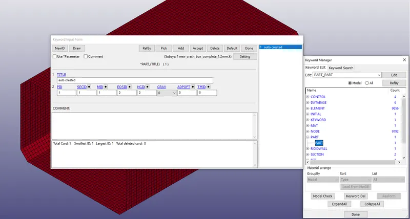
*PART : This keyword is used to link the sections and materials which are defined using *SECTION and *MAT by linking SECID to *SECTION and MATID to *MAT
4) Initial velocity for the crash box
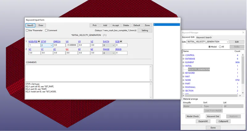
*INITIAL_VELOCITY_GENERATION: Using this keyword the velocity of the ball was taken to be 13.89mm/ms in the negative x-axis where the rigid wall is created and hence VX =-13.889mm/ms. Using Set Type as 2. the PID is chosen to be the crashbox part id which is 1
5) Rigidwall modelling
By referring the volume 1 keyword manual, we search various options for *RIGIDWALL and the appropriate option was chosen to be *RIGIDWALL_PLANAR
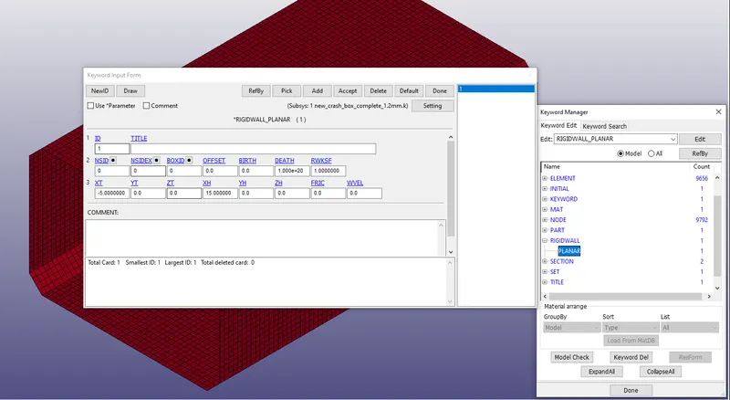
Here XT is the x-coordinate of tail of an outward drawn normal vector which is taken to be -5mm and XH is=x-coordinate of head of normal vector which is taken to be 15mm. It is to be noted the normal of the rigid plane should be pointed towards the crashbox model. The direction of outward normal of the part and the rigid wall should be towards each other.
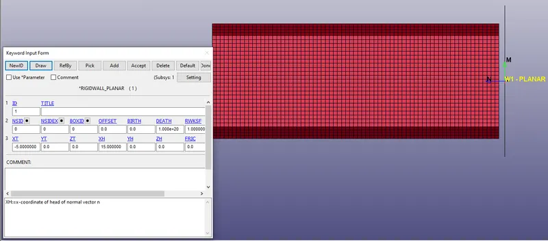
Remaining all the parameters in this option was kept constant
6) Control cards
Different control cards like *CONTROL_ENERGY for all global energy considered during the analysis were activated for calculation.
*CONTROL_TIMESTEP : this card was initialized and all parameters are kept default
Finally the *CONTROL_TERMINATION was used to set the end time of the simulation to 1.1ms.
7) Output generation
Different ouput files were written using *DATABASE_ASCII_option. Some of them includes GLSTAT, RCFORC, SLEOUT, SECFORC These files are read at a time duration each of 0.01ms
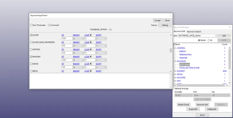
The animation file was written using *DATABASE_BINARY_D3PLOT option to study the response for 0.01ms each.
*DATABASE_CROSS_SECTION_PLANE :
A cross-section plane was created to study the cross-section forces at the middle of the crashbox along its length. The parameters from the cross section plane is found out by activating the SECFORC option in *DATABASE_ASCII option.
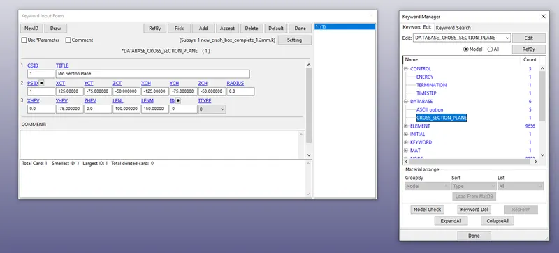
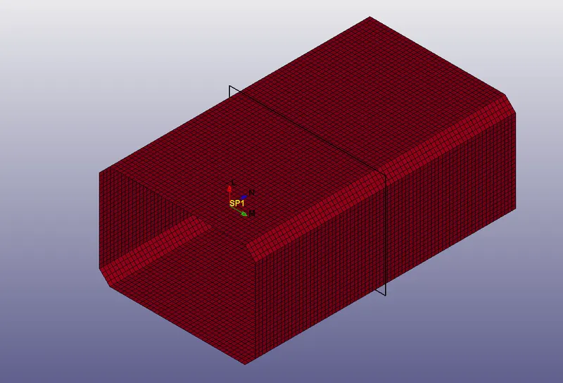
The solving methodology used was Explicit Analysis Method
The same steps were followed for the shell thickness of the crashbox which is 1.5mm
Results:
The results are summarized for shell thickness of 1.2mm.
1) GLSTAT
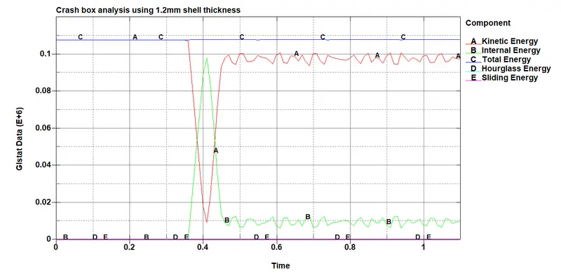
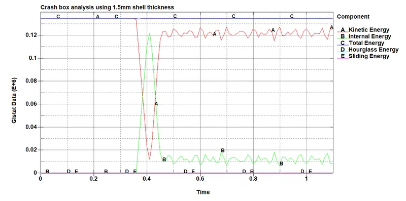
The global energy results of the complete system from both the cases have been plotted It is seen that by keeping all the factors same, all the energy plots shift upwards which means that there is increase in magnitude as the thickness of the box crashbox increases. The magnitude of hourglass energy was well below the minimum value, which shows it contributes very less to the total energy. The total energy of the system remains constant.
2) MATSUM
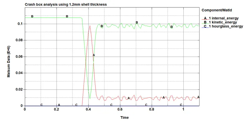
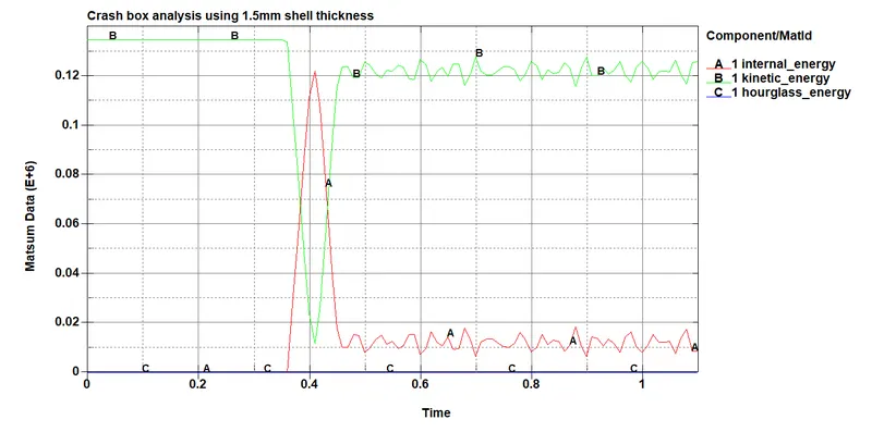
The individual energy results of the crashbox from both the cases have been plotted It is seen that by keeping all the factors same, all the energy plots shift upwards which means that there is increase in magnitude as the thickness of the box crashbox increases. The magnitude of hourglass energy was well below the minimum value, which shows it contributes very less to the total energy
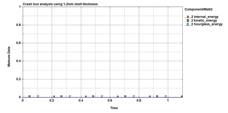
In the case of rigidwall since the wall is termed 'rigid', it doesn't contribute to change in deformation or change in energy an hence the graphs are zero in magnitude.
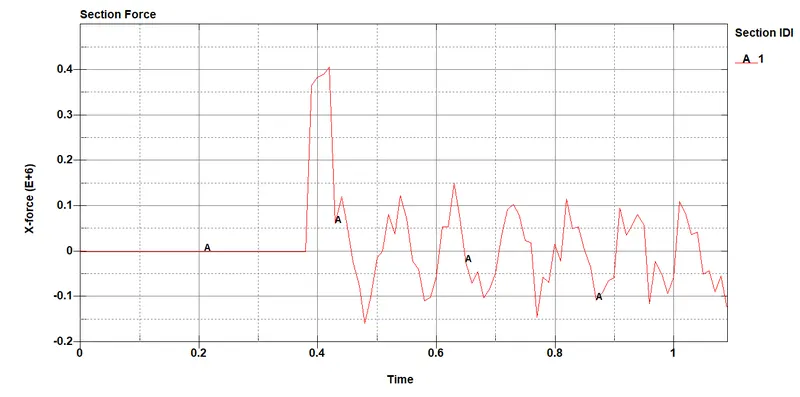
- Cross-sectional force generated in the middle of the crashbox (along its length)
3) SECFORC
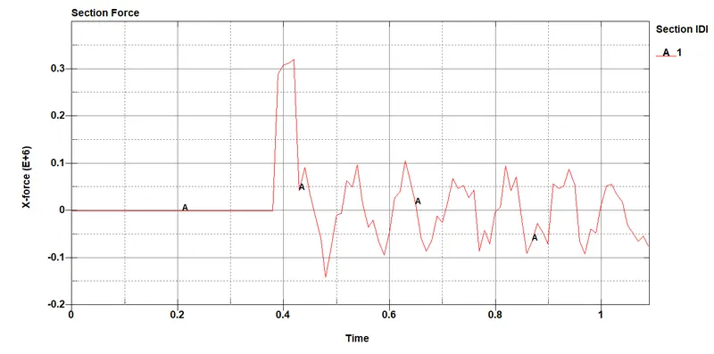
The above plot is the section force for the crashbox in the x direction. Since the box is crashing in the rigid wall along the x-axis for that reason the X-force is plotted. This graph is plotted for a thickness of 1.2mm
 The X- axis force is plotted for a thickness of 1.5mm
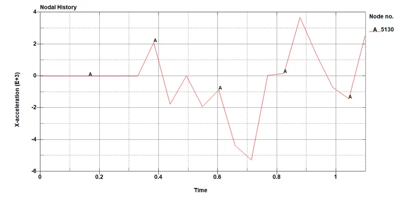
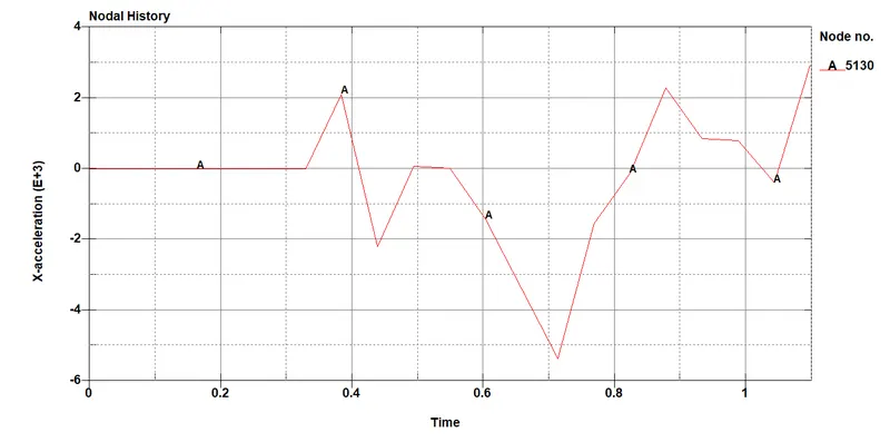
- Acceleration plot of a node in the middle of the crashbox (along its length)
For 1.2mm thickness
For 1.5mm thickness
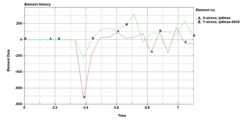
- Maximum directional stress and strain along the length of the crashbox (X strain, Y strain etc)
For 1.2mm thickness of the box
For 1.5mm thickness of the box
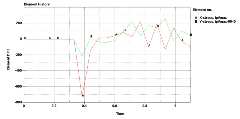
For 1.2mm thickness of the box
For 1.5mm thickness of the box
Conclusion:
1) With the increase in thickness of the crashbox, we find that the global energies of the system increases.
2) The section force also increases wih the thickness of the crashbox from 1.2mm to 1.5mm.
3) The acceleration and elemental stress/strain plots are shown for both the thickness of the crashbox.