Week - 5 - Modelling Spotwelds
Objective of the challenege: To model spotwelds for the given assembly of parts and run a crash test. Two separate instances of the spotwelds should be modeled: one using beam elements and the other using solid elements separately
Unit System: g-mm-ms
Number of spotwelds used for this challenge: 3
There are 3 beam elements, 10014 shell elements connected by 10296 nodes
I. Spotweld using beam elements
In this case, we construct spotwelds using the Element generation icon present on extending the toolbars after clicking the Mesh icon. We select the beam option present in the element generation dialog box and make the beam element by clicking on the drop down adjacent to "Beam By:" and selecting Two Node Sets.
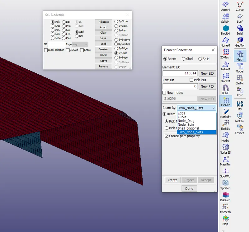
Next we look for wireframe mode in the bottom toolbar and convert the default view to wireframe mode and further select two nodes using Pick Node set -1 and Pick Node set -2, one from the red plate and the other from the blue plate respectively and click create and further click accept.
The beam element gets created.
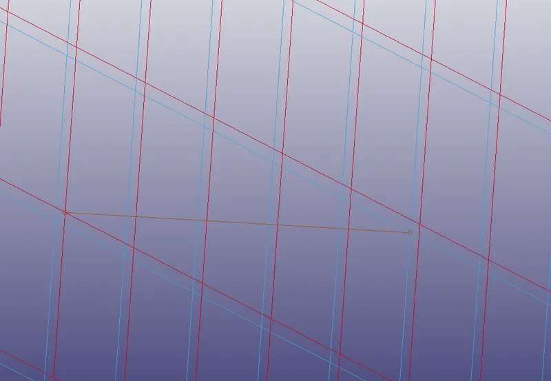
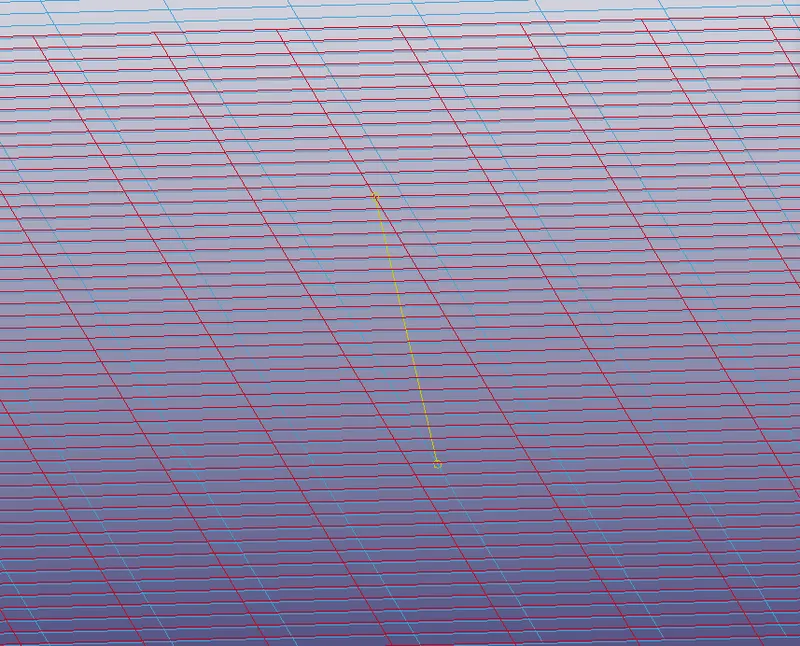
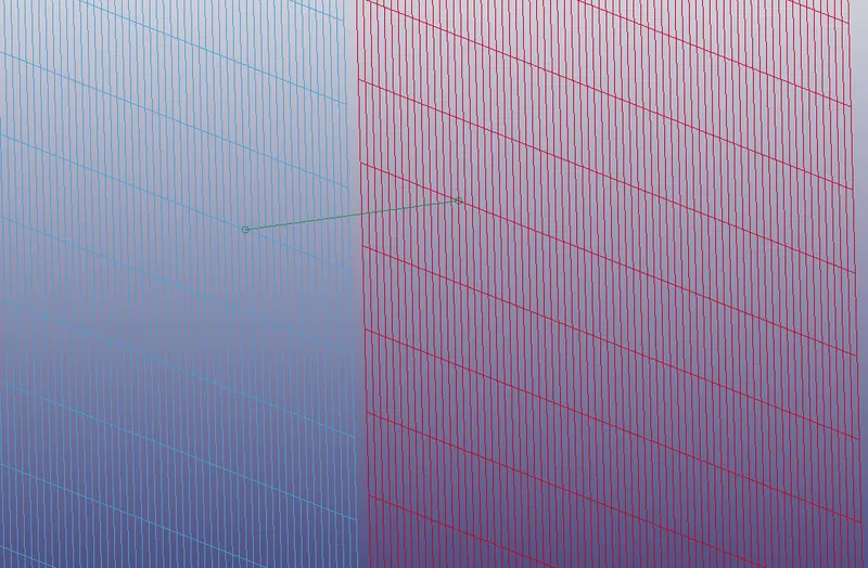
In this way, we can also follow the same process for two other beam elements.
1) *SECTION
- Shell
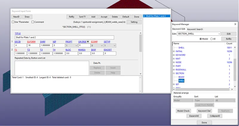
The two plates are modelled using shell elements whose thickness are taken to be 1.5mm. Eleform type 16 which is fully integrated shell element is used to prevent the occurence of hourglass effects.
- Beam
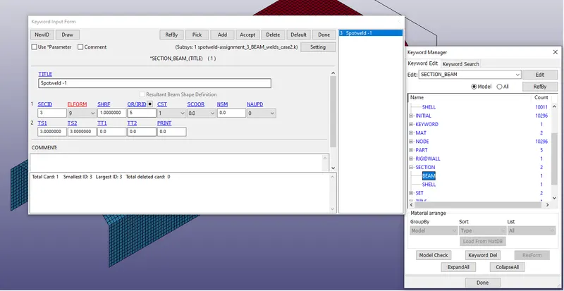
The beam elements are modelled using spotweld beam of elform type 9 and considering the thickness of 3mm in the s-direction of the beam.
2) *MAT
- Elastic (001)
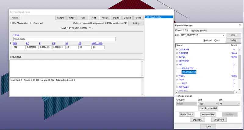
The plates are modelled using elastic material type and the material considered is steel for this purpose. The density is considered to be `rho`=0.00789 `frac{g}{mm^3}` Elastic Modulus is taken to be `E=2.1`x`10^5 GPa` and Poisson ratio `nu=0.3`
- Spotweld (100)
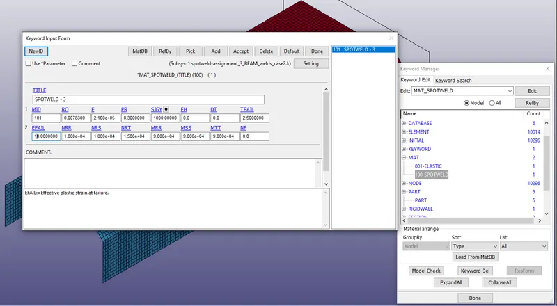
Since beam are modelled as spot welds between plates The beams are modelled using separate spotweld material type and the material considered is again steel for this purpose. The density is considered to be `rho`=0.00789 `frac{g}{mm^3}` Elastic Modulus is taken to be `E=2.1`x`10^5 GPa` and Poisson ratio `nu=0.3`.
In addition to these parameters, the failure rate of spotweld material is also mentioned using TFAIL. The effective plastic strain at failure is considered as 10% . The different force resusltants at failure are taken as orders of power four.
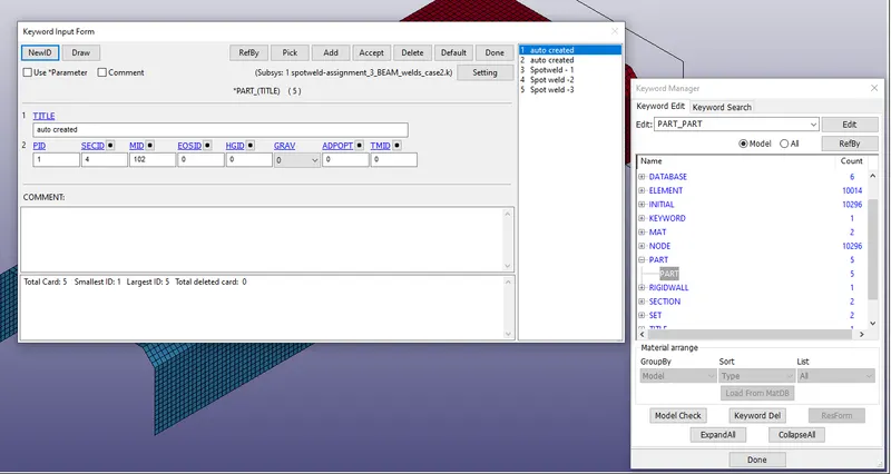
3) *PART
The part keyword is used to connect each part which in this case is the plates and spotweld beams in the workspace with their appropriate section ID's and Mat ID's respectively.
4) *RIGIDWALL
Since the objective is to perform a crash analysis in this challenege, we need to model a rigidwall in this case and hence use the rigidwall_planar option from the list of available options.
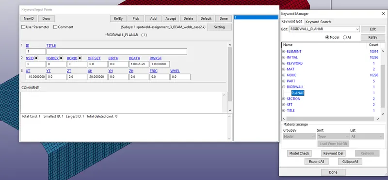
XT which is the x-coordinate of tail of normal vector and is taken to be -10mm and XH is the coordinate of head of normal vector as 20mm. Ensuring that the normal of the rigidwall and face towards the plates
5) *INITIAL
- Velocity_Node
The velocity of the plates are set to VX= -13.889mm/ms since the plate is moving in the negative x-axis crashing towards the rigidwall
6) *CONTACT
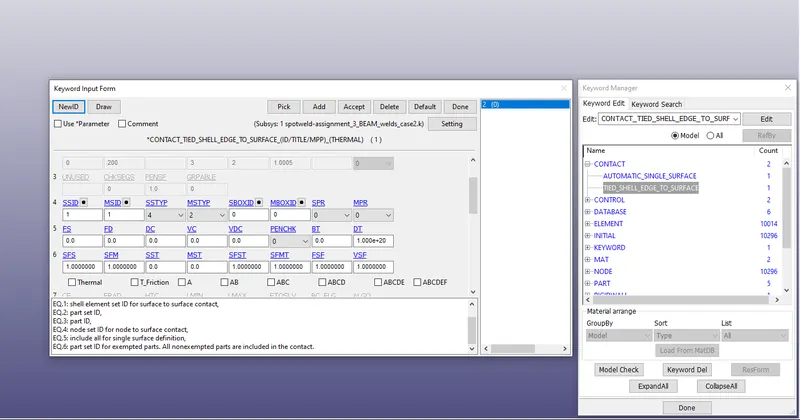
- Tied nodes to surface
In this definition we chose the spotweld beam as the slave set and the plates as the master set by chosing STYPE as 4 which is node set ID for node to surface contact and MTYPE as 2 which is part set ID
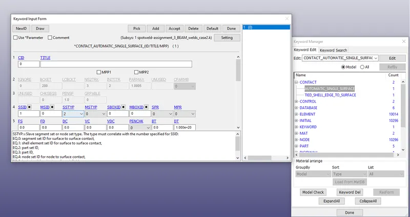
- Automatic Single surface
For the contact of two plates we use the automatic single surface, so as to accoiunt for contact after the spotweld fails.
7) *CONTROL
- Termination: The time for termination is chosen to be 5ms to study the after effect once the crash happens.
- Energy: The *control_energy option is activated so as to consider all the energy in the analysis.
8) *DATABASE
- Binary D3PLOT: This option is called for output of the animation file for every 0.1ms
- History node: This option gathers all the information related to a particular node.
- ASCII files : We will use this option for calling GLSTAT files and SWFORC files
II. Spotweld using solid elements
In this case, we construct spotwelds using the Element generation icon present on extending the toolbars after clicking the Mesh icon. We select the solid option present in the element generation dialog box and make thespotweld solid element by clicking on the drop down adjacent to "Solid By:" and selecting Solid face drag.
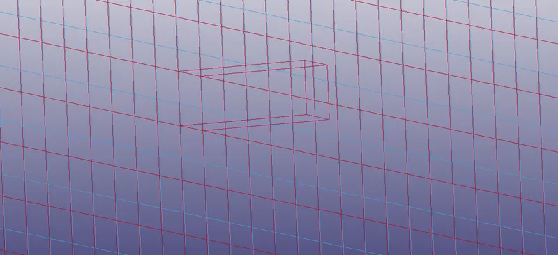
Next we look for wireframe mode in the bottom toolbar and convert the default view to wireframe mode. We select the required element on which the spotweld has to be made from the red plate and set the coordinate of the point on which the direction of the solid element would be generated. In addition we also give the required thickness and number of segments as 1 for making one solid element.
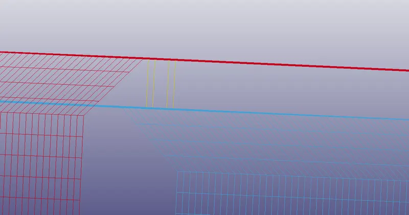
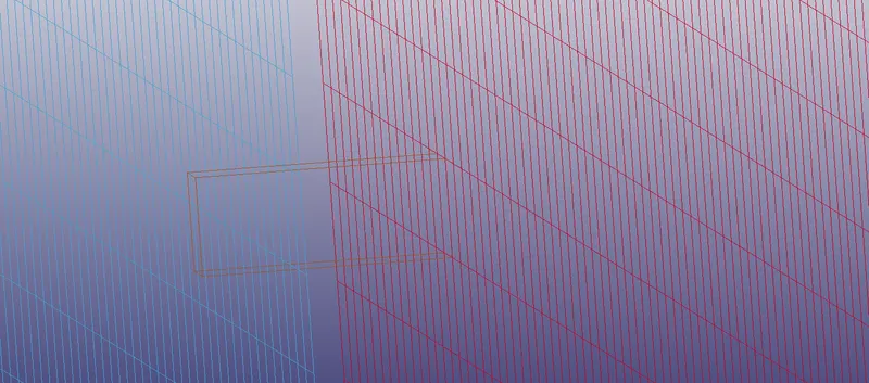
We further click on create and accept and click on done
1) *Section
- Solid
For this case since we have modelled the spotweld as solid element, we use a *section_solid for formulating the element by using the element formulation type 1 for spotweld material.
The plate is modelled as a shell element and the steps are same as in the case of beam material for spotweld.
2) *Contact
- Spotweld
In this definition we chose the spotweld solid as the slave set and the plates as the master set by chosing STYPE and MTYPE as 2 which is part set ID
The remaining procedure used for material for plates and spotwelds remain same for plates and spotweld solid respectively. The definitions for control, initial, rigidwall, database are exactly similar to the above steps
OUTPUT
1) GLSTAT
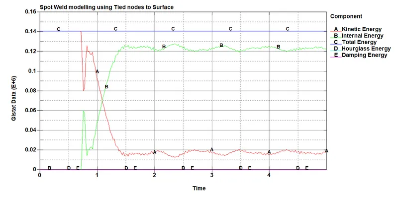
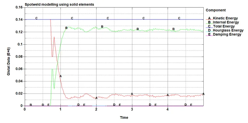
From the Global statistics of energies plot it is seen that the magnitude of the energy of the system remains constant in both the cases of spotweld modelling. The total energy of the system is also constant in both the cases.
2) SECFORC
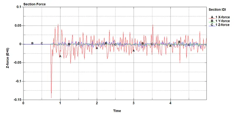
Section force graph using beam element to model spotweld
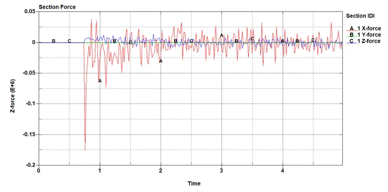
Plot of section force using solid element to model spotweld
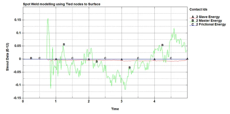
3) SLEOUT
- Automatic tied nodes to surface plot
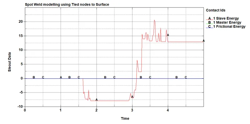
- Single surface to surface contact
4) SWFPRC
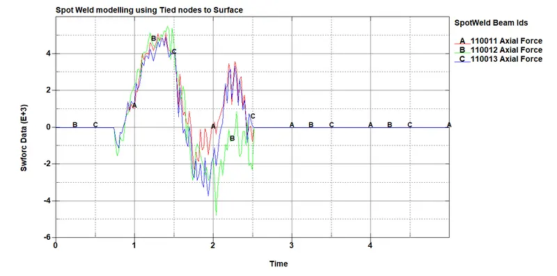
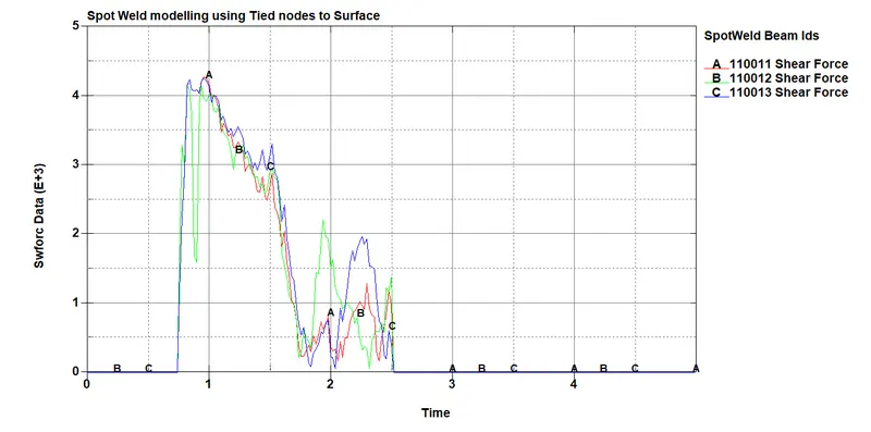
Comparing the axial force and shear force for the three spotwelds using beam elements in the simulation
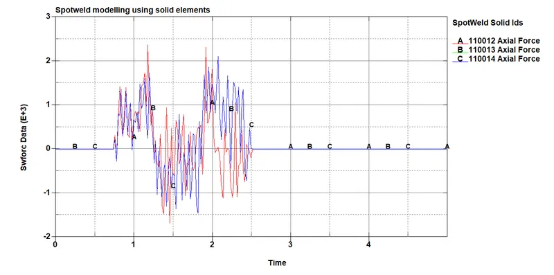
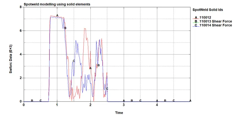
Comparing the axial force and shear force for the three spotwelds using solid elements in the simulation
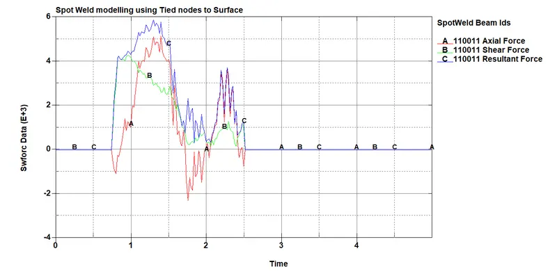
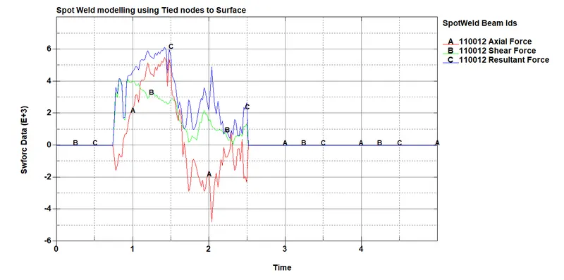
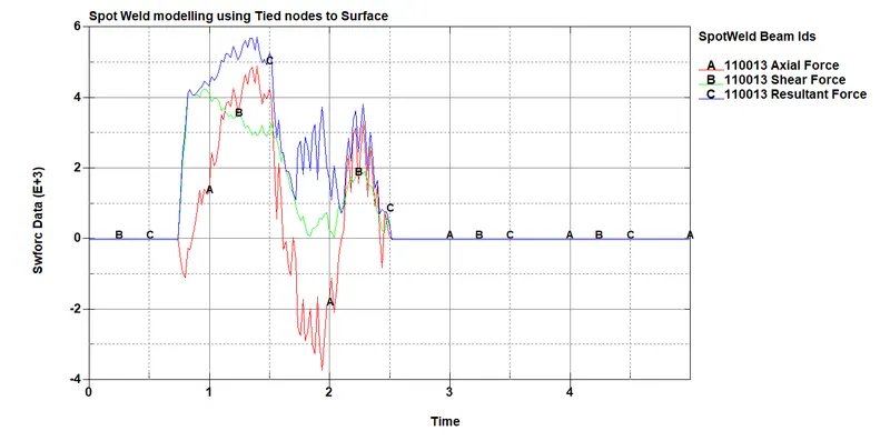
Comparing the different forces for the beam modelled spotwelds used in the simulation
5) Nodal acceleration
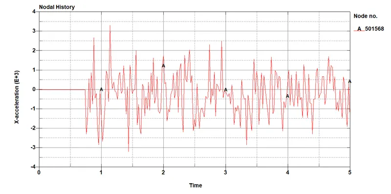
Nodal acceleration plot for beam spotweld
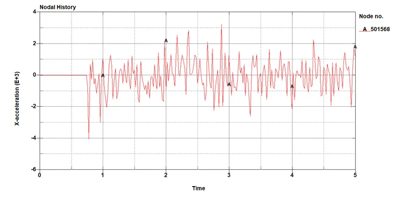
Nodal acceleration for solid spotweld element
6) Elemental stress and strains
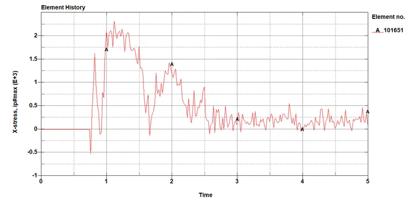
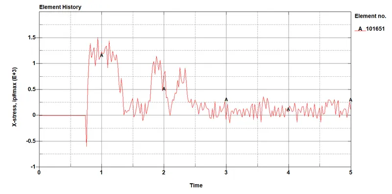
Elemental X-stress for both beam and solid spotweld elements
Elemental strains in x- axis for both beam and solid spotweld elements
Conclusion:
The spotweld modelling using solid and beam elements yield similar results in terms of energies, stress and strain plots.
Similar procedures have been followed as in case of simulation in challenege 4