Week 6
AIM:
To make Appropriate Connections of car rear door at required places.
OBJECTIVE:
Deploying the connections between the different components in the given model by, Using 1D or 2D connectors i.e seam, spot, bolt, masses, C-BUSH etc. Make sure all the connectors get realised.
CONNECTORS:
Connectors are geometric entities, Which are primarly used to represent the cad geometric connection in terms of FEA. Connections can be created as a spot-weld, seam-weld,bolt,C-BUSH,masses etc. A realized connector will be consider as the successful representationof a CAD mode.
FEA MODEL:
*It is make sure that without having FEA we can not create any connectors.
*Given Rear door FEA model is show in below figure.
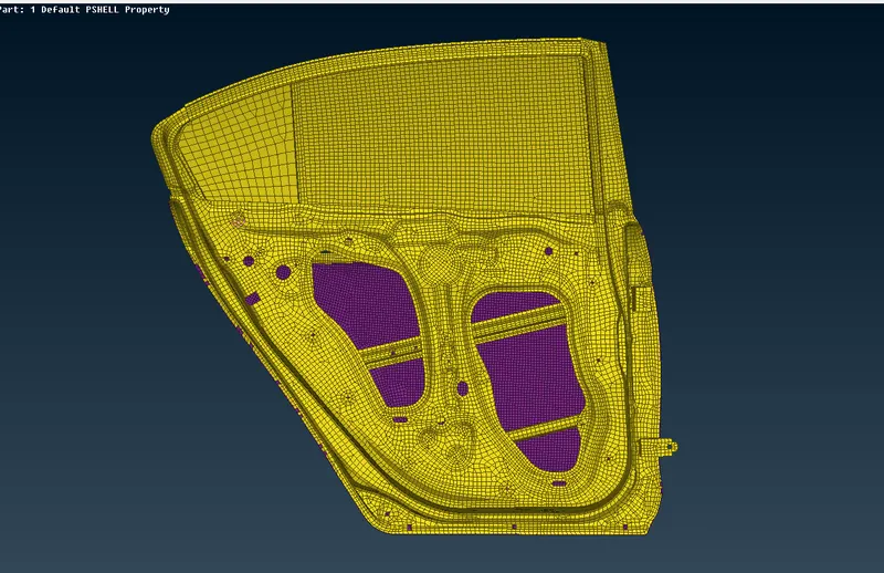
Fig(1).
PROCEDURE:
1.Import the given rear door.nas file by, Selecting the FILE >> INPUT >> NASTRAN.
2.In this model there are different types of connections are made to different components using sutable connectors. Before giving the connections observe the FEA body carefully and think which is best for prticular components.
3.The connections made in the model is listed below :
i.Bolt .
ii.Cluster.
iii.Rigid.
iv.spot.
v.mass.
vi.C-Bush or spring.
i.BOLT CONNECTION:
*Generally bolt is used to combine the two or more components to restrict the movement of the components.
*There are two methods to create the bolt connections in ANSA :
METHOD 1:
- First select the bolt connection hole with two or more layers then create the 3D point by selecting the TOPO >> POINTS >>ON COG>> EDGES.
- After that convert the 3D point into bolt using convert option.
- Using Connection Manager option select the bolt 3D point and click middle mouse button .
- Here we have to select the p1 and p2 i.e ( part 1 and part2 )then select the connection type is BOLT then given search tolerence is 10.
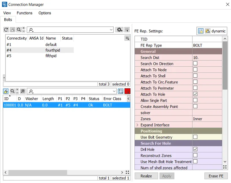
Fig(2).
- After providing proper values shown in below Fig(2) then Apply and realize the BOLT connection.
- The status is 'oK' then it i successfully realized the connefction.
- The FEA represent of bolt connection is shown in below Fig(3).
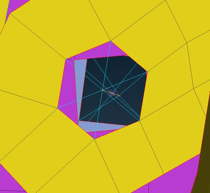
Fig(3).
METHOD 2:
- This connection made by using NAS Module.
- Select the two layer hole and make rigid connections by, Selecting the NAS >> ELEMENTS >> RBE2.
- select the slave nodes of hole and click middile mouse button ANSA automatically create the master node and connect all slave nodes to master node through RBE2 elements.
- Similarly do the same process for the secound hole and create RBE2 elements.
- Now connect the both master nodes with Two node RBE2 element.
- FEA representation of bolt is shown in Fig(4).
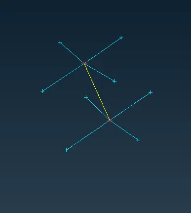
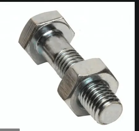
FEA of bolt Fig(4). Bolt and Nut Fig(5).
- By Comparing both FEA representation of bolt and practical bolt we can observe that head of the bolt ,Nut and stem.
ii.CLUSTER:
* Cluster is a rigid connection between two components but it has only one master node for both hole slave nodes.
*Select the two layer hole and make rigid connections by, Selecting the NAS >> ELEMENTS >> RBE2.
*select all the slave nodes in both the holes and then given one master node all the RBE2 elements get connected to that master node and form Cluster connection.

Cluster Connection Fig(6).
iii.RIGID CONNECTION:
*It is a simple connection that can make in hole by, Selecting the NAS >> ELEMENTS >> RBE2.
*Select all the slave nodes and then click middle button to create master node and make all Rigid connections as shown below Fig(7).
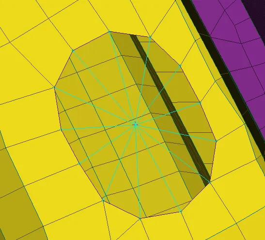
RIGID CONNECTION Fig(7).
iv.Spot weld :
*Spot welding is a resistance welding process that is used primarily for welding the two or more metal sheets together by applying pressure and heat at the weld area. Heat for the welding process will be obtained from the resistance to electric current.
*To make spot weld connection first create 3D spot weld point by, selecting the TOPO >> POINTS >>ON COG>> EDGES.
*After that convert the 3D point into spot weld using convert option.
*Using Connection Manager option select the spot weld 3D point and click middle mouse button .
*Here we have to select the p1 and p2 i.e ( part 1 and part2 ) then select the connection type is RBE3-HEXA-RBE3 then given search tolerence is 10.
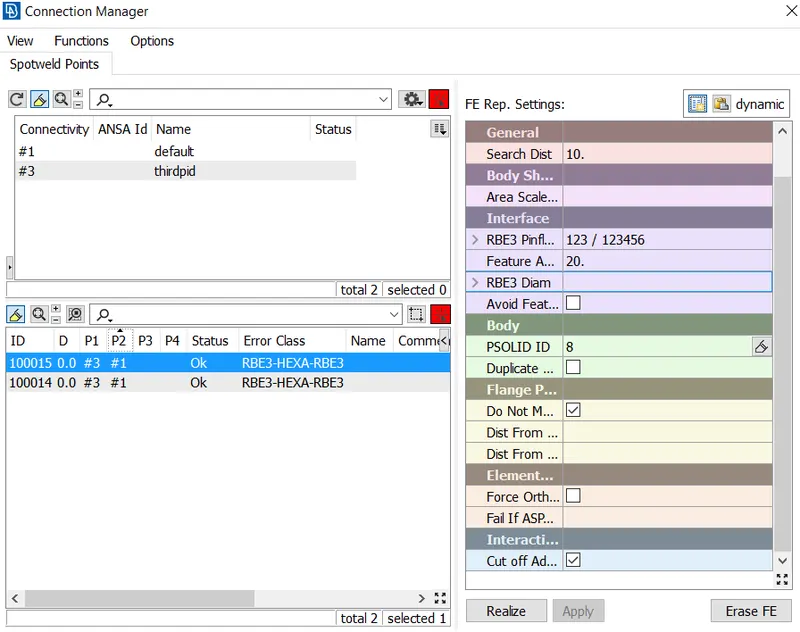
Fig(8).
*In this connection manager assign PSOLID property for spot weld connection then click on apply and realize.
*The status is 'oK' then it i successfully realized the connefction.
*The FEA represent of spot weld connection is shown in below Fig(9).
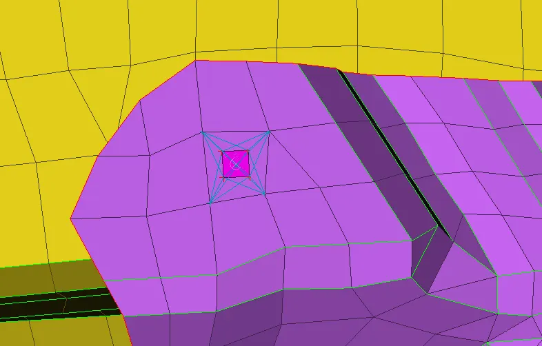
Spot Weld Connection Fig(10).
v.Mass:
*In rear door model handle of the door is represented by, RBE2 elements and mass of the handle is applied at the centre of the handle as shown below figure.
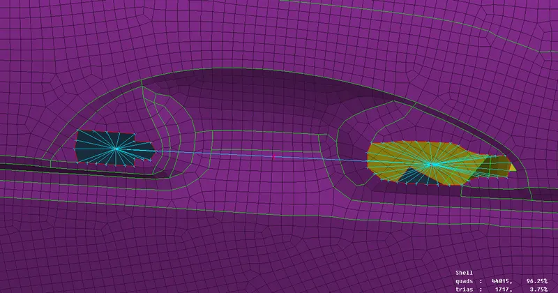
HANDLE OF THE DOOR Fig(11).
*To create above connection in ANSA, first make to rigid connections at both the wholes and connect those two master nodes with RBE2 many one option.
*Hence again we can get one more master between two holes there we supose to apply the mass of the handle.
*In ANSA always apply the mass in the units of tones by, Selecting the NAS >> ELEMENTS >> CONMi >> CONM2.
*Mass i applied at centre of the handle is 100 grams in property card of the mass is shown in figure below.
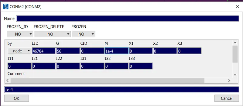
Fig(12).
vi.C-BUSH:
*The C-BUSH is generally a spring element which i having damping co-efficents in three directions.
*C-elastic elements are mono-directional if we want to create a stifness in all three direction we need to create three c- elastic element, therefore C-BUSH is the best alternative for C-elastic elements.
*To make C-BUSH connection first generate the curve along the feature.
*After that convert that curve into spot line using convert option.
*Using Connection Manager option select the spot line and click middle mouse button .
*Here we have to select the p1 and p2 i.e ( part 1 and part2 ) then select the connection type is RBE3-HEXA-RBE3 then given search tolerence is 50.
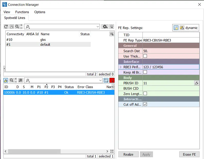
Fig(13).
*Create PBUSH ID to collect all the connections.
*After creating C-BUSH connections align all C-BUSH local co-ordinates to global co-ordinates by, Selecting all the C-BUSH elements >> modify.
*In modify option we can change orientation ,CID ( co-ordinte ID), give all C-BUSH elements CID is zero to represent the global co-ordinate.
*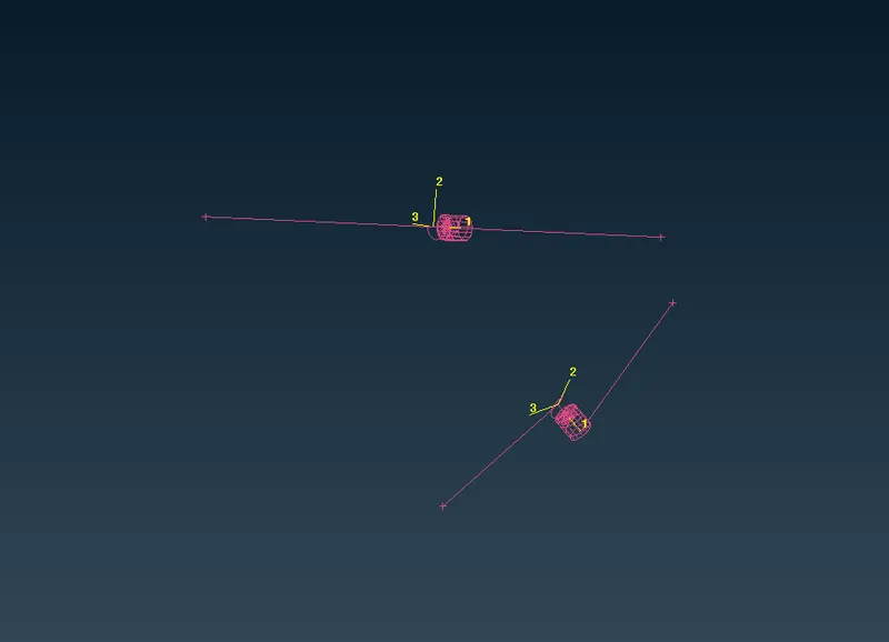
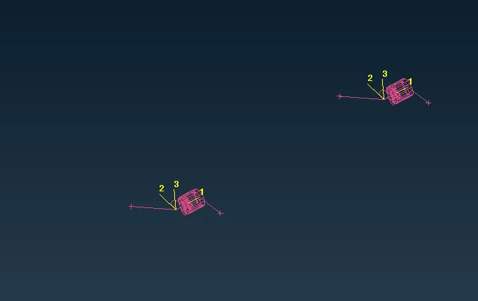
Before changing the CID Fig(14). After changing the CID Fig(15).
NEW THING LEARNT IN THIS CHALLENGE:
*Understand how to create
1.Appropriate connections of Rigid elements.
2.Spot weld connections.
3.C-BUSH Connections.
4.Mass, seam weld etc.
RESULT:
*All above mentioned procedures is used to make connections between the components present in given rare door model using different connectors as shown in Fig (16).
*Connectors are geometric entities, Which are primarly used to represent the cad geometric connection in terms of FEA.
*The final image of the all the connections of rear door is shown in below figure.
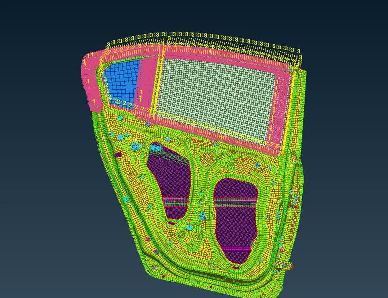
All connections of rear door model of car Fig(16).