Pre-processing of dashboard or instrument panel of car using ANSA
Pre-processing of dashboard or instrument panel of car using ANSA
Aim :- To pre-processing of given instrument panel of car within quality parameters.
Objectives:-
- Introduction to shell meshing or 2 D meshing.
- Topological errors and geometry errors clean-up.
- Extracting mid surface with different method.
- Meshing the geometry within quality parameters.
- Rectifying quality errors i.e. solving off elements.
- Improving mesh flow pattern.
Given quality criteria:-
|
Sr.No, |
Quality criteria |
Value |
|
1 |
Target /Average element length |
4 |
|
2 |
Minimum length |
2 |
|
3 |
Maximum length |
6 |
|
4 |
Aspect |
3 |
|
5 |
Warpage |
15 |
|
6 |
Skewness |
45 |
|
7 |
Jacobian |
0.7 |
|
8 |
Minimum quad angle |
45 |
|
9 |
Maximum quad angle |
135 |
|
10 |
Minimum tria angle |
30 |
|
11 |
Maximum tria angle |
120 |
|
12 |
Tria percentage |
15 |
Software used :- Beta CAE ANSA V19.1.6
Abstract :-
In this project, preprocessing stage in CAE is done on given CAD model of instrument panel of car dashboard in a beta cae ANSA v19.1.6 software.here I illustrate the geometry clean up, mid surface extraction and 2 D meshing over instrument panel also good practices to be followed during 2 D meshing is described in this project.
Methodology :-
- Importing geometry into ANSA
- Topology and geometry cleanup
- Extracting mid-surface
- Assignning quality and meshing parameters
- Meshing part by part, improving mesh pattern and eliminating off elements
Introduction :-
Instrument panel is a control panel for driver of vehicle which is situated ahead of drivers seat. Instrument panel includes speedometer, fuel gauge,airbags, steering columns, media control panel, glove box bean, air ducts, side indicators, seatbelt warning, GPS navigator, mobile holder,etc
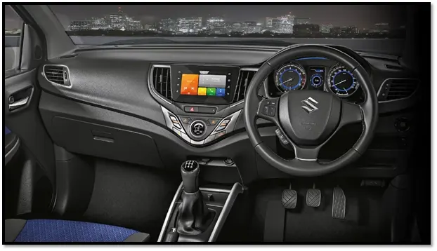
Fig a. : Instrumentation panel
As shown in below image instrumentation panel is situated on Crossed car beam fixed at both ends. Most of the instrument panel is made up of PP-EPDM-T20 material but also some other materials used in this instrument panel assembly. Four air outlet, glove box handle, media control panel as well as instrument cover are made by PC/ABS(polycarbonate/ acrylonitrile butadiene styrene). AC duct are made by HDPE(High density polyethylene). In NVH analysis various ribs are introduced on inner surface of instrument panel for incresing stifness of instrument panel.
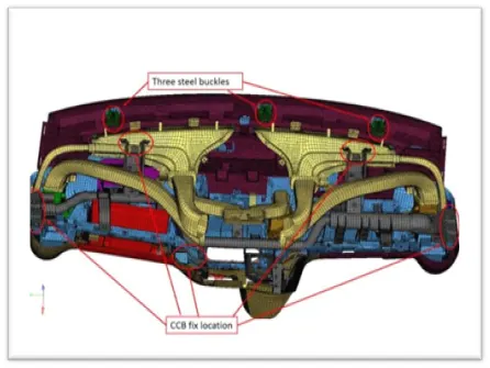
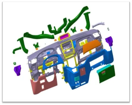
Fig b : Instrumentation panel assembly
Procedure :-
1.Import CAD model into ANSA.
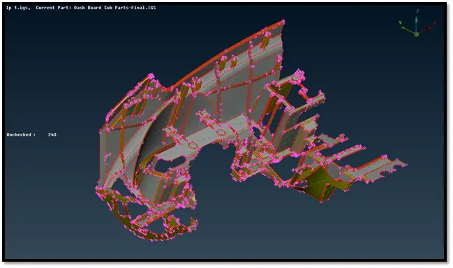
Fig 1.1 Imported model into ANSA
- Topology and geometry cleanup :-
After importing model into ANSA we can see there are many errors in CAD model while doing geometry check as shown in below image. Enabling all the errors while doing geometry cleanup except unmeshed micros and sharp edges and click on excute button, you will see many errors. We can rectify these errors by manually one by one or we can clear all these errors by auto fix method by just right clicking on all selected errors and click on fix option it clears all errors in one shot automatically but still some errors need to be clear manually one by one with deleting unnecessary areas formed due to hot points, deleting unnecessary hot points, creating new area, realeasing coons and Topo option.
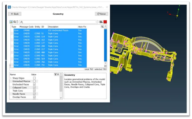
Fig. 2.1 Geometric errors obtained during geometry cleanup
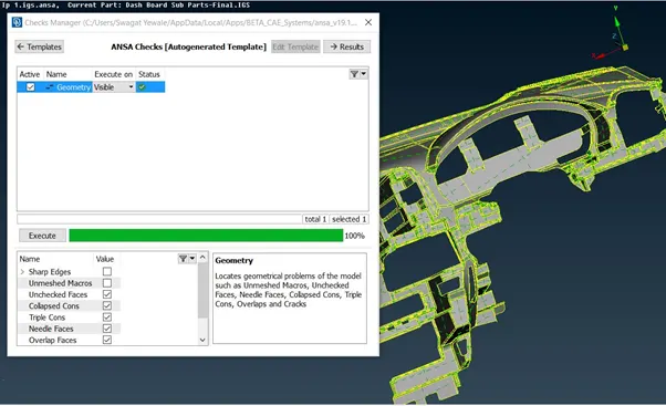
Fig. 2.1 Geometric errors rectified during geometry cleanup
Next, we have to measure the thickness of all parts of instrument panel for extracting mid-surface by offset method. Different thickness parts needs to be assigned seperately.
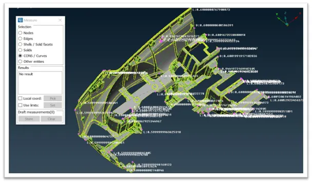
Fig. 2.2 Measurement of model
Next we have to check orientation. Orientation should check throughout by user till last stage of preprocessing all parts should be having correct orientation because orientation issue will occure at final step when usre merge model with complete assembly of model. It is always preferred to maintain the continuity over surface either grey or yellow color throughtout the faces.
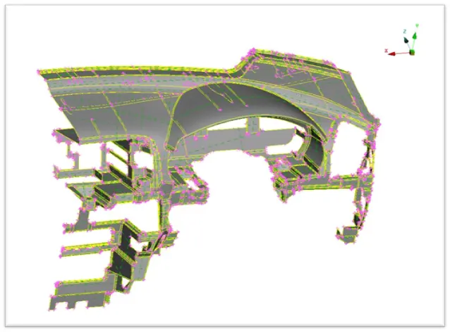
Fig. 2.3 Orientation
3.Extracting mid-surface :-
Mid surface can be extracted by two methods 1) Manual method and 2) Auto mid surface method.
1] Manual method : In manual method we use Topo > Faces > offset option for extracting mid. Manual method is time consuming but extracted mid is accurate as compared to auto mid method, therefore I go for manual method for extracting mid-surface. For surface containing complicated features first select the less surface feature and offset it at mid as shown in below image 3.1 After creating mid surface assign PID and thickness to it. In manual method ANSA always ask to delet parent geometry or not,while in auto mid surface method parent geometry is deleted without asking to user.
2] Auto mid surface generation : For auto mid surface generation in TOPO module Mid.surface > Skin and Mid.surface > Casting option available in ANSA. This is very quick method of extration of mid but in complicated geometry it does not give proper results. If geometry of model is simple we can go for this method.
- Generation of mid surface for upper cover of instrument panel :
Here, thickness of 0.6 mm is uniform across upper cover of instrument panel so I used TOPO > Offset option and select value 0.6/2 mm for getting mid surface at midle. while selecting area I select feature option so that whole area is captured in one shot. While selecting area for offset option always select the area which are having less features.
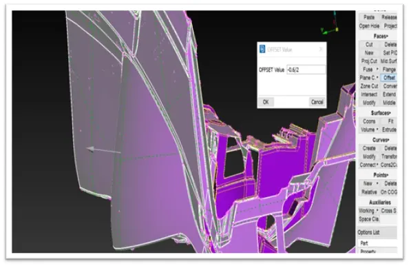
Fig 3.1 Mid surface extraction by offset method
- Generation of mid surface for ribs :
For generating mid surface for small ribs I used Topo > faces > Midle > Single option after that select both sides of ribs which surfaces need to mid surface after midle click ANSA generate mid surface.
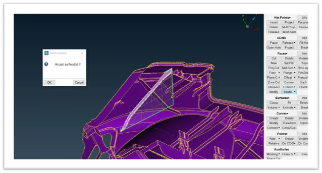
Fig 3.2.1 Mid surface generation for ribs
- Mid surface generation for dog houses
For genrating mid surface of dog houses I used offset method we can also generate mid by cons2curve option but it cannot captured geometry properly so I go for offset method. Here thickness of dog houses is varies between 0.8 mm to 1.2 mm so I select offset value is 0.5 mm from surface. This method becomes time consuming and complicated while extending mid to base surface and meshing so I will not suggest this method for extracting mid for dog houses. After obtaining mid of dog houses assign PID and thickness to dog house.
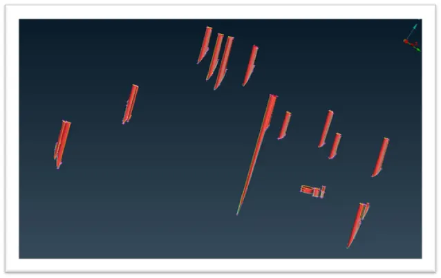
Fig 3.3 Mid for dog house
- Mid for bracket :
For extracting mid of bracket use TOPO > faces > midle > option, thickness of bracket is varies so assign PID for each surface of bracket having different thickness and also assign related thickness to it.
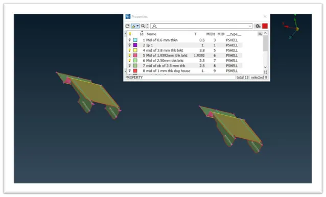
Fig 3.4 Assigning PID and thickness to each part of bracket
After extracting mid of each parts make extension or connection to the base geometry by TOPO > Faces > Extend option and store view of mid surface by lock option for meshing purpose.
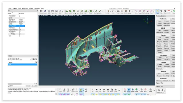
Fig.3.5 Mid surface view
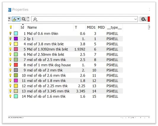
Fig. 3.6 Assign PID to each parts
- Assignning quality and meshing parameters
In this project meshing parameters and quality parameters are given in problem statement assign this parameters by Mesh parameters and quality criteria option utilities section for this project mesh parameters and quality criteria are shown in figure below.
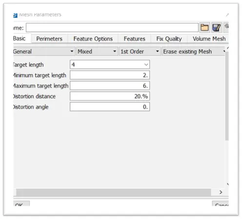
Fig. 4.1 Mesh Parameters
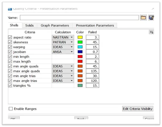
Fig. 4.2 Quality parameters
Quality parameters :-
- Warp angle :- It is angle between normal of two planes of quad element by spliting it diagonally. The ideal value of wrap angle is 0 degree but it is allowable till 15 degree.
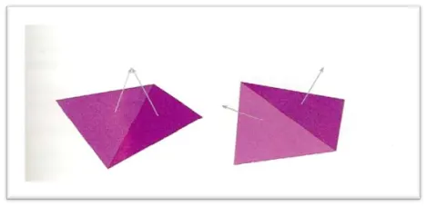
Fig. 4.3 Warp angle
- Aspect ratio : It is defined as maximum edge length of element to the minimum edge length of element. Ideal value is 1 but it is acceptable till 5
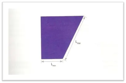
Fig 4.4 Aspect ratio
- Skewness : Skew for quad element = 90 ° – minimum angle between two lines joining opposite mid mid sides of element. (α )
Skew for tria element = 90° - minimum angle between two lines from each node to opposing mid-side and between two adjucent mid-side at each node of elements. Ideal value is 0° and acceptable till 45°
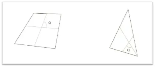
Fig. 4.5 Skewness
- Jacobian :- It is scale factor which arises due to transformation of co-ordinate system. Ideal value is 1 but it is acceptable greater than 0.6
- Meshing part by part, improving mesh pattern and eliminating off elements
For meshing we can go by three algorithms i.e. Best, Spot mesh and free mesh. Here we will go with best mesh algorithm. Although we used best mesh algorithm but reconstruction and smooth option is necessary after mesh generation. Generate part by part mesh with Mesh > Shell Mesh > Best > Select option after that always use reconstruction and smooth option for better mesh flow pattern
For better mesh flow pattern following practices need to followed :
- Tria should not face to each other as shown in below image also back to back tria element should be avoided.
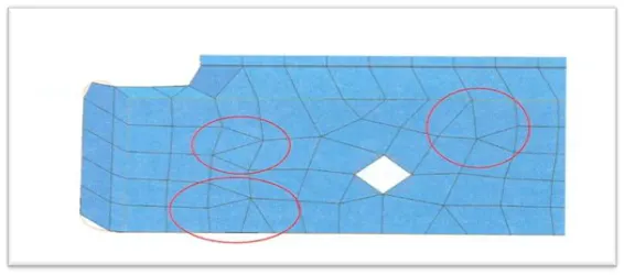
Fig. 5.1 Back to back tria should be avoided
2.On a plane surface tria should be avoided
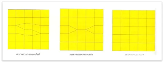
Fig. 5.2 On plane surface tria should avoided
- Avoid tria at outer perimeter and near to holes.
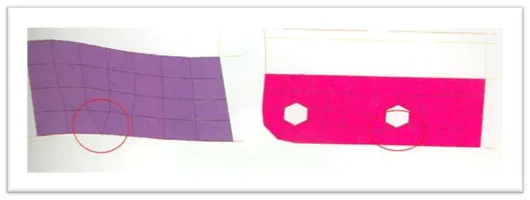
Fig.5.3 Tria should not present on perimeter and holes
- Nodes should lie on surface no kinks,raise or deep present in model.
5.Avoid zig-zag mesh flow pattern
6.No rotating mesh flow patteren present near holes.
7.Holes should be even number of nodes and its edge should be parallel to nearest parameter.
- Divide the surface in smaller parts by cut option and after meshing remove it by join option for better mesh flow pattern.
- Defeature the area where quality parameters fails.
Difficult to capture feature and off elements :
Following are images of where off elements are generated and unable to clear it due to geometry complexity.
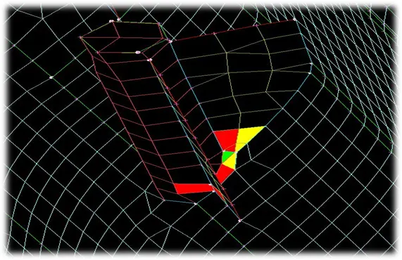
Fig. 5.4 Elements failing on rib due to aspect ratio and minimum length
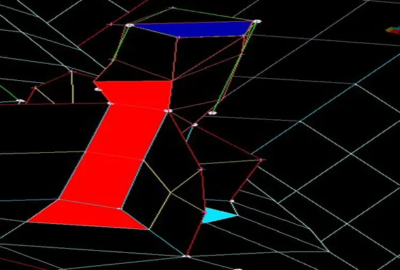
Fig. 5.5 Elements failing due to min length criteria on rib having edge length less than min length criteria
Rectifying Kinks and raised edge in the model :
For eliminating kinks and raised edges of element we can use Mesh > Grid > Align option as shown in below images. First select source i.e. raised edges node then select any three points on surface where node should be present after that on midle click confirmation raised kink is on placed surface in this similar manner we can remove any dips or dents element on surface.
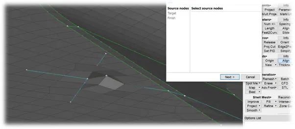
Fig.5.6 Select align option and source node
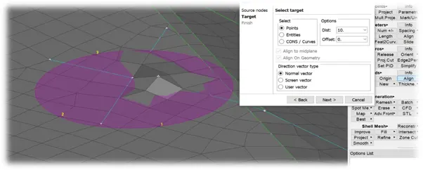
Fig. 5.7 Select any 3 points on surface where source node should present
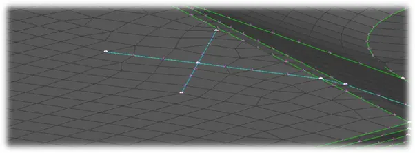
Fig 5.8 Kinks eliminated
Results after meshing :-
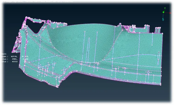
Fig. 5.9 Front view of instrument panel
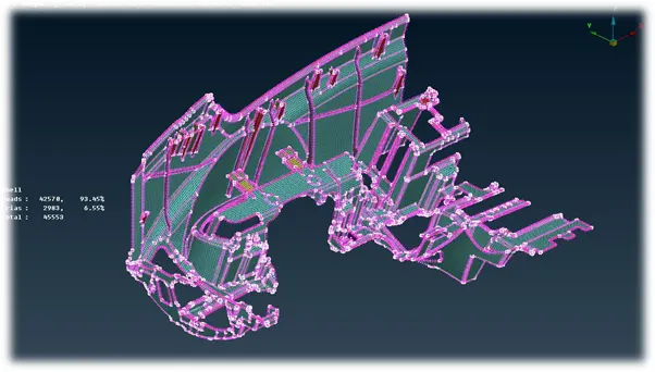
Fig. 5.10 Isometric view of instrument panel
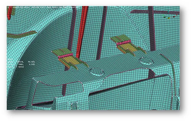
Fig. 5.11 Results after meshing and enabling shell as solid
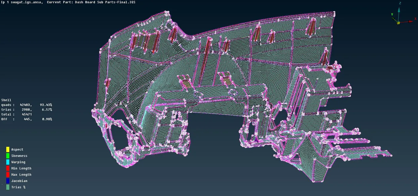
Fig. 5.12 Hidden mode of model
Learning Outcomes :-
- Learned 2 D meshing ( Shell meshing)
- Importance of quad and tria elements.
- Learned quality parameters in meshing
- Able to eliminate geometrical errors.
- Able to obtained mid surface for critical geometrical parts.
- Able to understand best practices should be followed during meshing foe better mesh flow patterens.
Conclusion :-
The instrument panel had been meshed using shell meshed. The total 45471 elements are generated in which 42485 are quad elements and 2988 are tria elements generated, Also 445 off elements are generted due to geometry constraint. Able to achieve best mesh flow pattern by using reconstruction,smooth,swap,split,align,paste,etc options. Thus,the instument panel is complitely preprocessed and ready for further solver and postprocessing.