Week 6-3D Tetra Meshing Challenge
Aim: Aim of this challenge is to create 3D tetra mesh on the provided geometries using different types of 3D meshing methods available in hypermesh
Procedure:- To start working with the model, first we'll import the model 1 into hypermesh working enviornment.
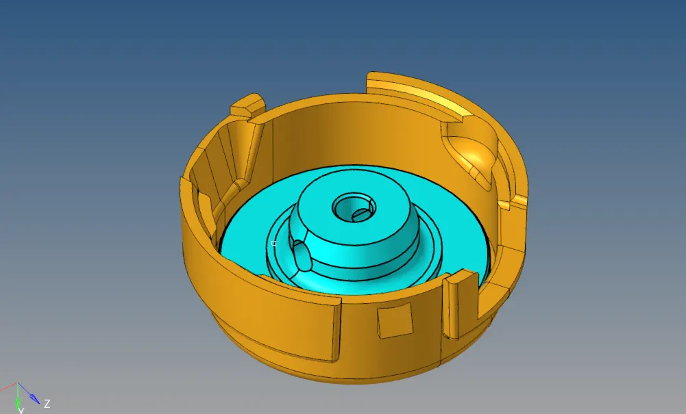
Figure 1: Showing the model 1 in hypermesh working environment
After opening the model, we will visually inspect the model for any errors in geometry, and if there are any then we'll fix them.
In this model, we have to create tetramesh for the model by converting 2D mesh to 3D mesh. So, first we will create 2D mesh on over the geometry, by using 2D mesh options. We will first feed the quality criteria into the criteria file setting.
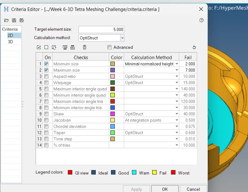
Figure 2: Showing the various meshing criteria options available
After feeding the meshing criteria, we will use auto-mesh option to create the mesh over the surfaces. If there are any solid bodies, then we'll delete them and after deleting them we'll left with only surfaces of the solid bodies. We will use these surfaces for the meshing.
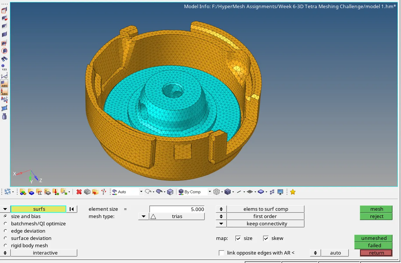
Figure 3: Showing the created 2D mesh over the surfaces of bodies.
Now, to convert the created 2D mesh to 3D mesh, we'll use the 3D mesh option. In 3D we use tetramesh and then tetra mesh option.
here, we select the created 2d tria mesh elements, and it will fill them with 3D elements.
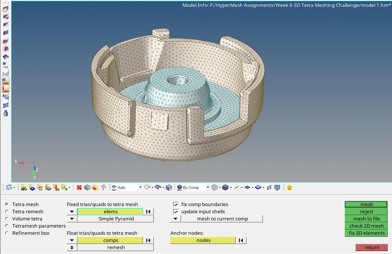
Figure 4: Showing tetra mesh option and selected 2D elements
After creating the 3D mesh elements, we have to delete the previously created 2D mesh elements. This can be done by selecting the elements by config and then selecting tria3 elements.
Now, 3D mesh is created and to check the quality of 3D mesh using tet collapse criteria we use check element and use tet collapse option.
If required we'll fix the elements which are falling in tet collapse criteria. This can be done by increasing the length of the edge of the element.
After fixing the quality, the meshing of model 1 is completed.
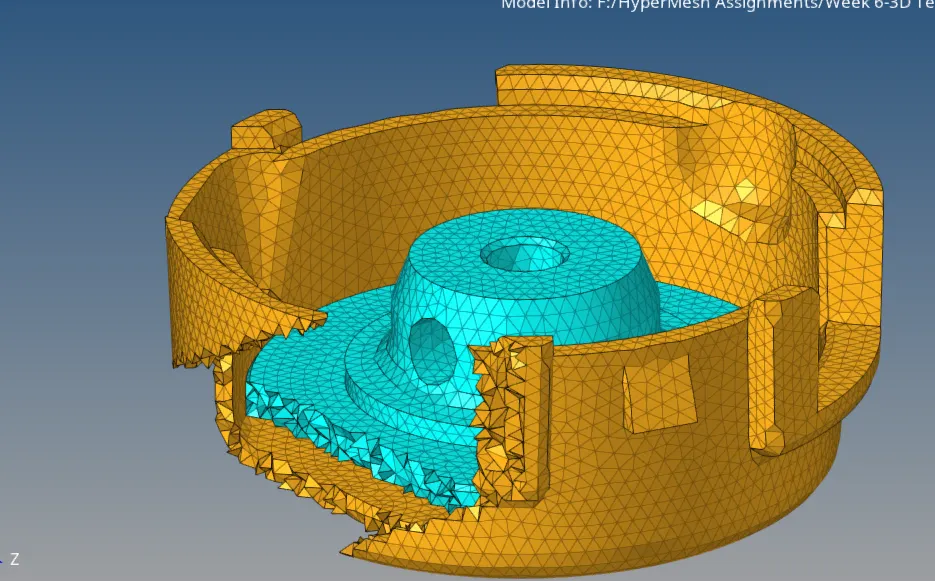
Figure 5: Showing 3D tetra mesh with section view of model
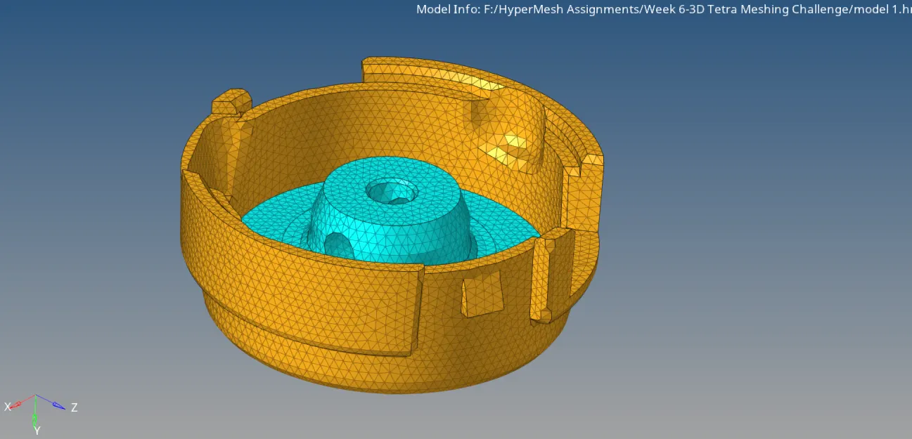
Figure 6: Showing complete mesh of model 1
Now, we'll import the model 2 into the hypermesh work window.
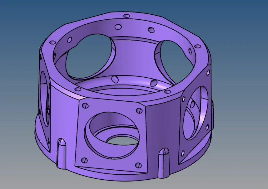
Figure 7: Showing imported model_2 into hypermesh window.
Now, to create the 3D tetra mesh of model, we use 3D mesh option, and then use volume tetra mesh option. Then we select the surface of the model. For this to works, the model must be a closed model. If model is closed, whole model can be selected by selecting the one face.
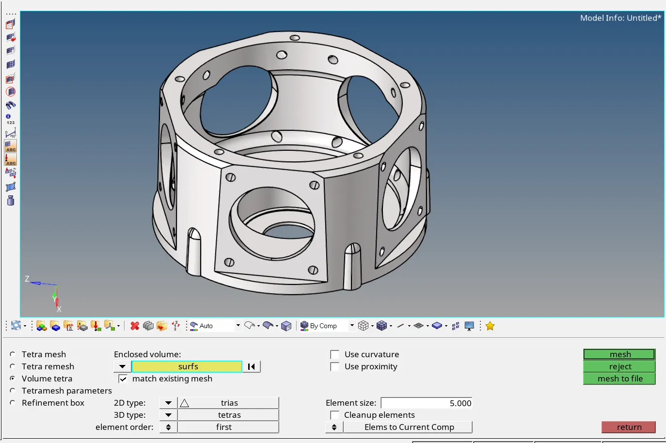
Figure 8: Image showing Volume tetra mesh option
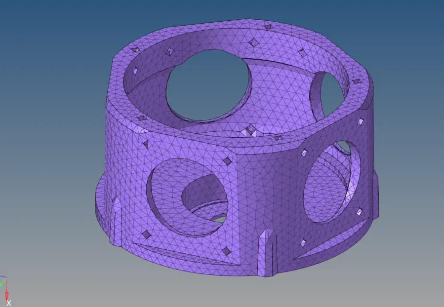
Figure 9: Image showing created volume tetra mesh of model 2
Now, to check the quality of mesh on tet collapse criteria and fix them, we use the same method we used earlier in model 1. After fixing the elements and passing all quality criteria, our model 2 is ready for further processing.
Now, we'll import the model 3 into the hypermesh working enviornment.
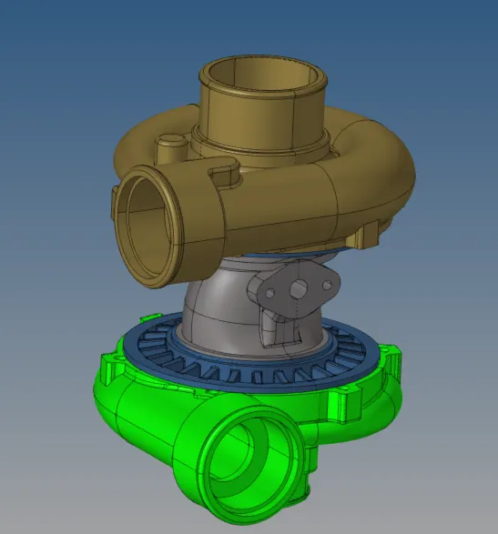
Figure 10: Image showing the imported model 3
To mesh the given model 3, we will use quick tetra mesh option. To use the quick tetra mesh option, we go to utility option and then select quick tetra mesh.
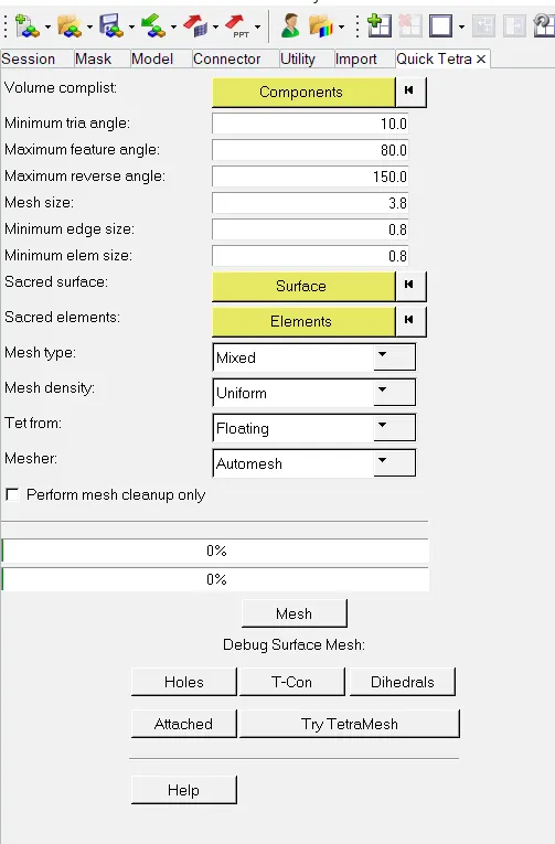
Figure 11: Showing quick tetra mesh options
Here we select the components, which we want to mesh. And then gives the various input parameters like target element length, minimum element length, maximum element length and type of elements we want in the model etc. After hitting the mesh button, we will get the quick tetra mesh on the components, according to our given parameters.
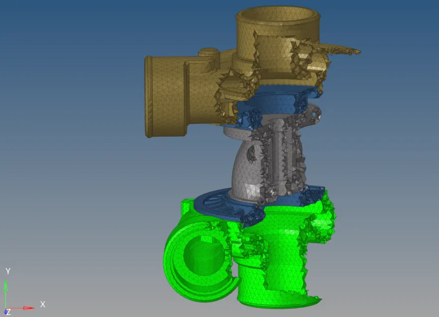
Figure 12: Image showing elements created using quick tetra mesh (used masked to show inside elements)
After that, if required, we will fix the 3D elements quality, in the same way as we have done in case of model 1. After that our model will be ready for further processing.
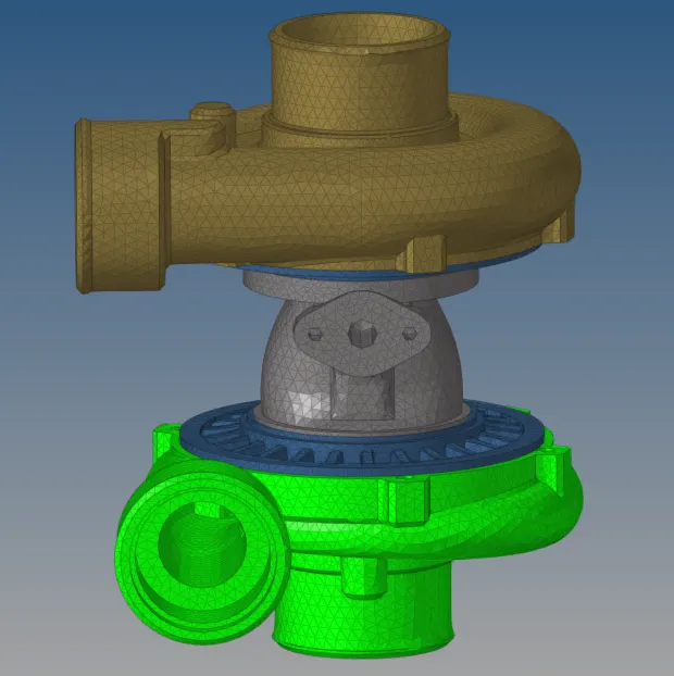
Figure 13: Image showing final mesh on components of model 3.