Meshing and Connections on a Suspension Assembly using ANSA.
Report on Meshing of a Rear Suspension Assembly of an Automobile
- Aim: To Mesh the various geometries given in the Suspension Assembly and make the appropriate connections.
- Procedure: 1. The very first step in Meshing the Geometry is the step of Geometric Clean up. To perform this operation I used the Geometry option under the Checks Manager. After Selecting this command, I gave put in the necessary parameters for checking and ran the command.
As we can see, there are a lot of errors in the Geometry,
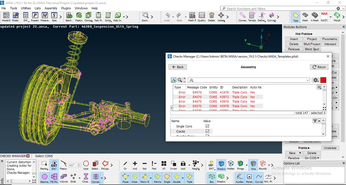
Before Geometric Clean up.
All these errors were resolved to get a Geometrically clean model.
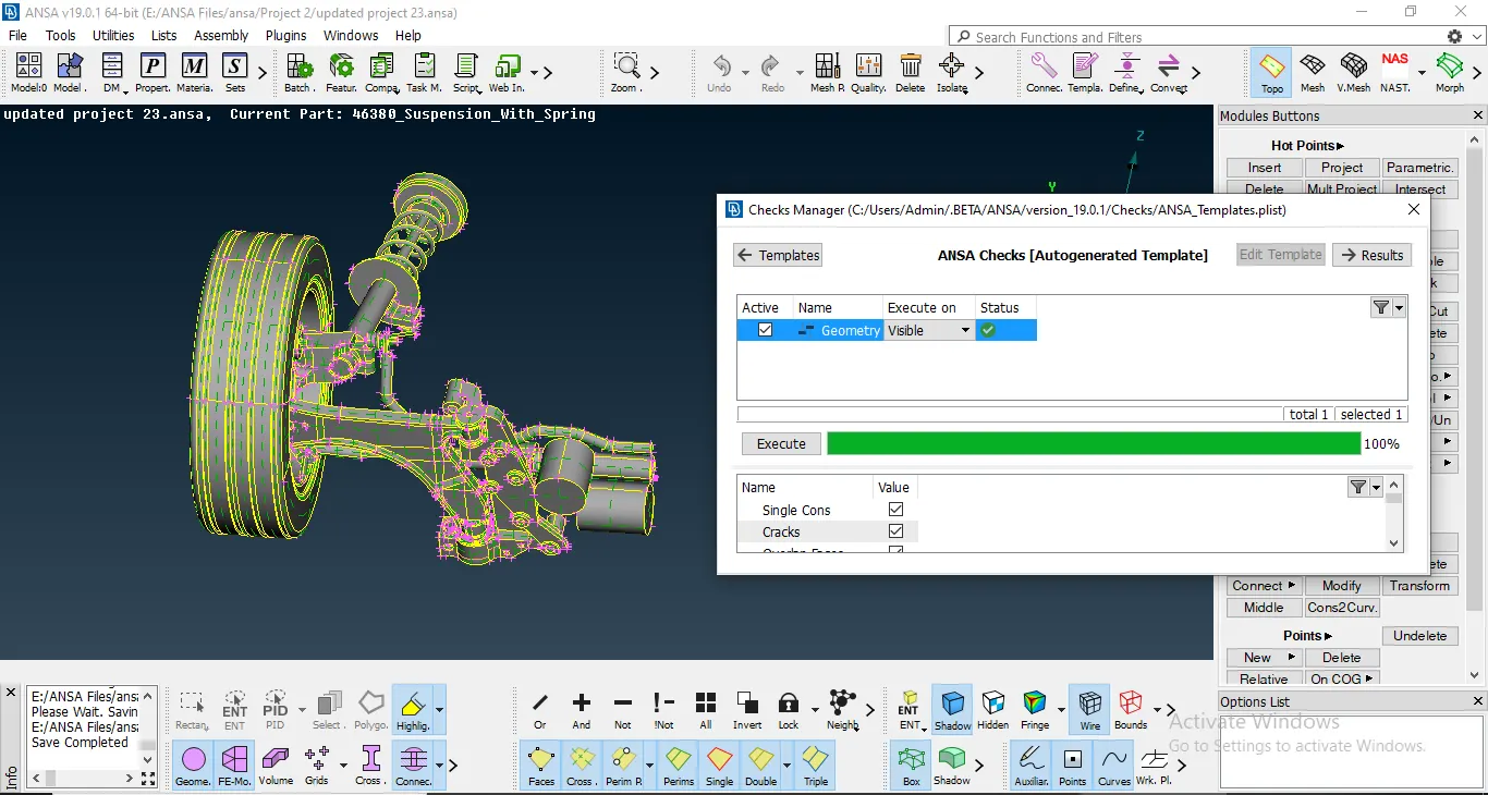
After Geometric Clean up.
2. Now since the Geometry is already divided into three different PID's, I meshed the tyre component. Now, since the thickness of the component is greater than 5mm, the volume Mesh is to be deployed. I used the tria and ortho tria mesh on the surface of the component.
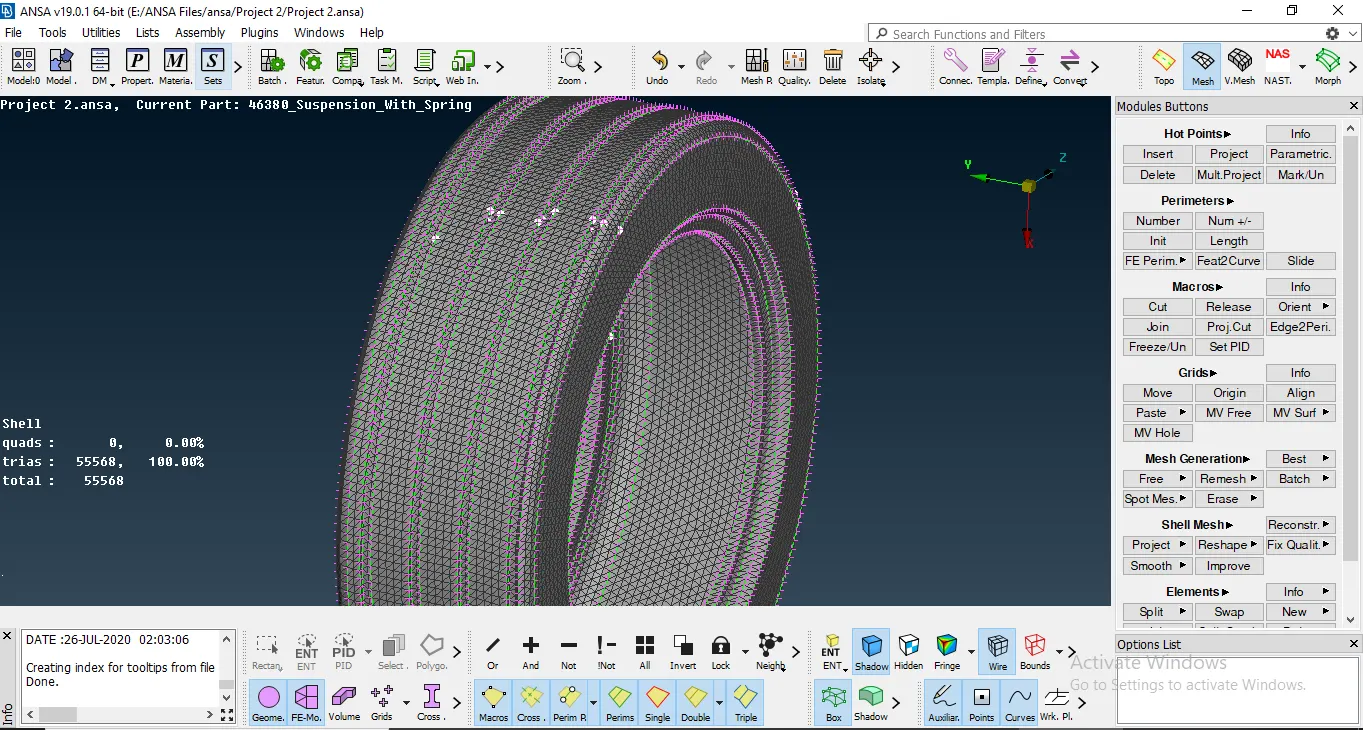
Tyre Surface Mesh.
After Meshing on the surface, I removed the errors on the surface and then created a Volume from the given Geometry. For this, I used the Volume Mesh Tab and defined a volume using the Define option under the Volumes tab. I then defined the Volume as the Geometry shows. Then I used the Tetra FEM Meshing technique to mesh the volume and checked for the Tet Collapse error on the Volume Mesh.
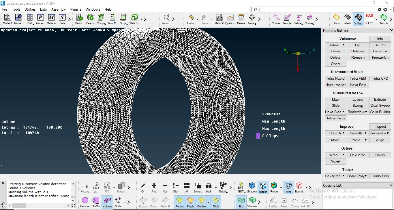
No Tet Collapse Error on the Volume Mesh.
3. Similarly, I meshed the other components volume by volume. To do that, I used the PID Region option and then Meshed the component according to their thickness. Where the thickness of the component was either non uniform or greater than 5mm, then the Volume Mesh was deployed on that particular component. If the thickness was less than 5mm, then the Mid-surface was taken and then a mixed type of meshwas deployed on the component.
The next component to be meshed is the Rim. Similar to the procedure for the tyre, I meshed the surface of the rim with Tria and Ortho Tria mesh elements. I then later removed and resolved all the off elements. After meshing the surface, I defined a volume to the geometry and meshed the geometry using the Tetra FEM technique. And i checked the volume mesh for the presence of any Tet collapse error.
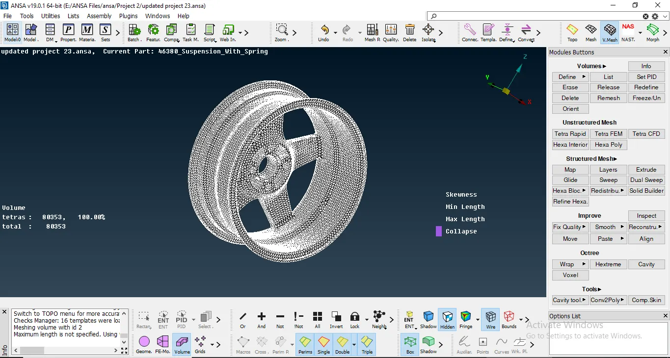
No tet collapse for Rim.
4. Later I went onto the suspension assembly, where i segregated the different volumes using the PID region option.
If the thickness was less than 5mm, then the mid surface was taken, else the surface meshing was done using th tria and ortho tria elements. Some of the components are shown below:
4a. Knuckle: Since the thickness was more than 5mm, surface meshing was performed and the volume was defined. The volume was meshed with Tetra FEM technique. the presence of any Tet collapse error was resolved later in the volume mesh.
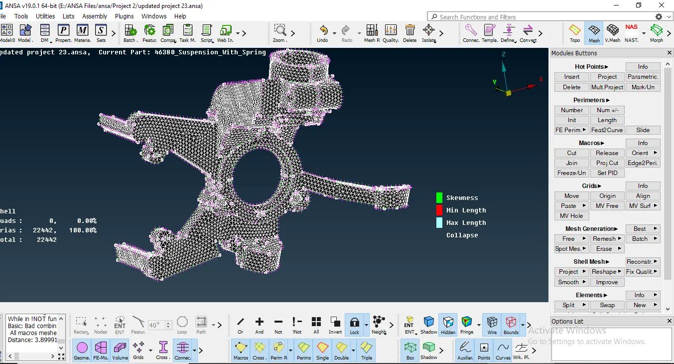
No off elements on the component.
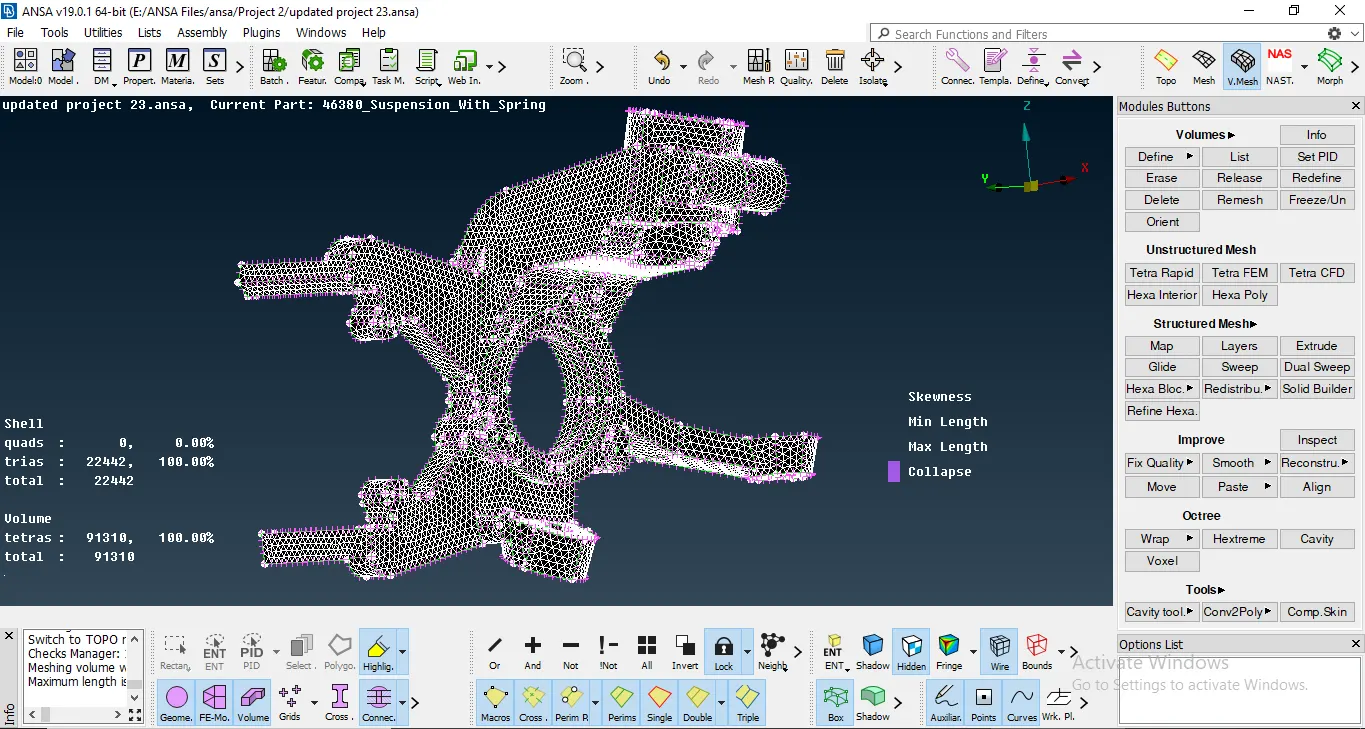
No Tet Collapse.
4b. Brake Caliper: Another Component in the Suspension Assembly is the Brake Caliper and since the thickness was more 5mm the tria and ortho tria element mesh was deployed. Then I defined the Volume and did the Tetra Mesh type on it. I then resolved all the Tet collapse off elements on the component.
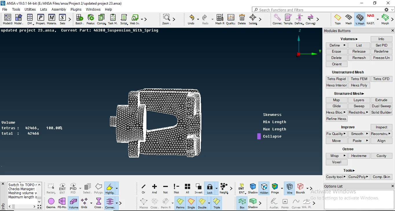
No tet Collapse on the Volume.
5. I then went to meshing the entire assembly volume to volume after checking the thickness of the volume and then deciding the type of mesh to be used. Some certain parts had thickness less than 5mm and the others have more than 5mm.
A certain parts of the Geometry had thickness less than 5mm. The mid-surface was taken by the Offset command. Since the thickness was uniform for a particular component, the Offset command with the Feature option takes the mid-plane for the component at one go. Then meshing the component is done with the Mixed Elements that consists of Quads and Tria Elements. The number of tria elements can also be reduced by various commands like Reconstruct, split etc. All the Off elements are also resolved after the meshing is done.
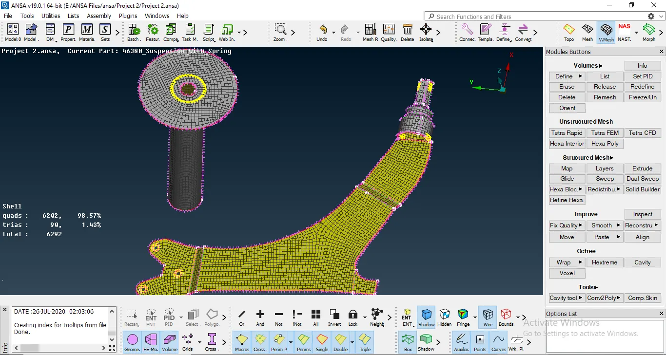
Meshing on the mid-surface.
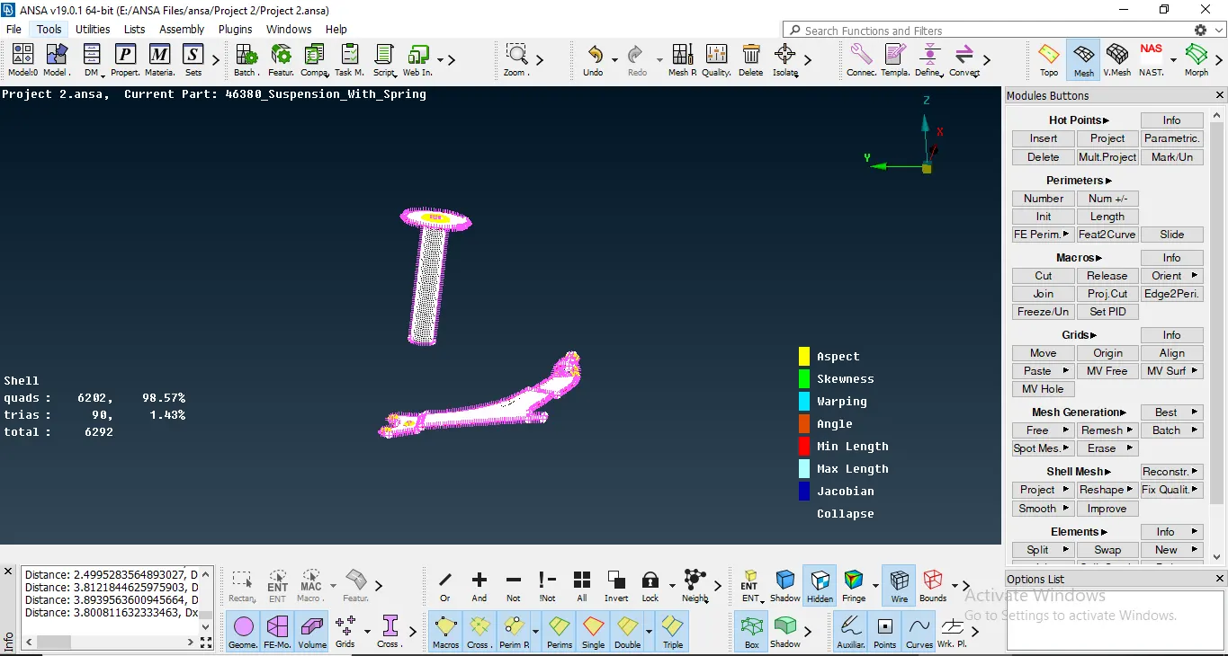
No off elements on the mid-surface.
6. All the various components in the assembly are meshed accordingly and the off elements are resolved as well. For the Volume Mesh, there are no Tet Element errors as well.
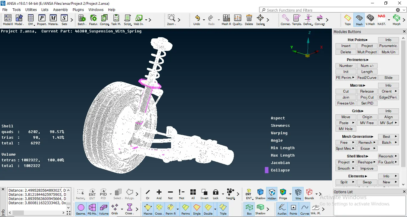
No Tet collapse for entire model.
7. Connections: After the meshing for the assembly is done, I gave the required appropriate connections. I noticed all the possible areas where there is a connection possible and have made an RBE2 connection.
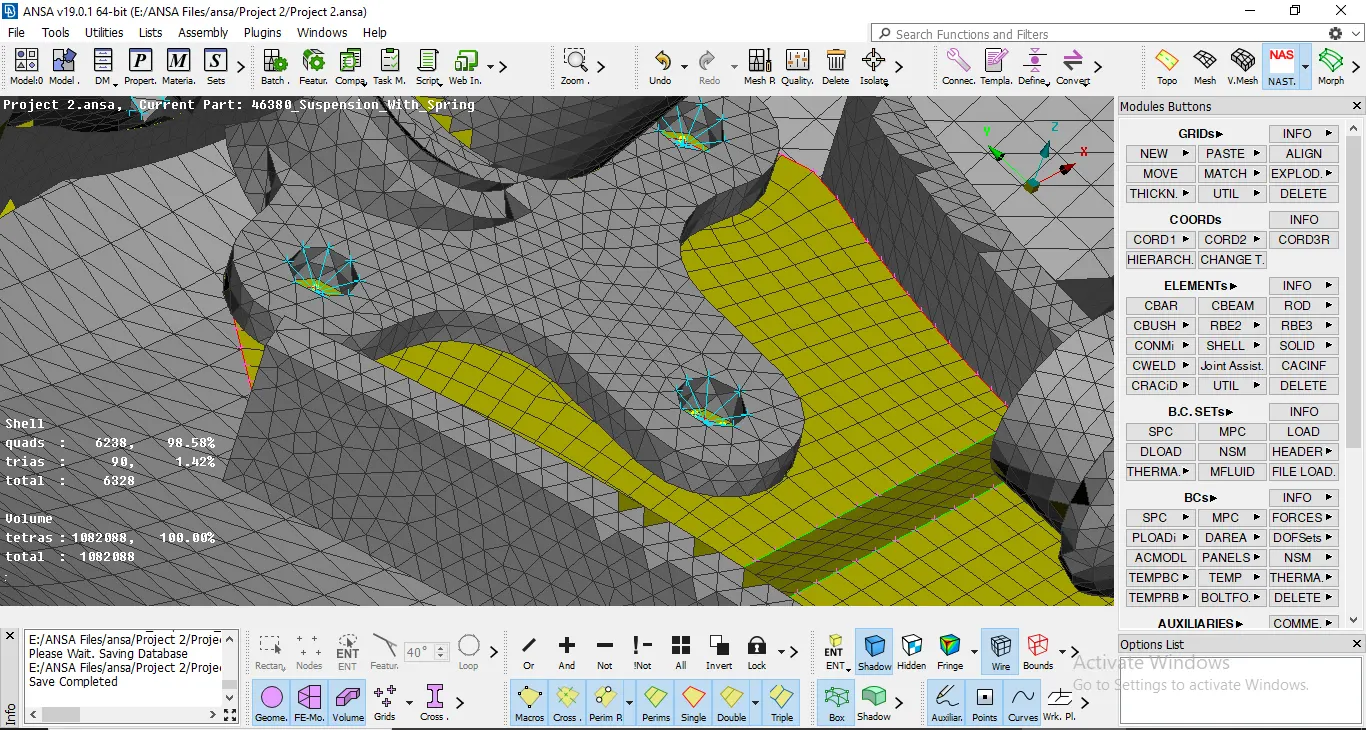
Connections on the model.
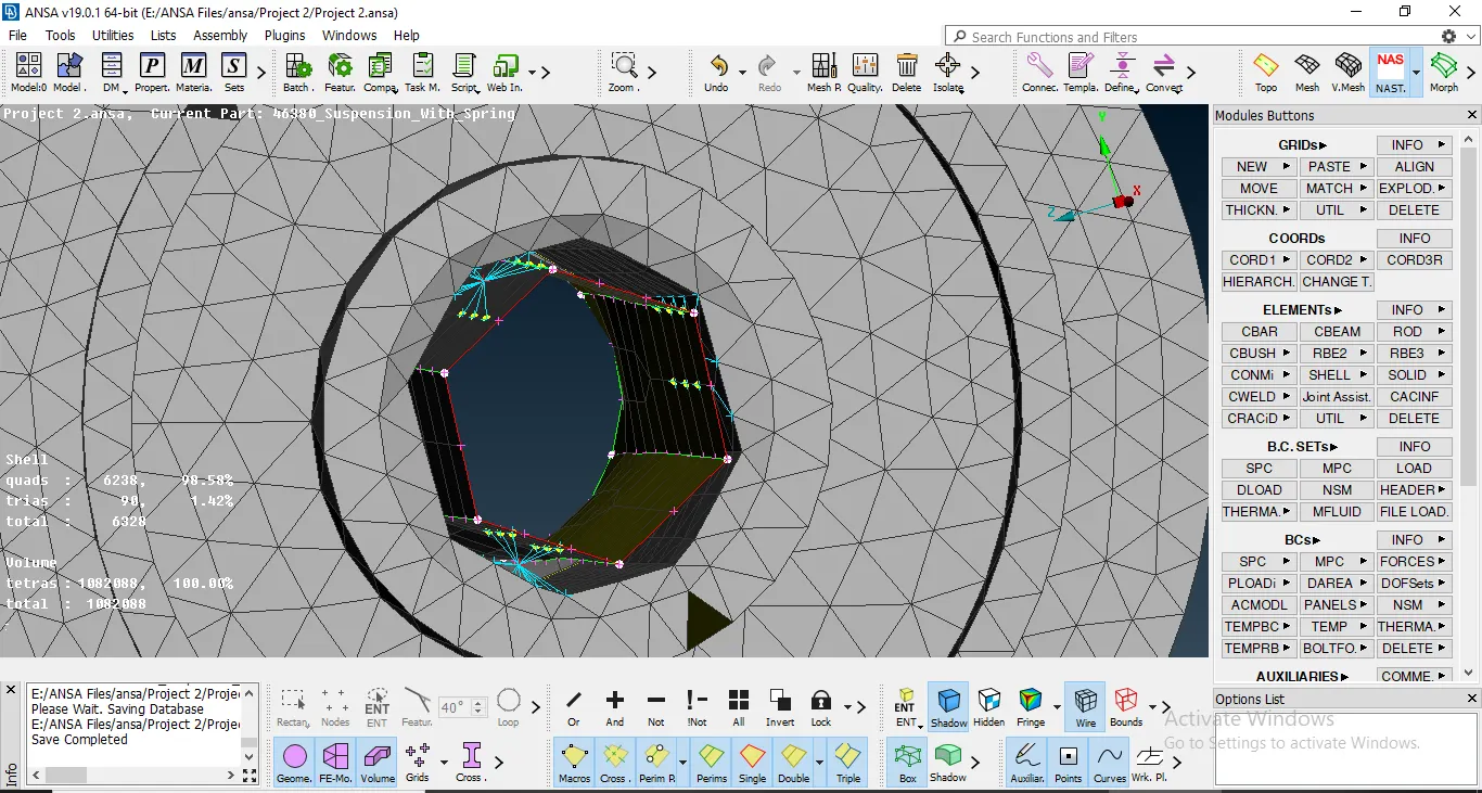
Connections.
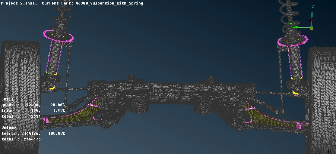
8. Then after the entire model is completed, I mirrored the model using the Transform option. Under this option, I used the symmetry command and mirrored the model using the 3 point option.
- Learning Outcomes: 1. Complete review of the Volume Meshing procedure.
2. Understanding the connections in the model.
3. How to do a good Geometry clean up.
4. How to remove and resolve Off Elements.
- Conclusions: In conclusion, I would like to state that this project helped me in getting an review of the entire Volume Mesh and the Connection procedures required to mesh a model.