Week 6.1 - Setting up a model (Electronic enclosure)
AIM : The objective of the project is convert CAD geometry into simplified geometry for the Icepak and then run the simulation, by using tools in Spaceclaim & the components in Icepak.
INTRODUCTION :
Geometry Simplification is one of the main process in a CFD simulation project. It is important for the the optimum simulation i.e. a perfect balance in mesh count, computation requirement and computation time while maintaining the accuracy of the analysis. Small Fillet/chamfer curves, very small components not acting in the case's physics can be removed for reducing mesh count. Complex geometry can be break down into simpler form for reducing no. of mesh cells as well as improving mesh quality.
For Ansys CEPAK being natively designed for the electronic cooling CFD, the CAD geometry must be converted into primitive Icepak shapes using the commands available in SpaceClaim, inorder for the better recognition and assignment of the components.
Electronic cooling is required to remove the waste heat produced by computer components, to keep components within permissible operating temperature limits. Components that are susceptible to temporary malfunction or permanent failure if overheated include integrated circuits such as central processing units(CPUs), chipset, graphics cards, and hard disk drives.
STEPS :
1) After the given CAD model of an electronic enclosure assembly is imported in SpaceClaim, the bodies which have no major effect on the analysis/simulation and its results are removed from the geometry inorder to simplify it. An analyst can classify the geometries into the following categories -
-
Focus bodies - These are the bodies which will take major role in the analysis or here heat transfer system, like source, conduction path, heat sink, openings, fans/air flow, flow obstacles, etc.
-
Necessary bodies - The bodies which will have some effects on the focus bodies.
-
Peripheral bodeis - These bodies may or may not affect the focus bodies.
-
Dispensable bodies - The small bodies on the assembly which has no effect on the physics of the system, these bodies are completely neglected.
2) Removing extra surfaces or portions or parts which are not imprtant for the thermal analysis.
Uneccesary parts like the screws in the following picture, which are not acting in thermal analysis can be deleted from the parts tree.
With the help of split body tool we can spilt the extended not required portion of the part and delete it.
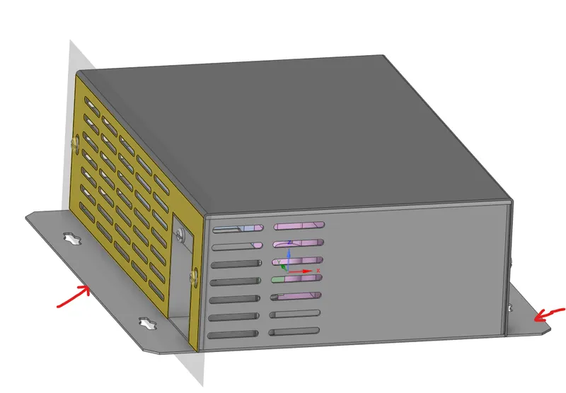
3) Deleting unecessary rounds, curvature, fillets/chamfers.
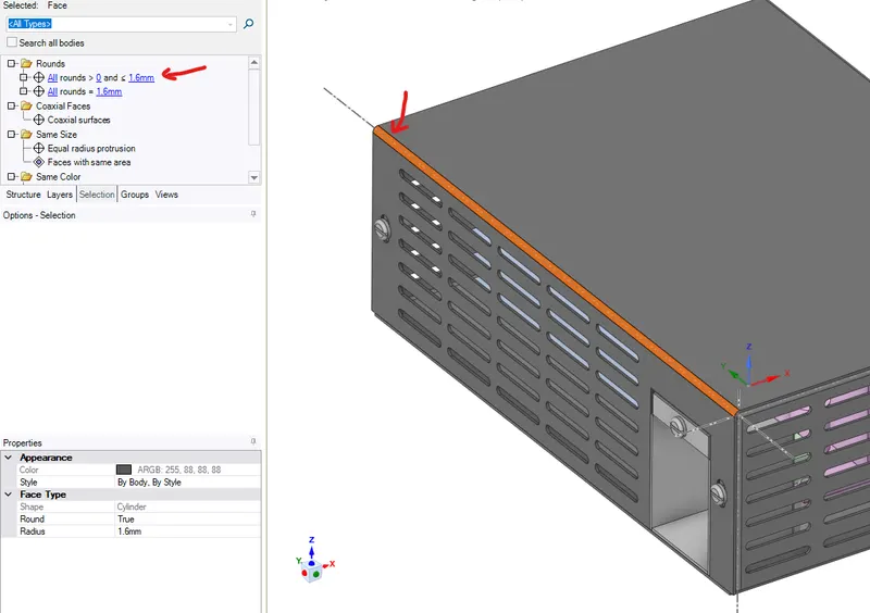
4) Filling the gaps which are not required in thermal analysis.
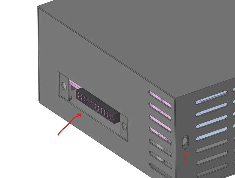
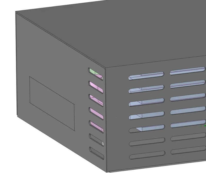
5) Splitting/improveing the irregularities in the imported geometry.
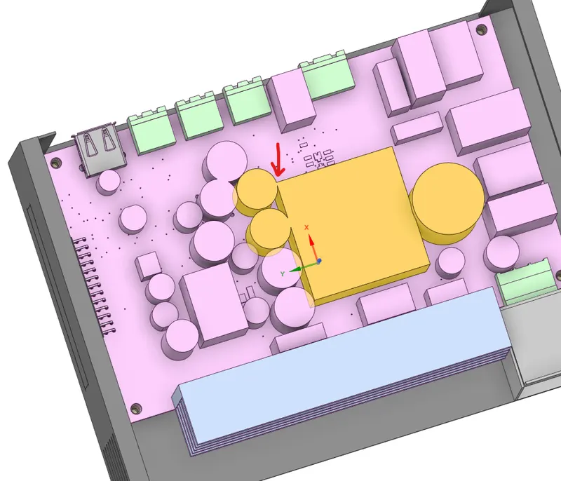
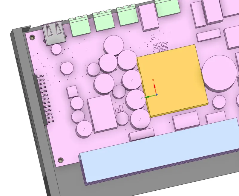
6) Simplifying bodies using Icepack Simplify tool in spaceclaim.
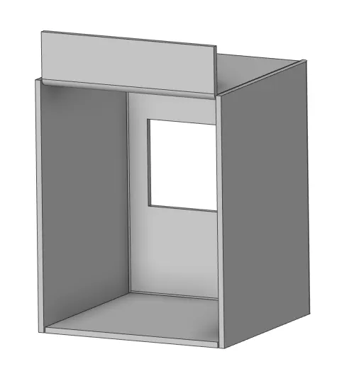
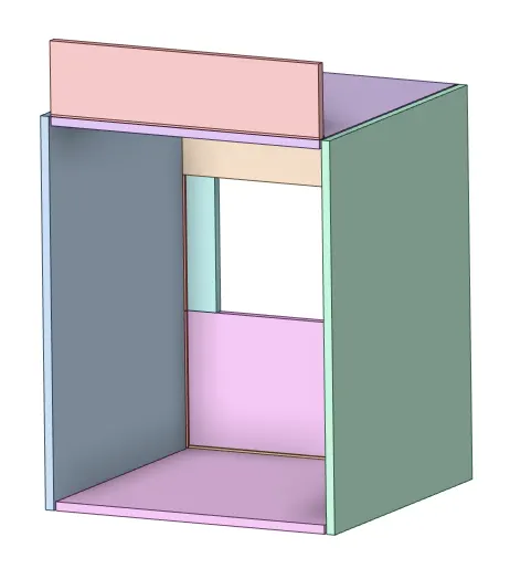
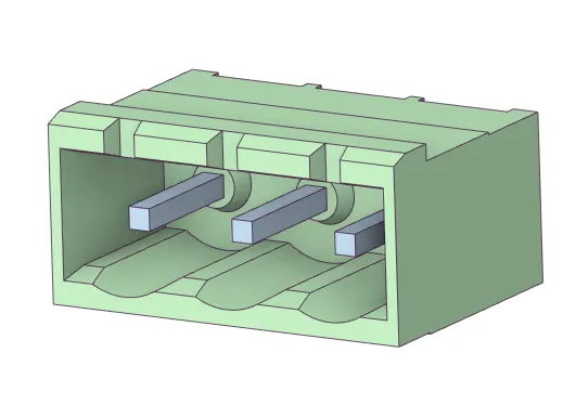
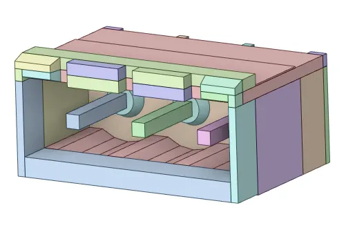
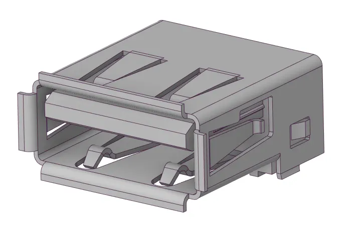
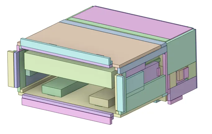
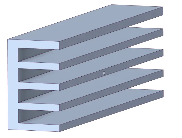
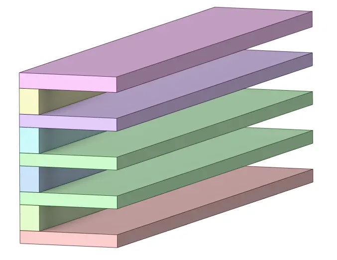
There are four different levels of simplification from 0-3 as shown below-
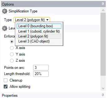
Each level increase the accuracy of the object's body shape for the conversion, which can selected by the analyst/user as per the simulation case.
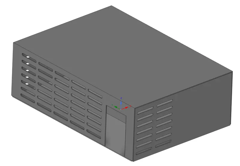
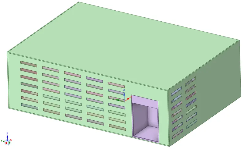
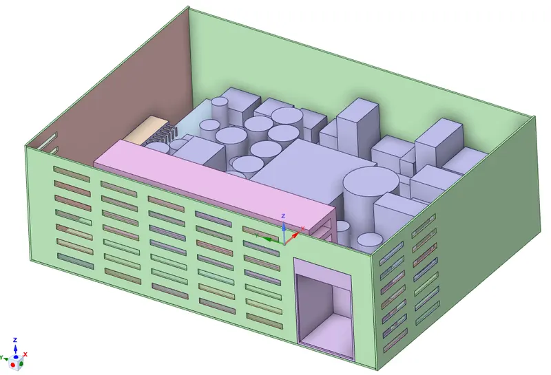
Creating Grills/openings/fans as available in the geometry case.
7) Checking the interference between the object bodies and modifying it.
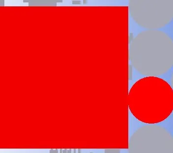
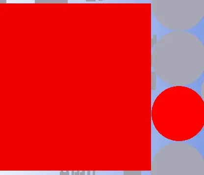
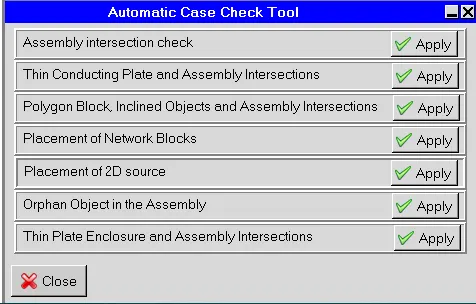
Before moving on from Geometry cleanup and loading, certain checks are performed to ensure that the correct physics is defined. One of the important check to avoid errors, is the interference check in which the geometries interfering with each other are identified, either manually or using Macros. In order to pass this check, the interfering geometries are moved apart manually in Icepak
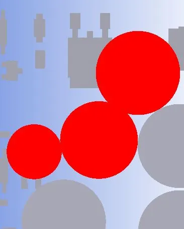
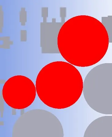
Case check tool in Macros options-

4) MESHING
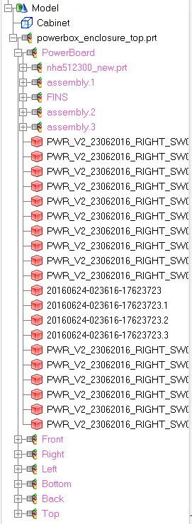
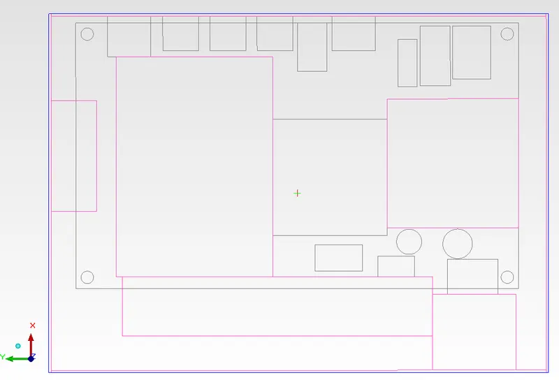
-> Loading Geometry/the given case setup from spaceclaim
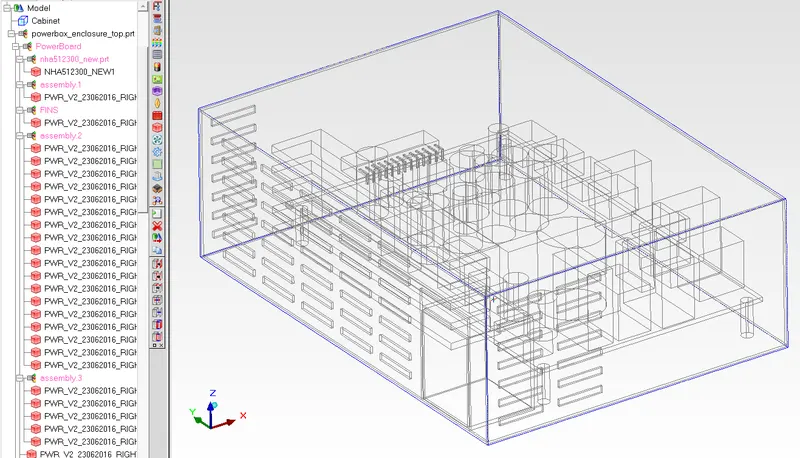
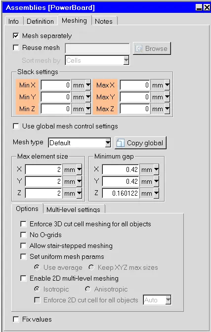
-> Creating Mesh assembly and non-conformal meshing
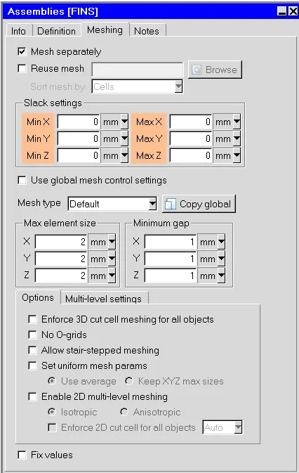
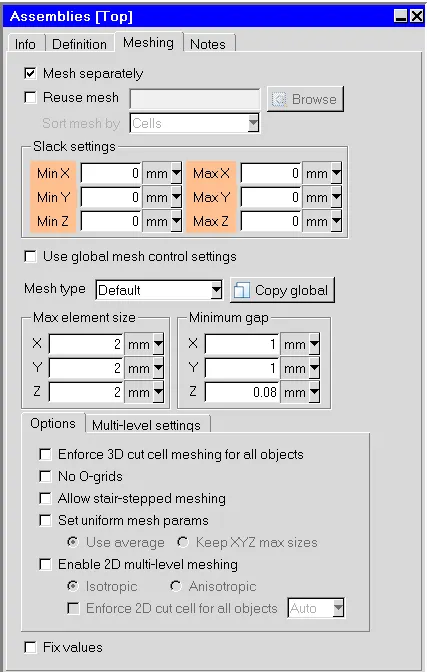
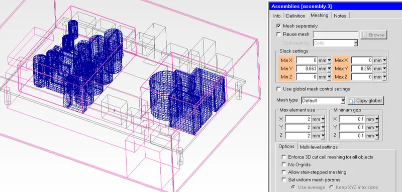
5) Mesh Quality Parameters
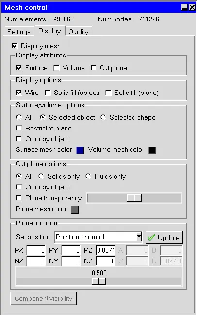
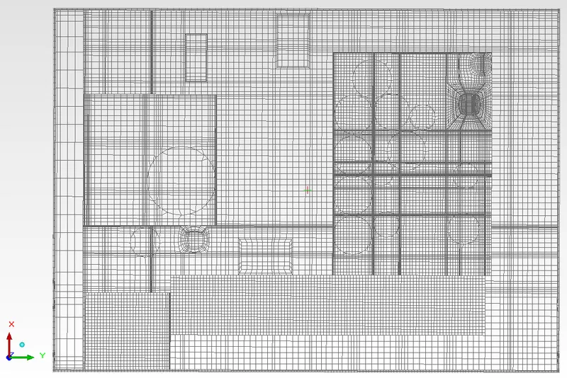
Following is the surface mesh of the Case Setup -
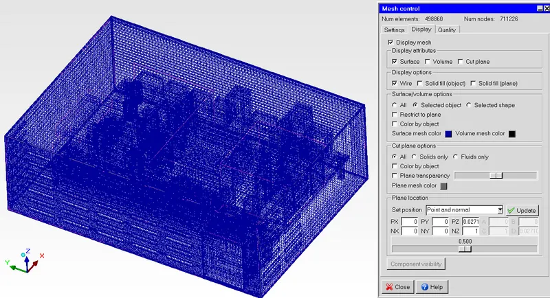
Following is the visualising the mesh inside the cabinet-
- Cut plane of XY plane at 50% of the cabinet in Z-direction from origin (Top Plane)
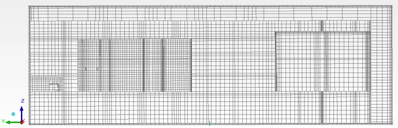
- Cut plane of YZ plane at 50% of the cabinet in X-direction from origin (Front Plane)
- Cut plane of XZ plane at 50% of the cabinet in Y-direction from origin (Right Plane)
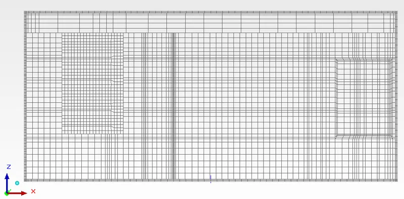
We can the mesh quality is very satisfied. 90% of the mesh cell are lying on good quality range.
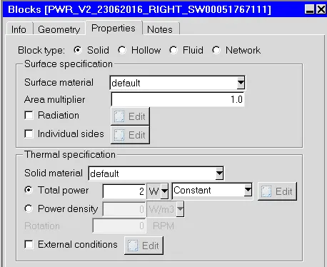
Component Properties & Settings -
Sources and their properties -
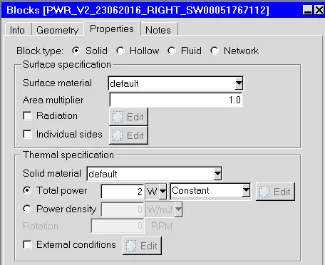
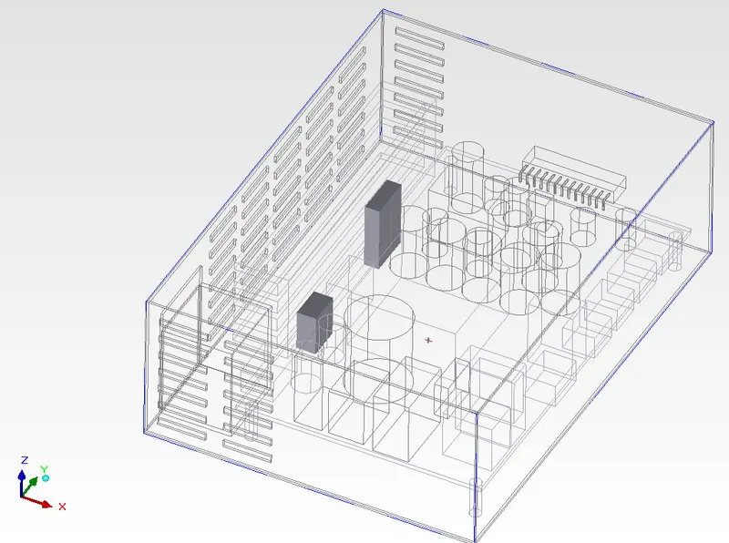
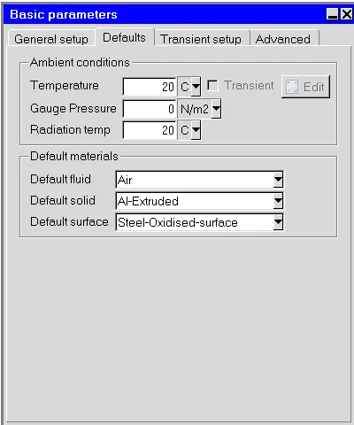
Solver Settings -
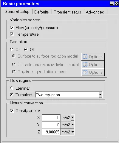
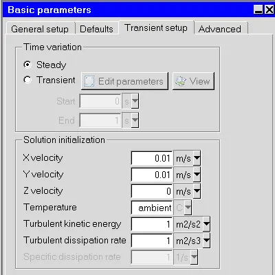
Radiation solver has been disabled because majority of heat transfer is happening through convection.
Inorder to capture the turbulence flow conditions we have chosen two equation model option i.e. K-epsilon turbulaance model.
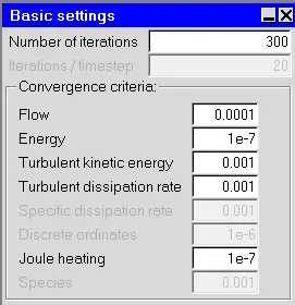
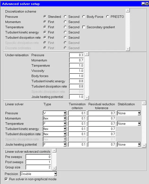
The solver setting majorily have kept default. and the discretization schemes are kept 1st order in-order to get stable first cut simulation.
POST PROCESSING :
Outputs
Residuals -
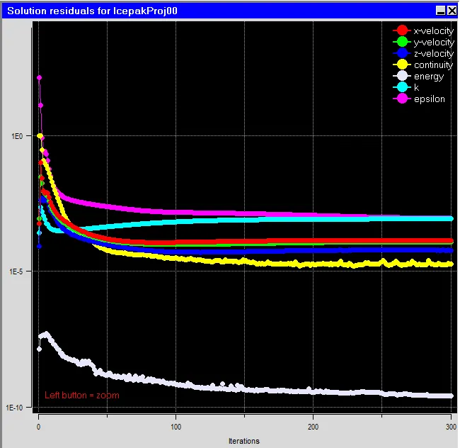
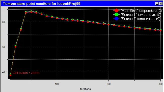
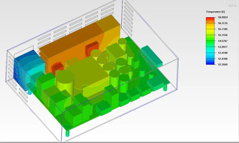
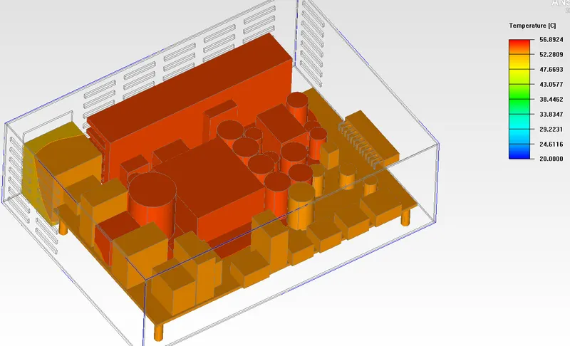
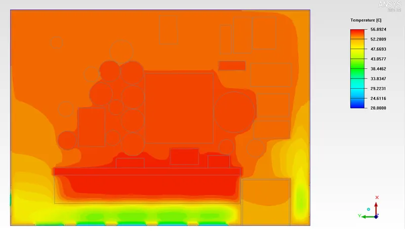
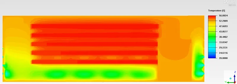
Temperature Contours -
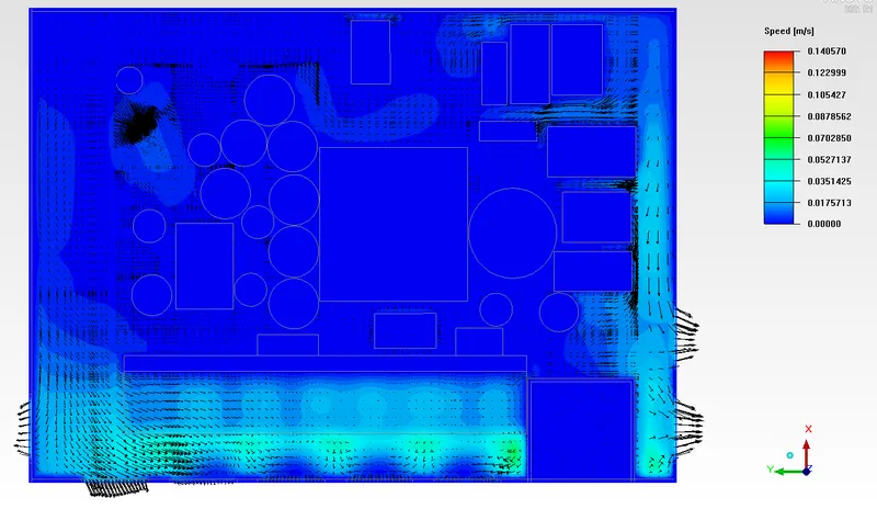
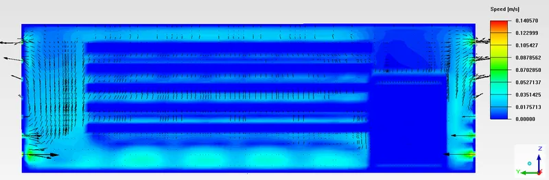
Contour and Streamline Visulization of Velocity of the fluid -
RESULTS :
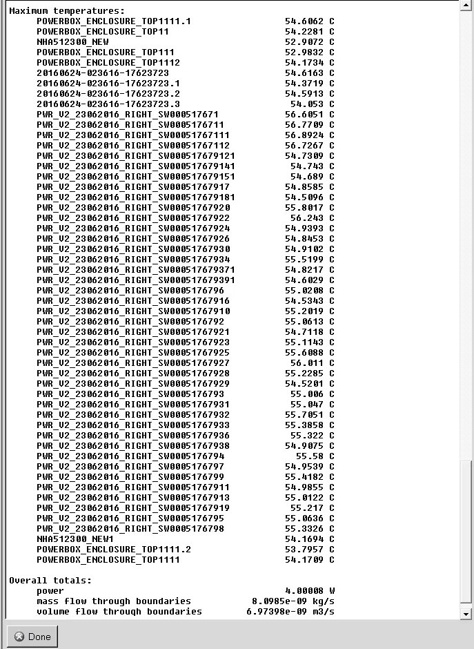
The Following are the results of the simulation, generated simulation report from the ICEPAK software Showing Various characteristic values of the simulation and the max. temperatures of the different bodies acting in the simulation -

CONCLUSION :
We have successfully performed the simulation analysis for the Electronic enclosure.
The maximum temperature within the computational domain is 56.892 deg.C. at the sources.
The maximum air velocity within the computational domain is 0.1406 m/s.
The required numerical and physical settings have been given to the model and taken the required vector plots, temperature, speed, and parametric change in object faces.
This is the first cut simulation the residuals less than `10^-3`. We can make more refined mesh and the stable 2nd order discretization
for the more accurate results.