Week 6.1 - Setting up a model (Electronic enclosure)
Setting up a model (Electronic enclosure)
Aim: To perform the flow and thermal simulation on a power board assembly.
Objective:
- The first step is to simplify and convert the given CAD geometry from SpaceClaim to ICEPK objects.
- After converting, we properly mesh the board in ICEPK.
- In which the above two steps have already been done in the 3rd and 4th challenges.
- Then we have to set-up and post-process these results.
GIVEN GEOMETRY
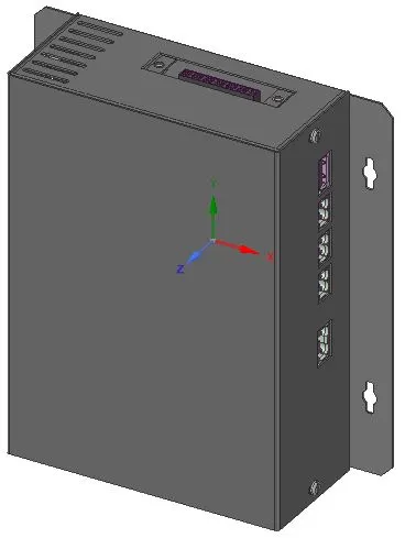
The image attached below shows the given CAD geometry of an electronic enclosure.
Mesh Generation:
After converting the unnecessary components in the geometry into an inactive mode
The final geometry has been made for conformal mesh generation.
Conformal mesh
- To know when the conformal mesh is concerned. Generally, if we dealing with a region consisting of more than one part and we need to mesh each of these parts separately then we have to take advantage of conformal mesh.
- If we just mesh each part separately and then combine them without using conformal mesh, chances are that the mesh will have either of the two problems.
Cut plane through the x-axis:
Cut plane through the y-axis:
Cut plane through the z-axis:
Mesh surface for the domain:
We Check for quality, Depending on the cell types in the mesh (tetrahedral, hexahedral, polyhedral, etc.), different quality criteria are shown below.
Face alignment:
The maximum face alignment that has been obtained in the geometry was one in the domain and the detailed profile of the face alignment is shown below.
Volume:
Skewness:
A general rule is that the maximum skewness for a triangular/tetrahedral mesh in most flows should be kept below 0.95, with an average value that is less than 0.33.
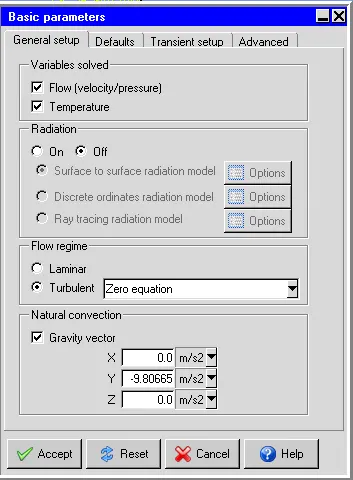
The general setup for basic parameters :
Basic parameters and choose the Zero equation turbulence model for the flow regime in the General setup tab.
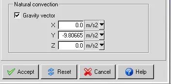
Set up the gravity vector :
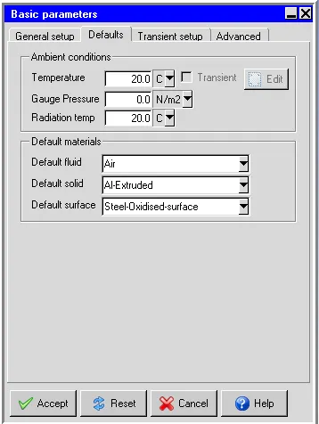
Defaults parameters :
Transient setup parameters
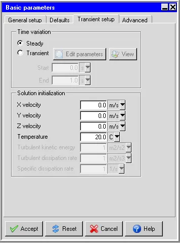
A steady-state simulation was considered in the simulation.
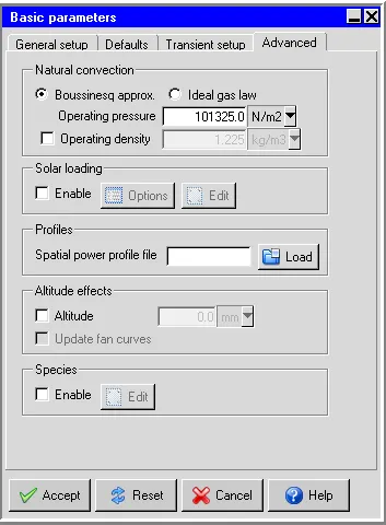
Advanced parameters in basic settings:
Set no of iterations and convergence criteria:
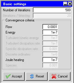
The total number of iteration was set to be 500 iterations and coming to the convergence criteria the flow was set to 0.0001 and joule heating, the energy was 1e-7, and the turbulent kinetic energy and turbulent dissipation rate were 1e-7
Parallel setting:
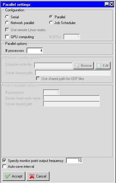
Advanced solver setup:
Examine and post-process the results:
Residual plot:
The residuals for the following equations are plotted against the number of iterations:
i. Continuity equation
ii. X-Momentum equation
iii. Y-Momentum equation
iv. Z-Momentum equation
v. Energy
The image attached below shows the residuals plotted against the number of iterations.
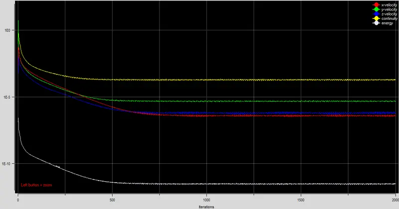
The plot shows that the residuals don't change appreciably after 750 iterations thereby indicating that the solution has reached a steady state. For the current project, the simulation is run for 2000 iterations even though the solution has already reached a steady-state after 750 iterations. Henceforth the simulation results after 2000 iterations are considered as steady-state results.
Temperature-monitor plot
The image attached below shows the outputs from the two temperature monitors as a function of the number of iterations.
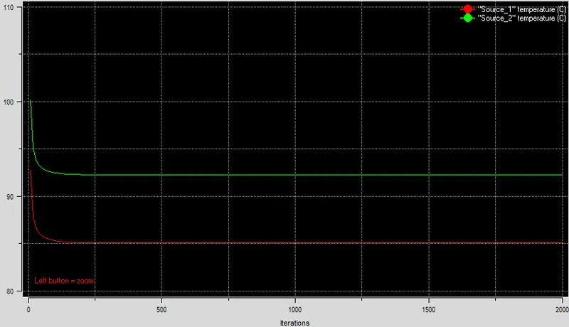
The image shows that beyond 250 iterations there is no appreciable change in the average surface temperatures of the two heat sources in the model. Hence according to the temperature-monitor plot also the simulation results after 2000 iterations can be considered as steady-state results. The following steady-state temperatures are attained by the two heat sources in the model:
i. Source_1: 85.06 deg. C
ii. Source_2: 92.24 deg. C
3. Velocity contours
The image attached below shows the steady-state velocity contours plotted on the Z-plane through the centre.
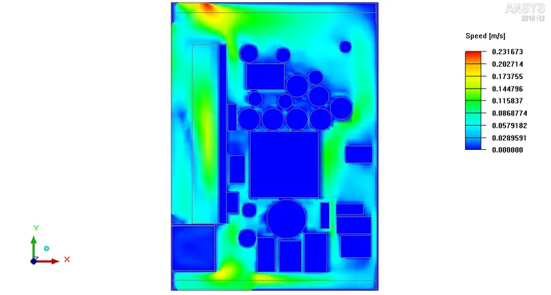
The contour plot shows that the air inside the enclosure assembly is in motion and the electronic components on the PCB (capacitors, heat-sink etc.) affect its flow. According to the contour legend, the maximum air velocity within the computational domain on the Z-plane through the centre is 0.232 m/s.
Velocity vectors
The image attached below shows the steady-state velocity vectors plotted on the Z-plane through the centre.
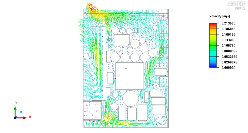
The vector plot clearly shows the direction of motion of air within the computational domain, as it (air) enters into the enclosure assembly through the bottom grille, moves over the electronic components on the PCB and finally leaves through the top grille. This upward motion of air against gravity (which is directed along the negative Y-axis) can be attributed to natural convection. The velocity vectors also clearly show the recirculation of air through the side grille.
Temperature contours
The image attached below shows the steady-state temperature contours plotted on the Z-plane through the centre.
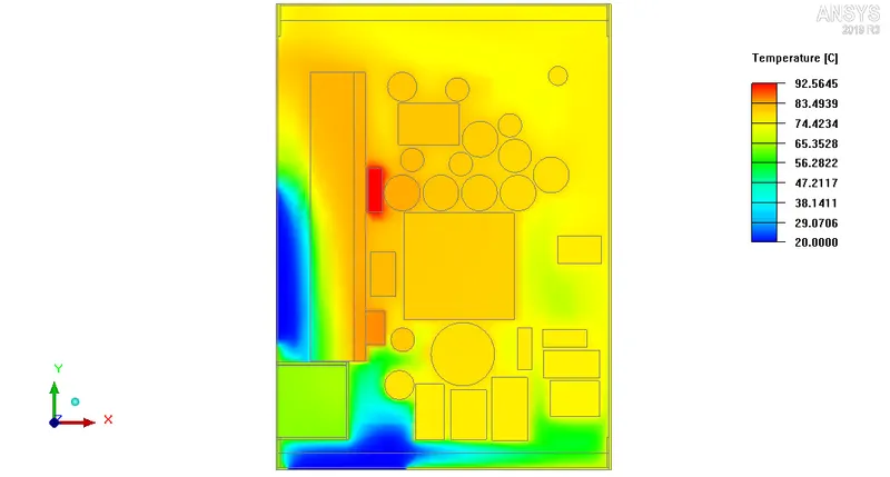
The contours show that the air inside the enclosure assembly is at a higher temperature due to convection heat transfer between the electronic components and the air. The hot air rises up against gravity (directed along the negative Y-axis) and finally leaves the enclosure assembly through the top grille and the upper part of the side grille. This drives cool air (at ambient temperature) inside the enclosure assembly through the bottom grille and the lower part of the side grille. The cool air picks up the heat generated by the model, rises up and leaves through the top grille and the upper part of the side grille. In this manner, natural convection drives air through the enclosure assembly and allows for effective thermal management of the same (enclosure assembly).
Object face temperature contours
The image attached below shows the steady-state object face temperature contours plotted on all the objects in the model that are located within the housing except the PCB supports.
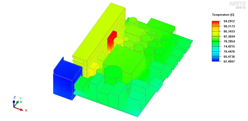
The contours show that the highest steady-state temperature is attained by one of the two heat sources in the model. Due to the thermal dissipation of heat sources, the objects that are located closer to them are hotter as compared to the objects that are located far away.
Particle traces
The image attached below shows the steady-state particle traces for 60 particles distributed uniformly within the computational domain.
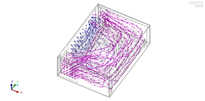
The image shows the pathlines traced by the air particles originating at the bottom grille (shown in pink colour) and the side grille (shown in blue colour), at a steady-state. The pink-coloured particle traces show that the air particles entering into the enclosure assembly through the bottom grille flow over the electronic components on the PCB and finally leave through the top grille. Similarly, the blue coloured particle traces show that the air particles entering into the enclosure assembly through the side grille flow over the heat-sink and leave through the upper part of the side grille. The animation attached below shows the steady-state particle traces (coloured by temperature) for 60 particles distributed uniformly within the computational domain. The colour of the particle trace at a particular location indicates the temperature of the air particle at that location.
Conclusion:
- The simulation is performed for the power board assembly using the Non-conformal mesh.
- The model includes some solid components, a heat sink, as well as by air driven by forced convection through the openings from one side. Separately mesh assemblies will be employed to reduce the overall mesh count.
- The required numerical and physical settings have been given to the model and taken the required vector plots, temperature, speed, and parametric change in object faces.