Sphere Pressing on a Plate Using Ansys Workbench
OBJECTIVE
- To assign the structural steel material to the sphere and structural steel (non-linear) to the plate.
- To assign the symmetry for solving the problem, as it is a quarter model.
- To assign the frictional contacts.
- To mesh the model.
- To apply the boundary condition.
- To collect the results and interpret.
PROCEDURE
This simulation was a quarter analysis of the sphere. The quarter part of the model can be seen in the figure below. The simulation seems to be static non-linear, therefore, it had to solve using the Static Structural module of Ansys. Next, the material had to define before proceeding further. Using Engineering data, all the required materials viz. structural steel, and structural steel (non-linear) were imported.
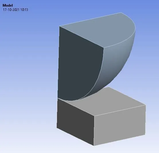
Figure 1: Sphere and plate model in Ansys GUI.
The Mesh section of the Static Structural module was opened. In that, the material of the sphere was set to structural steel, and the material of the plate was set to structural steel (non-linear).
Now, because the model was a quarter part of the whole model, symmetry was defined to it for solving the problem for the whole model using only the quarter part of it.
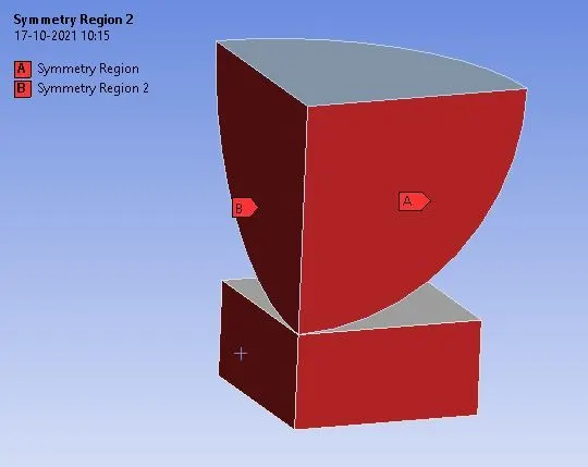
Figure 2: Symmetry defined for the model.
Further, the automatically created contact cards were deleted, and a separate contact card was created for the sphere and the plate, with the frictional behavior, and coefficient of friction of 0.74 (according to the RoyMech tribology table).
Next, the mesh was created for the model, as shown in the figure below.
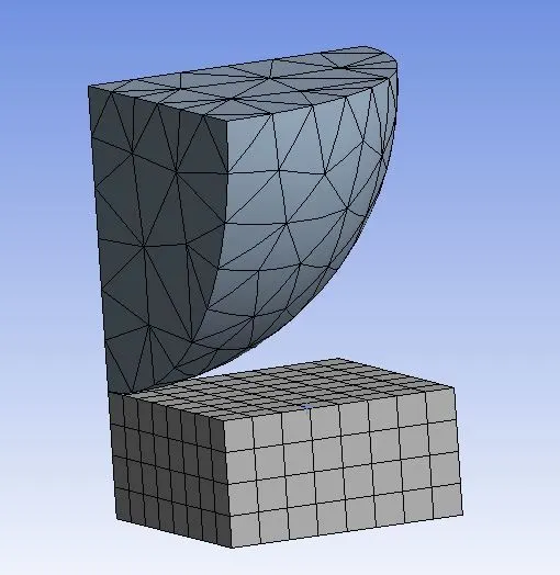
Figure 3: Meshing of the model.
The analysis was solved in 4 steps. In boundary condition, the plate was fixed, and the displacement of 4 mm (in steps) was applied to the sphere as shown in the figure.
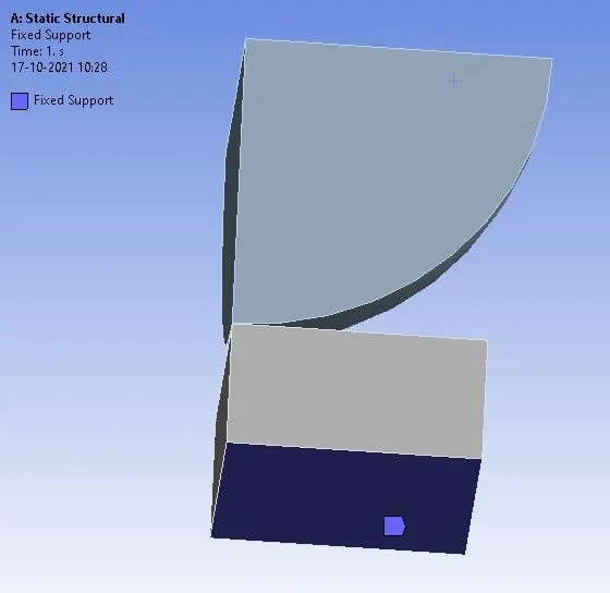
Figure 4: The base of the plate was fixed.
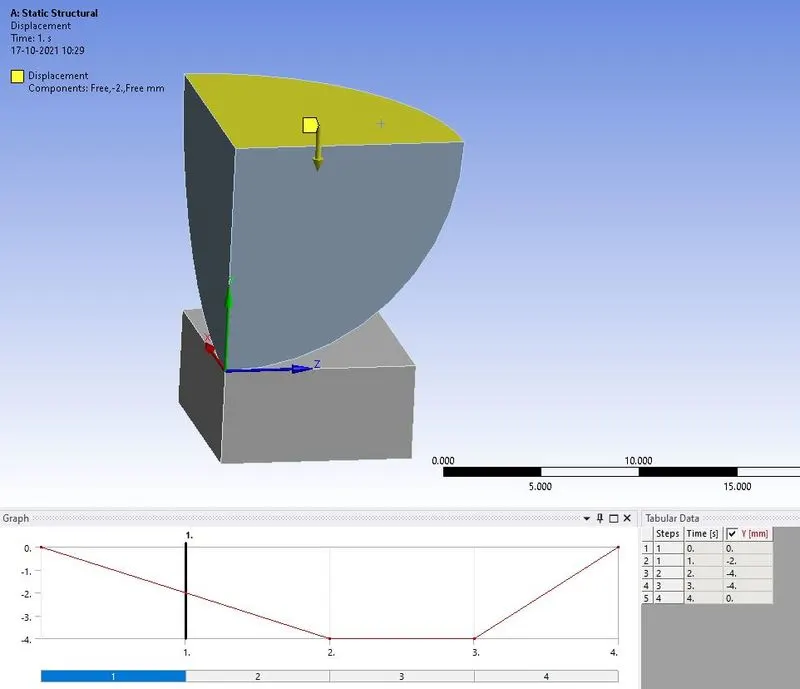
Figure 5: Displacement applied to the sphere.
In the solution, the results were requested for the directional deformation, equivalent stress, and equivalent strain for the plate. All the results are shown in the figures below.
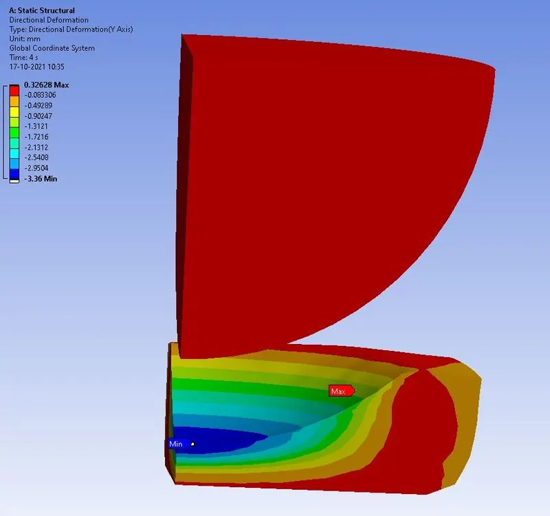
Figure 6: Directional deformation in the direction parallel line of action of displacement, with maximum deformation of 0.32638 mm.
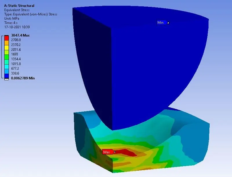
Figure 7: Equivalent stress in the model, with maximum stress of 3047.4 MPa.
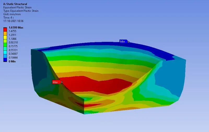
Figure 8: Equivalent plastic strain in the plate with the maximum plastic strain of 1.6599 mm/mm.
CONCLUSION
This simulation was performed to study the procedure of simulating the symmetric model. In this model, a sphere was pressed on a non-linear structural steel plate. After pressing it was found that the plate had undergone plastic deformation. With 4 mm of displacement to the sphere, the plate deformed with a strain value of 1.6599 mm/mm.