Week 5 Sphere pressing on a plate
-
Objective: To perform simulation of a sphere pressing a flat plate and confirm whether there is plastic deformation in the plate.
-
Procedure:
The geometry has 2 planes of symmetric portion. For symmetric body with symmetric boundary conditions, we can use the property of symmetry and only perform analysis on ¼ portion of geometry. This will give
the same result as the analysis performed on full geometry, but due to reduced geometry, the computation time and CPU resources required is significantly reduced. Open the static structural analysis system in
the Project schematic. The material used for analysis is Structural Steel for the sphere and Structural Steel ( Non Linear) for the plate. These materials are added to the material library in Engineering Data.
Now proceed to import the geometry. Import the Geometry. Open the Geometry in SpaceClaim. Ensure the geometry is properly imported by doing quick visual inspection. The geometry is properly imported as
observed below:

Update and open the mechanical module. Assign the material Structural Steel to the sphere and Structural Steel Non-Linear to the plate. Now, we need to define the contact between the Sphere and the plate. For
Contact Bodies, sphere outer surface is selected, and for Target Bodies, plate top surface is selected. There will be friction between the bodies when they come in contact. Therefore, Frictional type contact is
defined with co-efficient of friction 0.74. This value is obtained from the roymech tribology table.
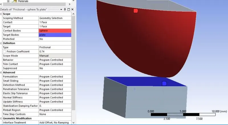
The default mesh generated by the solver is found to be good enough to run the simulation, so default mesh is accepted.
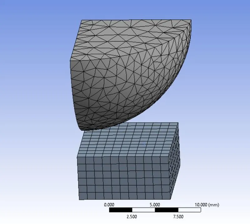
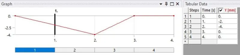
The sphere is to be displaced by 4mm downwards and press the plate. The displacement is to be applied in 4 steps. In these four steps the sphere has to travel the 4 mm distance and also retract after pressing
the plate. Go to Analysis settings and enter number of steps = 4. Switch the Solver Type to Direct and turn on the Larger Deflection. To prevent rigid body motion, fix the plate at the bottom surface. Go to Static
Structural > Insert > Fixed Support. Fix the plate at the bottom surface.
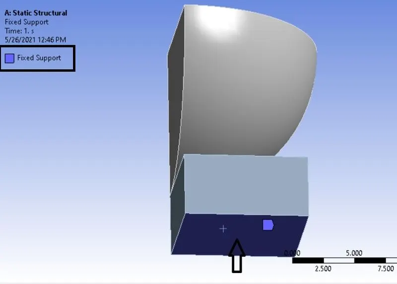
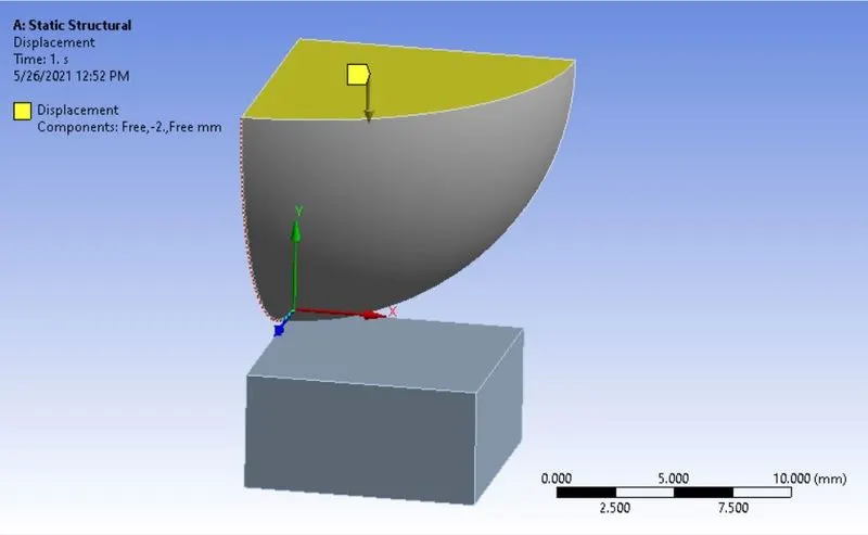
Now insert the displacement for the sphere. Go to Static Structural > Insert > Displacement. Select the top surface of the sphere and apply displacement of 4 mm in the -ve Y direction and also retract the sphere
after pressing 4 mm. Only after retraction, we can confirm if the plate is plastically deformed or not. Give the magnitude for Y displacement in Tabular format as shown below.
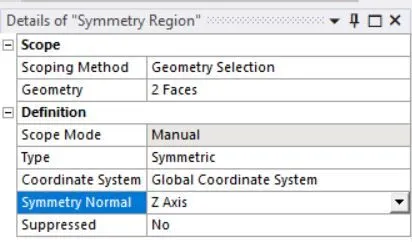
Now before listing the required results, we need to first define the symmetric regions of the geometry. Go to Model > Insert > Symmetry. Right click on the Symmetry > Insert > Symmetric Regions. Select the
following surfaces. As per the co- ordinate system, the Symmetry normal is Z axis.
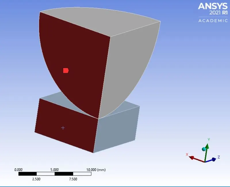
Similarly, define the other symmetric region of the geometry as shown below.
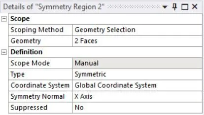
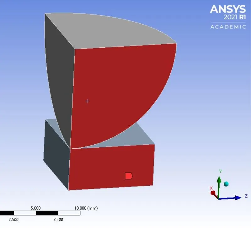
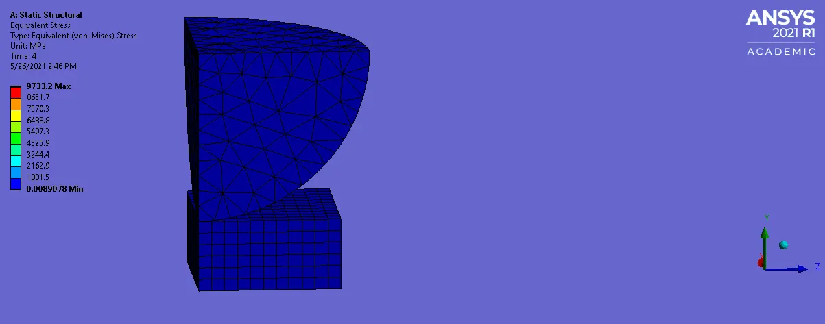
Now, list the required results. The directional deformation for Y axis, equivalent strain of the plate and sphere and equivalent stress on the plate are the results that are listed. Run the simulation and examine the
results.
- Results:
Animation file for the simulation:
Strain in the plate:
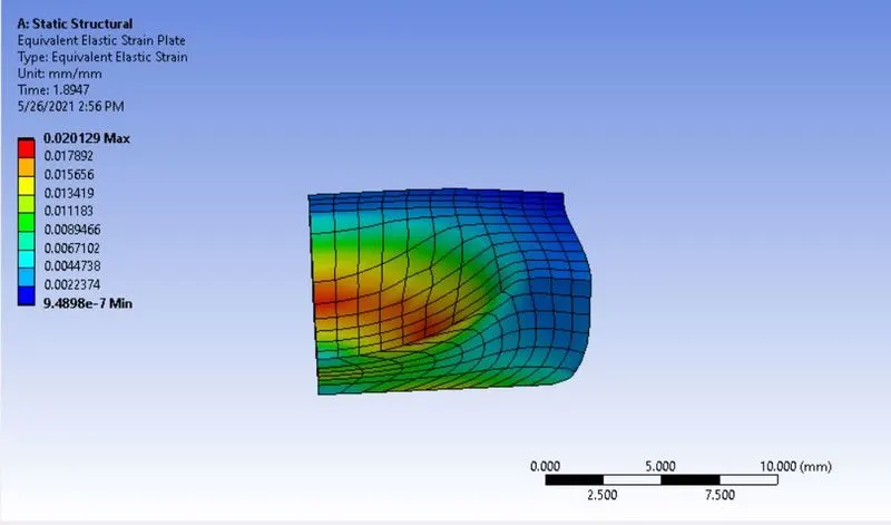
Max strain of 0.020 is observed in the plate where the sphere impacts.
Strain in the sphere:
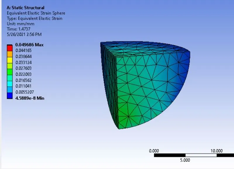
As seen above, max strain of 0.049 is observed.
Stress in the plate:
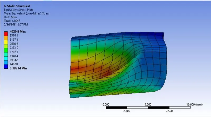
Max stress of 4020.8 Mpa is observed at the impacting portion.
Deformation in Y direction:
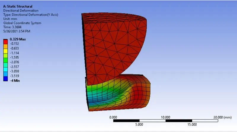
Max deformation of 0.32 mm and -ve deformation around of 4 mm is observed.
- Observation: It is clear from the animation file, that when the sphere retracts, the plate remains deformed which indicates that the plate is plastically deformed. Max stress in the plate is observed at the
impact region.
- Conclusion: Thus, the given simulation is completed using reduced geometry portion as the geometry and the loading conditions are both symmetric. The plastic deformation deformation of the plate is also
confirmed.