Week 5 Sphere pressing on a plate
Sphere Pressing on a Flat plate
Objective
To perform the Static Structural analysis and also simulate a sphere pressing on a plate.
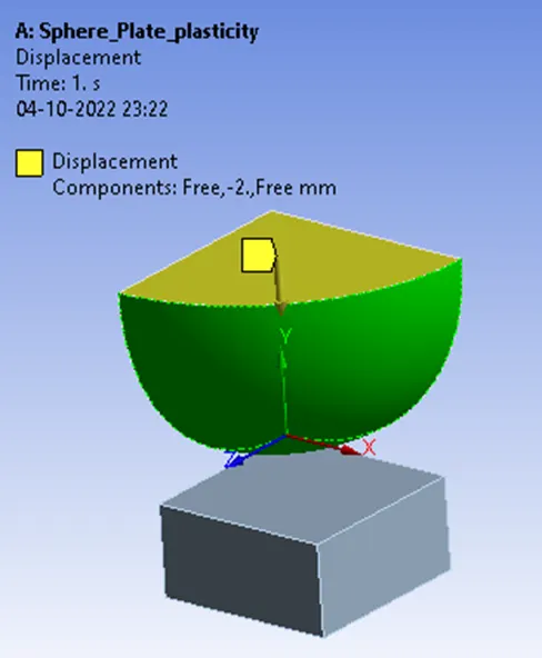
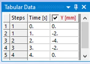
Use Structural steel for both sphere and plate but the material of the plate must be Non-Linear. Press the sphere onto the plate 4mm downwards and retract it in such a way that the plastic deformation must be captured.
CAD Model of the Sphere and Plate is incorporated for Analysis (Front view & Isometric view)
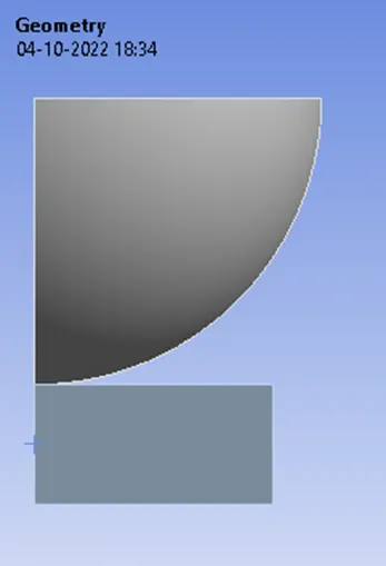
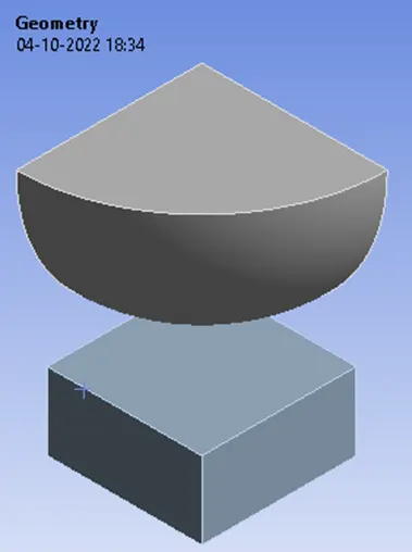
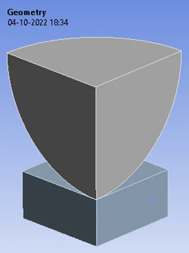
Using this case we will learn how to capture the Plastic deformation that occurs on the Flat plate because of the Sphere pressing on it. So before we begin with the Simulation setup as a good FEA engineer one should be able to reduce the computational time required to run a simulation, that in case if there is a Symmetric region where you can simplify the geometry further and get results for a particular region and mirror it to the other side to get the whole geometry.
For ex if we have a square plate and if we are looking at the heat conducted on all four sides of the geometry but if the loads are all equal we can very well take half of the geometry and run the simulation, with this result we can mirror it to the other side to get the whole geometry.
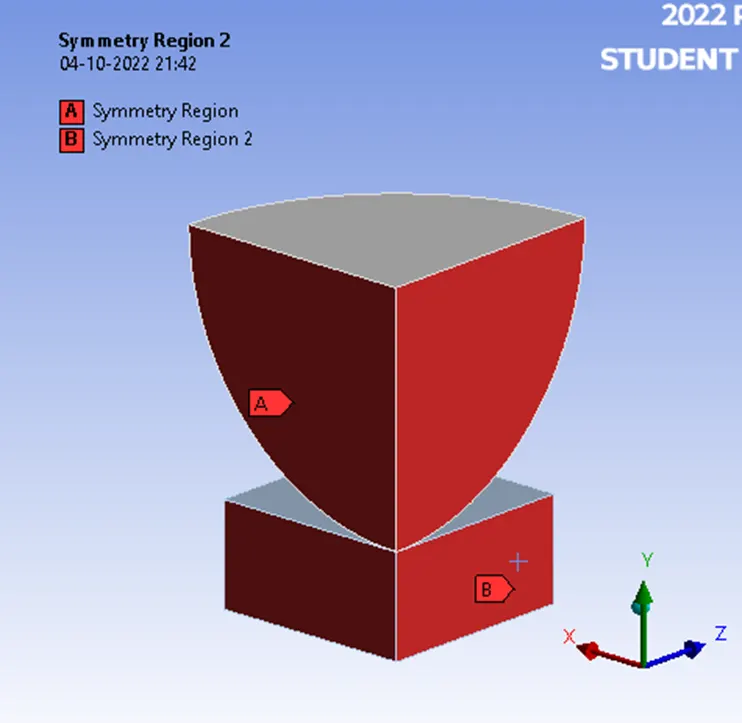
In our case, we have a whole sphere and there is a flat plate below it, we are going to let the sphere press onto the flat plate until it crosses the elastic region i.e the deformation we get from the simulation will be in the plastic region. So here since the geometry has two planes of Symmetric region, we will be using only a quarter portion of the whole Geometry.
Material Properties have been taken from Engineering Data Sources of Ansys Workbench.
|
Material Specifications for |
Density (Kgm^-3) |
Young’s Modulus [MPa] |
Bulk Modulus [MPa] |
Shear Modulus [MPa] |
Yield Strength [MPa] |
Tangent Modulus [MPa] |
|
The sphere as Structural Steel |
7850 |
2E11 Pa or 200000MPa |
1.6667E11 Pa or 166670MPa |
7.6923E10 Pa or 76923 MPa |
2.5E8 Pa or 250 MPa |
|
|
Flat plate as Structural steel NL |
7850 |
2E11 Pa or 200000MPa |
1.6667E11 Pa or 166670MPa |
7.6923E10 Pa or 76923 MPa |
2.5E8 Pa or 250 MPa |
1.45E9 Pa or 1450 MPa |
Symmetry
If the geometry, material orientation, loading and expected response all exhibit symmetry about the same planes, we can take advantage of planar symmetry and only model a portion of the actual structure to reduce the analysis run time and memory requirements. Using symmetry regions in Ansys mechanical can give more accurate and more computationally efficient solutions.
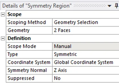
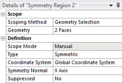
Here the symmetry region is selected based on the plane normal to the face i.e. if you are choosing x plane as symmetry region then symmetry normal to be Z Axis and similarly if you are choosing z plane as symmetry region 2 then symmetry normal to be X-Axis as shown below.
Connections
Contact Settings:
Initiating contact settings is crucial for the designer and end-user since the setting of contact surfaces is at the discretion of the designer as to what to ignore and which to consider. Here the Sphere and Flat plate are in constant contact to undergo dynamic attributes of stresses, strains, and deformations as such the designer have to closely observe and predict the cognitive analytical ability to consider it as crucial for setting the contact region and ignoring other factors for efficient (i.e. Saving Time and Energy) Way of Analysing.
Contacts allowing separation (e.g. frictional contacts) are non-linear contacts. For FE models with non-linear contacts, an iterative process is involved to obtain a solution and therefore non-linear contact analyses are more computationally demanding.
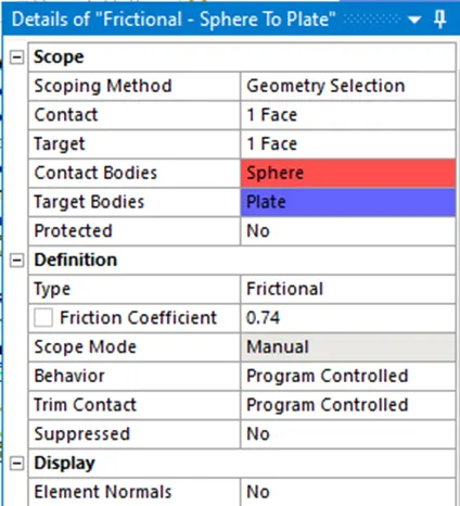
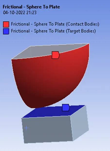
Frictional- Sphere to Flat plate
This state is known as “sticking.” The model defines equivalent shear stress (shear stress refers to cases where the deforming force is parallel to a surface) at which sliding on the geometry begins as a fraction of the contact pressure. Once the shear stress is exceeded, the two geometries will slide relative to each other. The coefficient of friction can be any nonnegative value, here we take it as 0.74.
Meshing Details
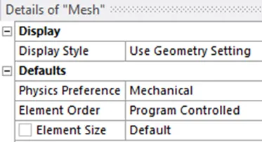
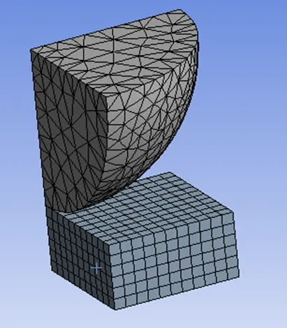
For the meshing part of default solver settings, the ANSYS solver will use the default or recommended mesh value for the model.
Boundary Conditions
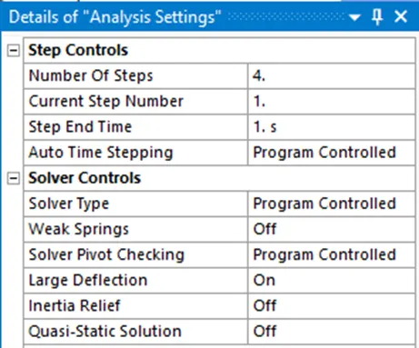
Analysis settings:
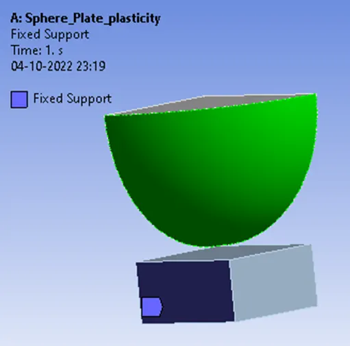
Fixed Support on Flat Plate
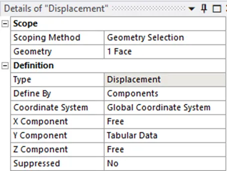
Displacement on Sphere
Simulation Results
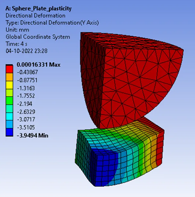
Directional Deformation
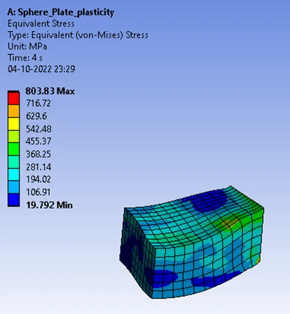
Equivalent Stress
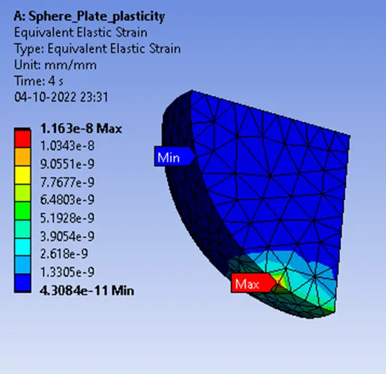
Equivalent Elastic strain
Concluding Result
What is Plastic Deformation?
It is the permanent distortion that occurs when a material is subjected to tensile, compressive, bending, or torsion stresses that exceed its yield strength and cause it to elongate, compress, buckle, bend or twist.
The opposite of elasticity is plasticity, when something is stretched and it stays stretched, the material is said to be plastic. When energy goes into changing the shape of some material and it stays changed, that is said to be plastic deformation. Mechanical energy is lost whenever an object undergoes plastic deformation.
Yield Strength The load after which the plastic behavior or permanent deformation starts in a material. In other words, the load above which the material cannot regain its original shape is called Yield Strength.
The equivalent stress of the Flat plate of material as Structural steel NL was calculated as 803.83 MPa which is higher than the material property tabulated yield strength as 250 MPa which clearly shows that plastic deformation has occurred when it cannot regain its original shape.