Week 2 Bevel Gear Challenge
Bevel Gear Challenge
Objective
Perform a grid dependency test for the Bevel gear simulation for mesh sizes of 6,5 and 4 mm and Solve for Von-Mises stress, Equivalent elastic strain, and Total Deformation using the previously mentioned mesh sizes.
What is the Grid Dependency Test? Explain its Uses.
When you are going to find a numerical solution through discretization of a governing differential equation in FEA (Finite Element Analysis) then your solution will be dependent upon a number of Mesh sizes or grid points (i.e. Nodes and Elements), generally, when you increase the number of Mesh size or grid points the solution will be more accurate but the main problem is that at what extend we have to increase this number of Mesh size or grid point so that when your solution does not change with the further changing of no. of grid points.
In Short: A grid-dependent solution is a solution that does not vary significantly even when you refine your mesh further so that an optimum mesh size is decided upon.
Explanatory:
When you start with a coarse mesh and solve, you may notice a difference in results as you make your mesh finer. But there exists a limit, beyond which you won't observe any changes in the results even after you make it finer. Then we may state that we have achieved grid dependence. At this point, the mesh will be fine enough to capture the most intricate details of the flow, which is why making it finer will not make any changes in the results.
Uses
For Solving Complex non-linear geometric shapes
Refining the mesh in the area of interest
Geometry is in focus for obtaining optimal near approximate or near-exact results.
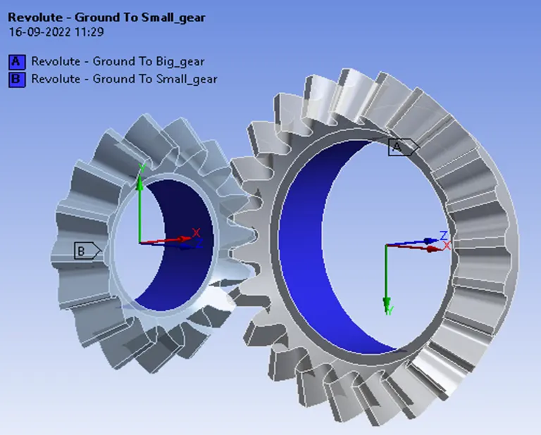
CAD Model of the Bevel Gear is incorporated for Analysis (Front view & Right view)
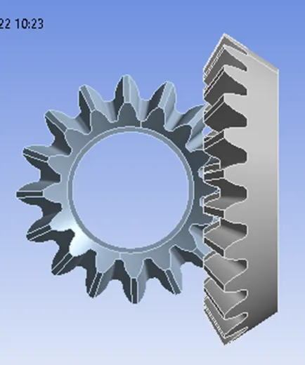
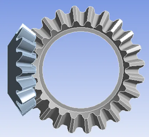
Test 1 Meshing @ 4mm & Face Sizing at 1.75mm
Material Used: Structural steel for all the 3 tests
Connections
Contact Settings:
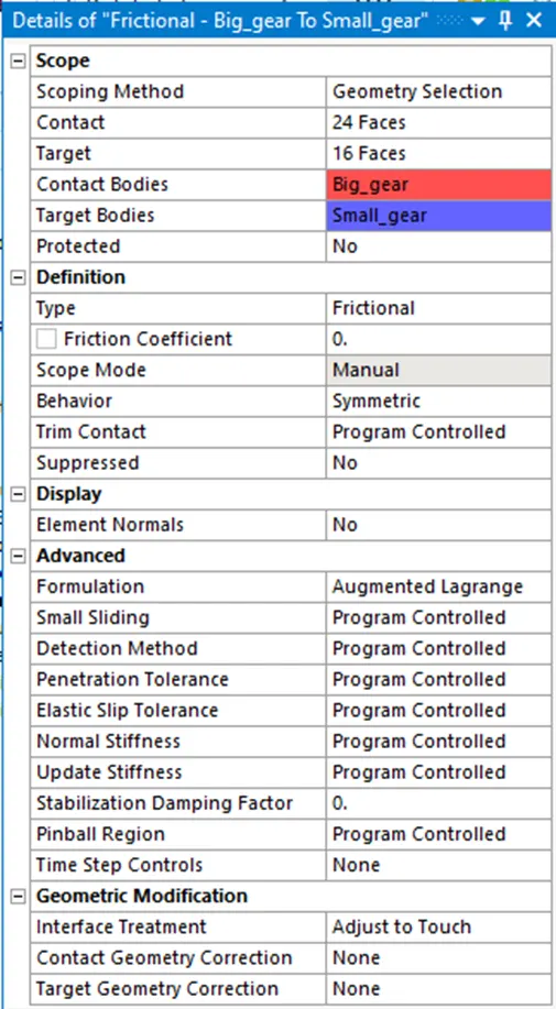
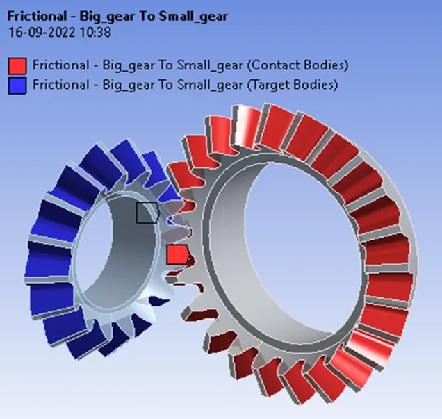
Initiating contact settings is crucial for the designer and end-user since the meshing of contact surfaces is discretionary of the designer as to what to ignore and which to consider. Here the bevel gears tooth is in constant contact to undergo dynamic attributes of stresses, strains, and deformations as such the designer have to closely observe and predict the cognitive analytical ability to consider it as crucial for setting the contact region and ignoring other factors for efficient (i.e. Saving Time and Energy) Way of Analysing.
Likewise, as mentioned above considering ourselves as an FEA analyst we opt for Bevel gears tooth areas as a reliable area for setting the contact parameters such as Type Definition- Frictional, Behaviour-Symmetric, Formulation- Augmented Lagrange, Interface Treatment-Adjust to Touch and ignore the rest. For the other two tests of 5mm and 6mm, meshing the same parameters of contact settings are followed.
Joint Settings
Joints Set as (Revolute)
Why do we set joints as Revolute because we are using gears. As a result of it, we have to define an axis of rotation in which it rotates. Revolute joint with Body to ground contact is chosen here. For the other two tests of 5mm and 6mm, meshing the same parameters of Joint settings are followed.
Meshing
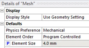
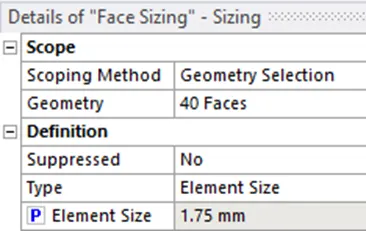
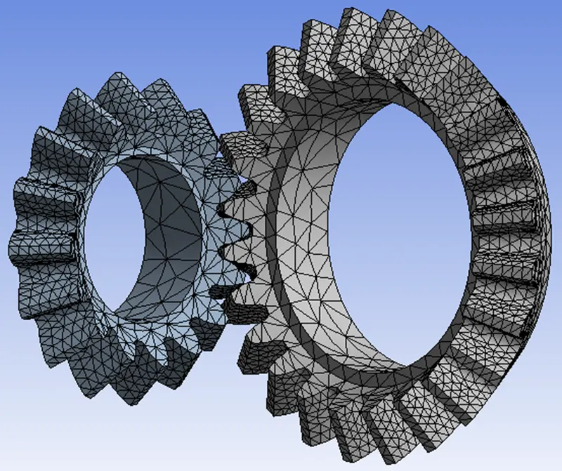
Choosing the Mesh size for our Entire model as 4mm including the Face sizing of 1.75mm at both the gear tooth faces for our analysis is shown below.
Boundary Conditions
Analysis settings:
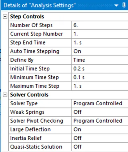
The Time Step controls of Analysis settings are crucial for Convergence of Force and Criterion values /curves as this helps the solver converge without any issues.
If we take a smaller time step the solver finds it easy to start with the initial calculation and slowly increases to its maximum time step which helps the solver converge faster without any issues. So always keep this in mind case you are experiencing any convergence issues try to reduce the time step values and start with a less value so that it helps the solver converge faster. For the other two tests of 5mm and 6mm, meshing the same parameters of Analysis settings are followed.
Joint Load Setup
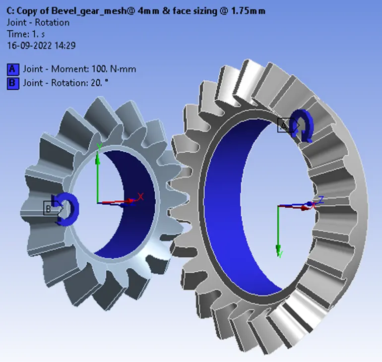
Joint – Moment For Big _Gear and Joint- Rotation for Small_Gear
The small gear is given an anti-clockwise rotation with 20° increment, up to 120° while the Big gear is given a Moment in a Clockwise direction with 100Nm for each step as shown below. For the other two tests of 5mm and 6mm meshing same parameters of Joint Load Setup settings are followed.
Simulation Results
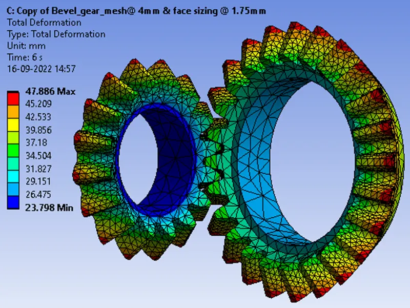
Total Deformation
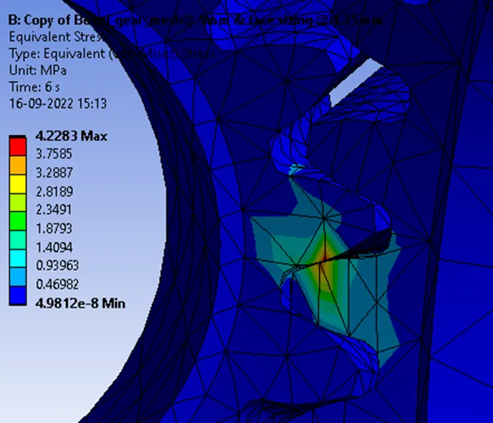
Equivalent von-mises stress
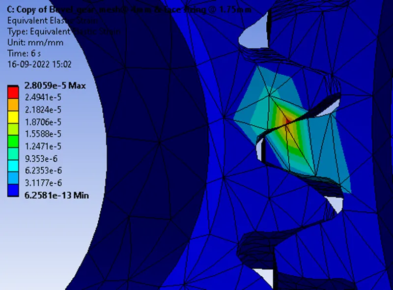
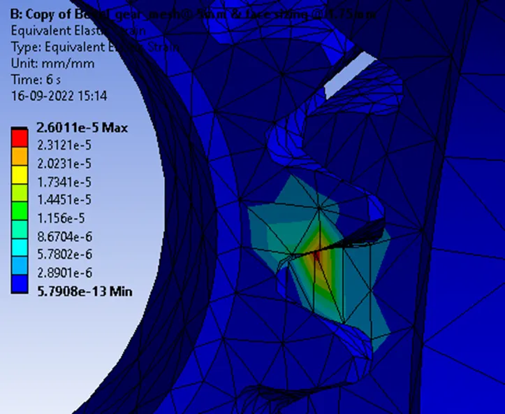
Equivalent elastic strain
Test 2 Meshing @ 5mm & Face Sizing at 1.75mm
Simulation Results
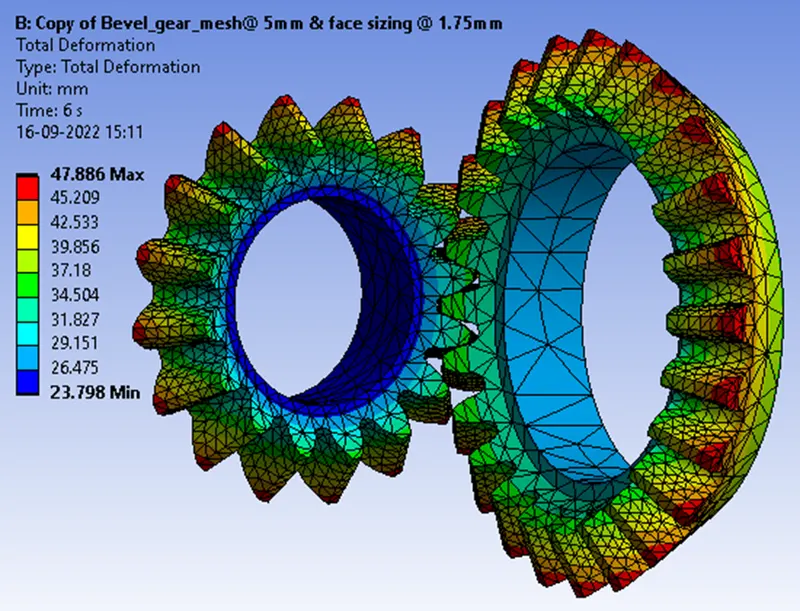
Total Deformation
Equivalent von-mises stress
Equivalent elastic strain
Test 3 Meshing @ 6mm & Face Sizing at 1.75mm
Simulation Results
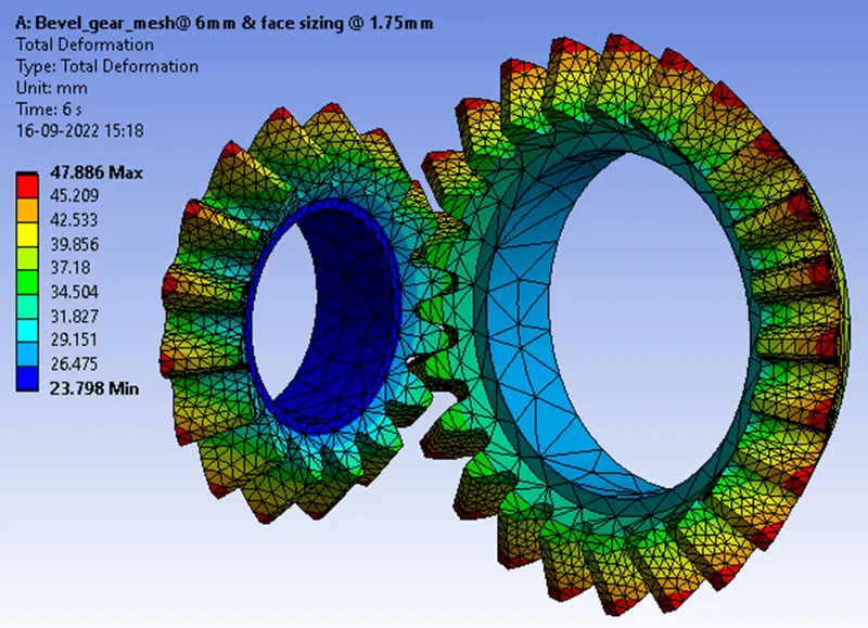
Total Deformation
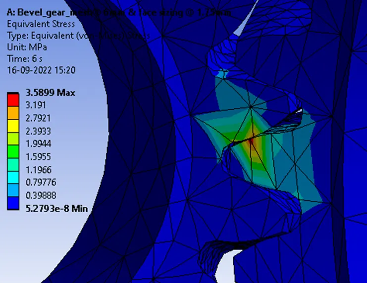
Equivalent von-mises Stress
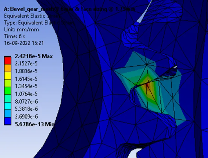
Equivalent elastic Strain
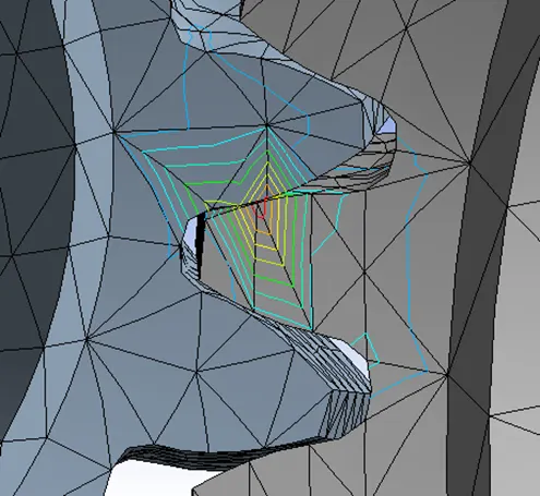
Possible Location for Fracture and Failure.
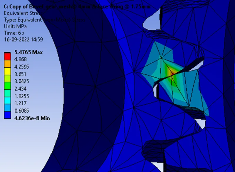
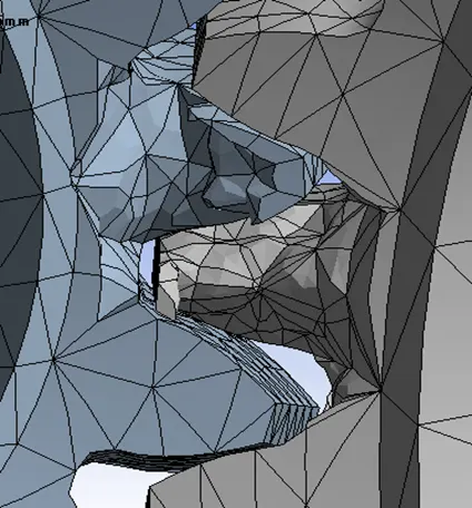
The lines surrounding the maximum stresses represent the gear tooth’s going to wear in the future due to tensile and contact stresses and the adjacent result shows how it will wear gradually.
Conclusion.
|
Analyzing Cases for |
Meshing at |
Total Deformation (mm) |
Von-mises stress [MPa] |
Elastic strain (mm) |
|
Test 1 |
4mm |
47.886 Max |
5.4765 Max |
2.8059e^-5 Max |
|
Test 2 |
5mm |
47.886 Max |
4.2283 Max |
2.6011e^-5 Max |
|
Test 3 |
6mm |
47.886 Max |
3.5899 Max |
2.4218e^-5 Max |
|
Meshing at |
Nodes |
Elements |
|
4mm |
24122 |
12950 |
|
5mm |
24038 |
12915 |
|
6mm |
23545 |
12655 |
After analyzing our simulation, we tabulated the necessary results to determine the grid dependency test factors for our objective. Looking at Total deformation results it is constant in all tests and for von-mises stress, it varies according to the mesh size for Elastic strain it is constant with the minute difference that clearly shows the fact that the optimal grid dependency test has been successfully achieved.
How?
Let us relate our calculations with Total deformation v/s Elastic strain as our solution for a Bevel gear problem, if… for 4mm Mesh size or grid points, 5mm Mesh size or grid points, and 6mm Mesh size or grid points the solution (say in form of graph b/w Total deformation vs Elastic strain) are same it means for 4mm or 5mm or 6mm Mesh size or grid point we can use any one of 4mm/5mm/6mm as optimum (most favorable) for the solution and solutions is not going to change for further increase or decrease in no. of Mesh size or grid points and it might be possible that the accuracy can be decreased also when you will further increase the no of Mesh size or grid points.
So in our case, we take 5mm as the optimum Mesh size or grid points for your solution and it is called the grid independence or grid dependence test.