Solid meshing
AIM:
For the given Rearview mirror component, check for the geometrical errors and mesh the Surfaces with the given 2D element Quality criteria are given below.
|
S.No |
Quality Criteria |
Value |
|
1 |
Target/Average length |
1 |
|
2 |
Minimum Length |
0.5 |
|
3 |
Maximum Length |
2 |
Use tetra elements to mesh the Volumes defined in the model and check for the below quality after Volume meshing.
|
S.No |
Quality Criteria |
Value |
|
1 |
Tet collapse |
0.2 |
To Write a detailed report on your approach for this model.
PROCEDURE:
The model to be worked on is shown below.
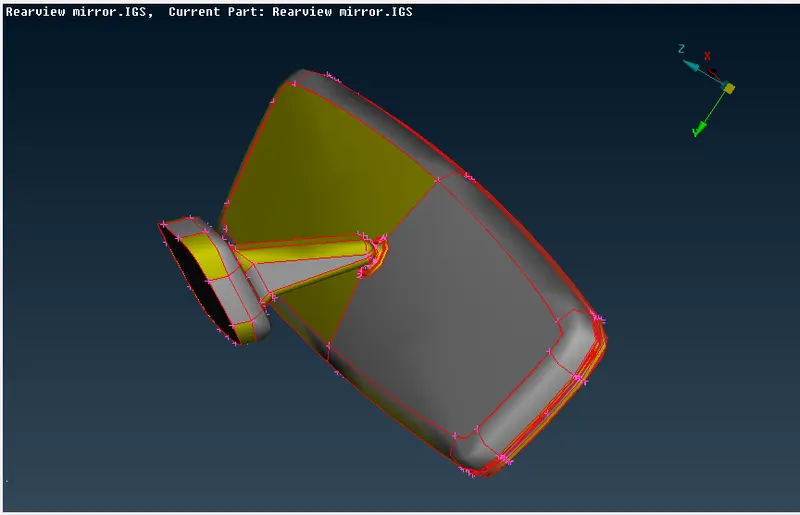
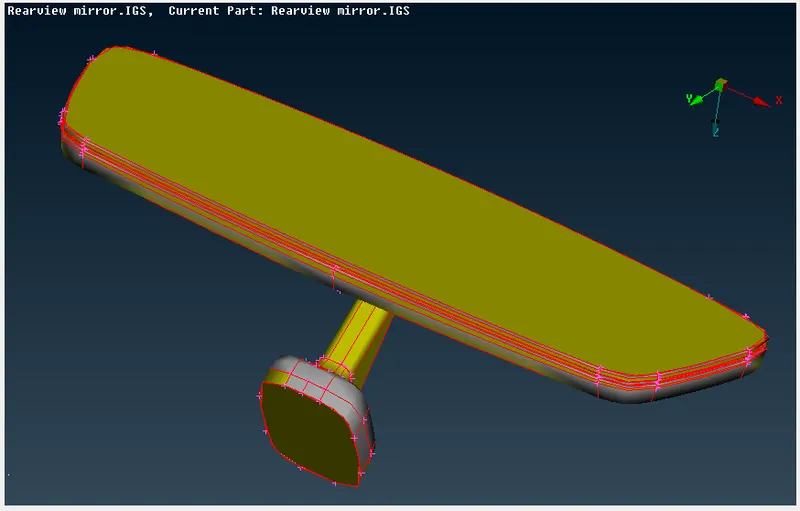
The model is solid and we need to use the volume module to mesh the surface. There are 2 types of meshing, tetra mesh, and Hexa mesh. We will be doing a tetra mesh on the model using the steps explained below.
1. To perform geometry check and geometry clean-up
We first go to Tools->Checks->Geometry. We run a geometry check on the model and the result is shown below.
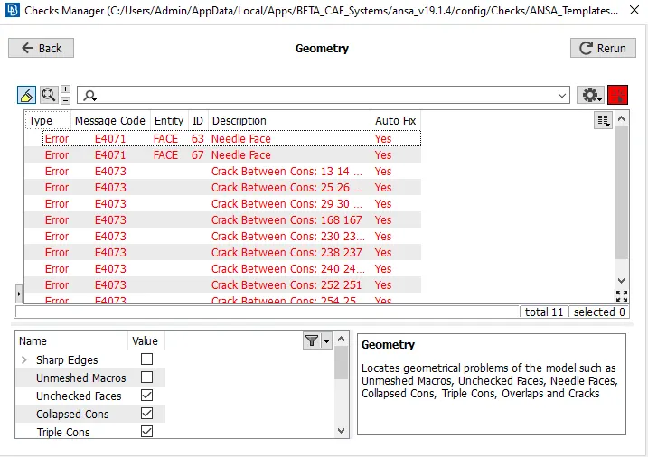
The above-mentioned errors should be fixed, we can use the auto-fix feature and re-run the geometry checkup.
To fix the single CONS, we got to Topo module->Faces->TOPO. After this, we orient the surfaces to make sure all of them are on the same plane, we do this by going to the Topo module->Faces->Orient. We re-run the geometry module and auto-fix the existing errors.
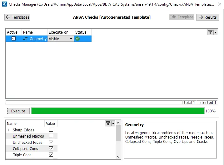
Now, we need to clean up the geometry by removing unnecessary hot points and cuts.
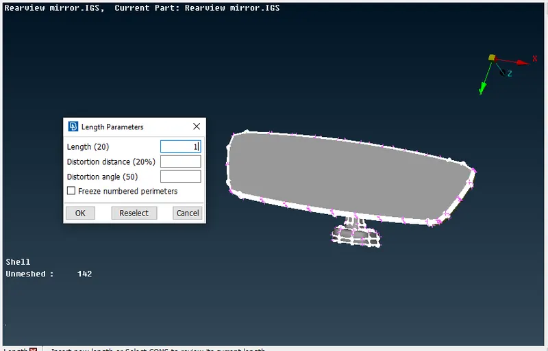
We first set the perimeter and macro length to observe the accuracy of the design. We go to Mesh module-> Perimeters->Length. We set the perimeter and macro length to 1 as shown in the figure below.
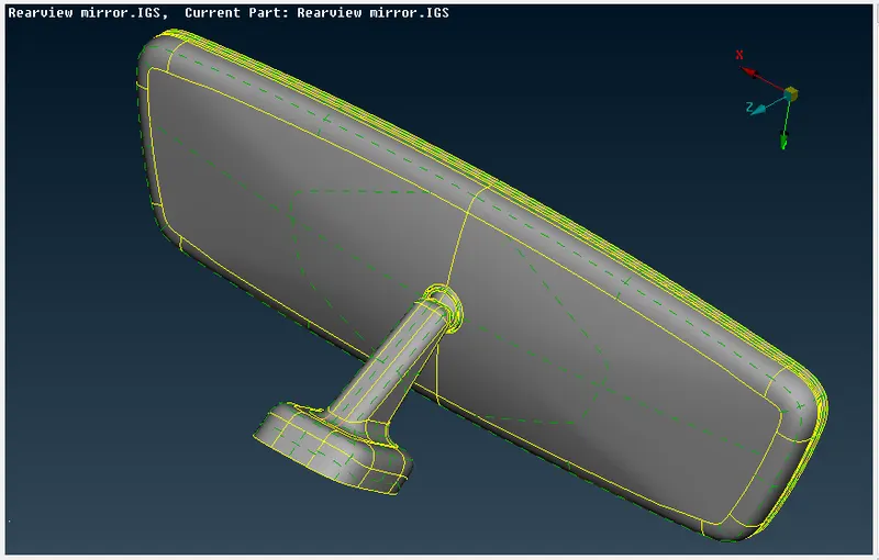
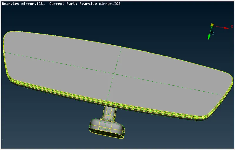
The model after geometry cleanup and checks will be as shown below.
2. Mesh parameters and Quality Criteria
As this is a solid component, we don't take out its mid-surface. We mesh the outer surface of the component directly and then extrude it to the rest of its volume. Before we start meshing, we need to set the mesh parameters and quality criteria as shown below.
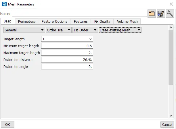
The type of mesh can be changed to ortho trias and normal trias depending on the surface that is being meshed.
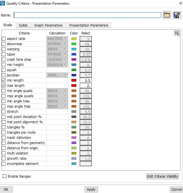
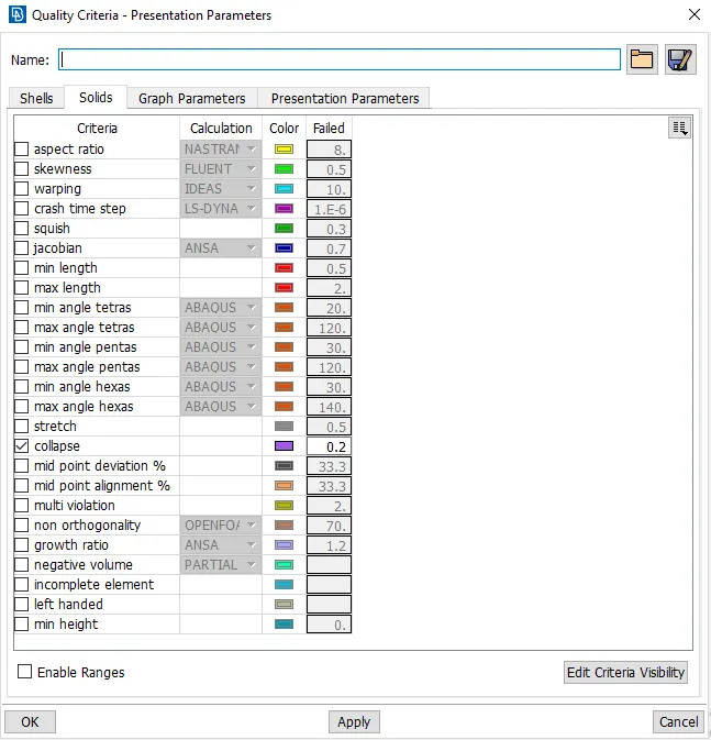
We set the minimum and maximum length in the shells and tetra collapse in the solids section of the quality criteria as shown below.
3. To generate a surface mesh with TRIA elements
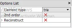
We mesh the outer surface of the model as it is a solid component. We go to Mesh module->Mesh Generation->Spot mesh. In the spot mesh, we can choose between tria and ortho tria types of meshing. Ortho-tria is used on curved surfaces and normal trias are used on flat surfaces.
The below image shows the choice of meshing to be done.
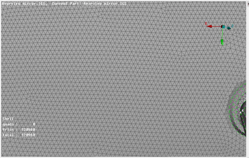
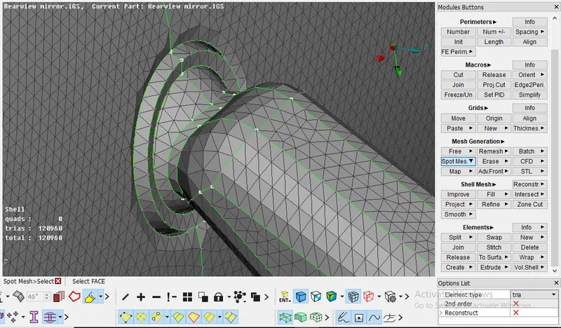
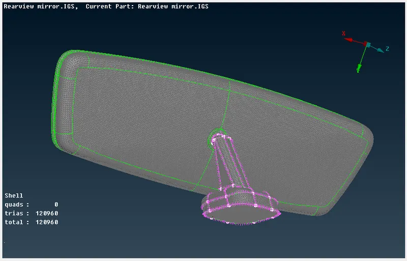
We mesh the component accordingly, the mesh will consist of ortho-trias and normal trias as shown in the below images.
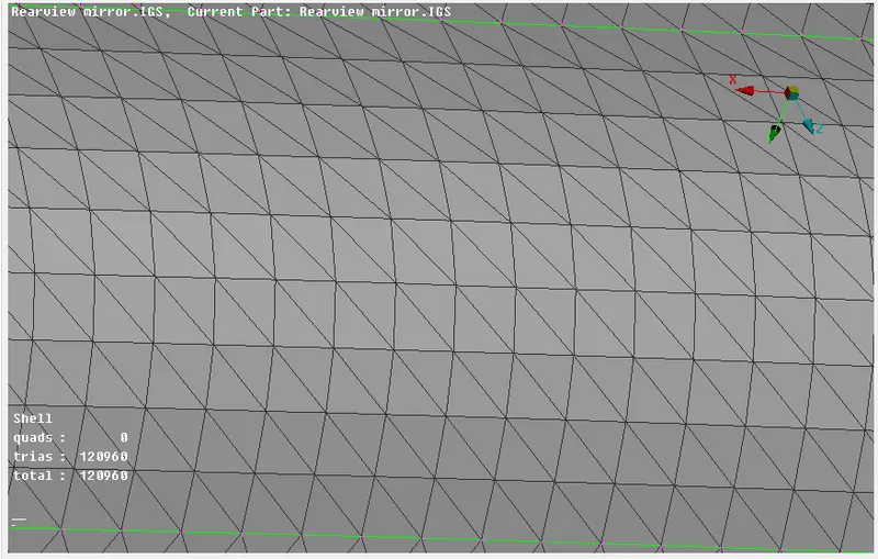
The above image shows ortho-trias, we can see the uniform arrangement of the trias on the surface.
The above image shows the normal trias which are non-uniform throughout the surface.
The above image shows us the mixture of ortho-trias and normal trias in the component.
The entire surface of the component is meshed with a mixture of ortho-trias and normal trias as shown in the above image.
4. To solve all the 'OFF' elements for the meshed surface.
We can see that there are a total of 24 'OFF' elements on the surface mesh all failing for minimum length criteria as shown below.
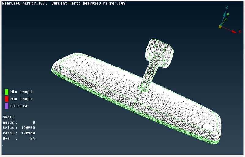
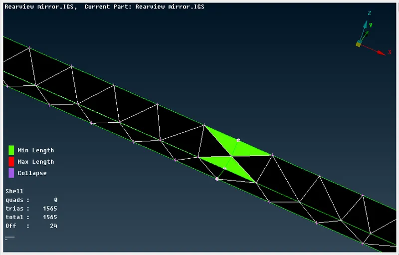
We can fix it by reconstructing the mesh or rearranging the hot points. Here, we can use the reconstruction tool.
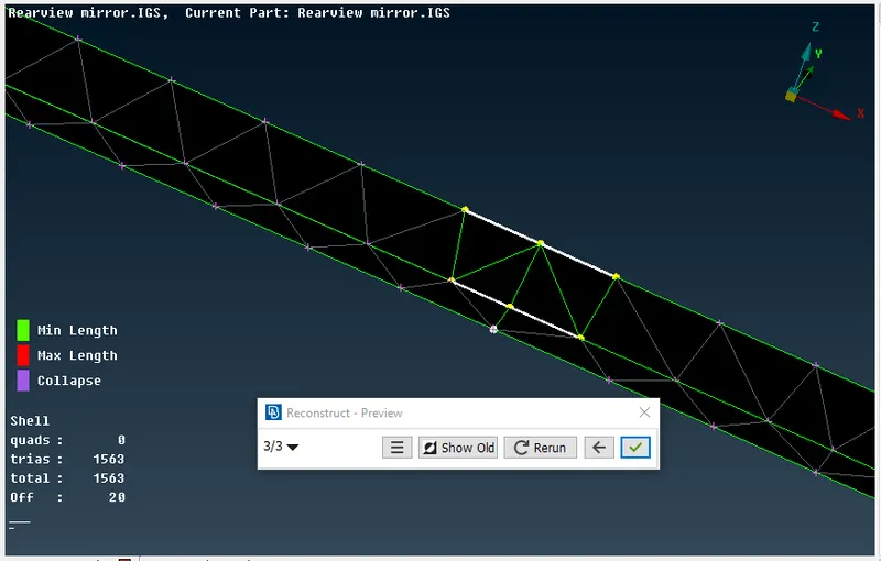
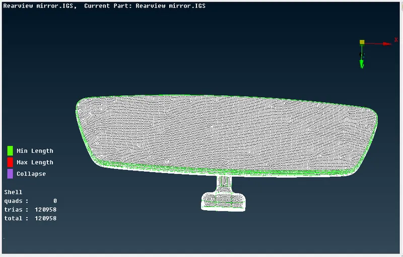
We follow this procedure at all the 'OFF' elements and resolve it. The solved component with zero failures in the surface mesh is shown below.
5. To define a Volume in volume mesh deck
Now we need to create a mesh throughout the volume of the component. We go to the volume mesh module to create and define a volume and then mesh it throughout.
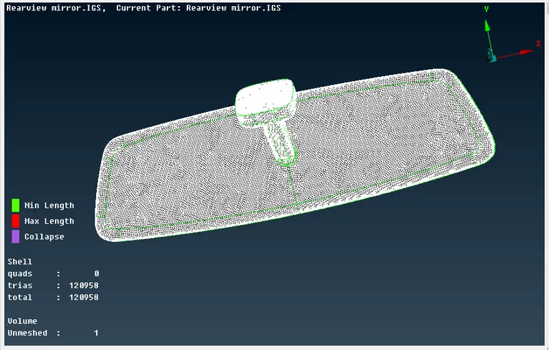
We can see from the above that the volume is shown as unmeshed. So we now first define the volume as shown below.
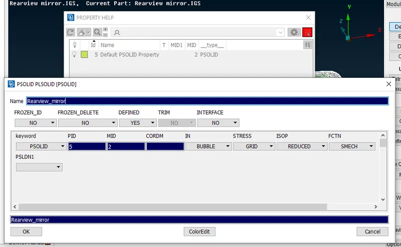
We create a 'PSOLID' property ID for the volume as shown above and start to define the volumes for the component.
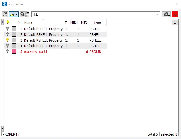
The property ID 'rearview_part1' that is created is shown in the above image.
To prevent the intersection failure during meshing, we divide the components and assign volumes separately for each of them.
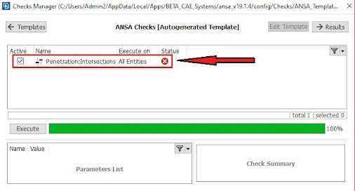
The intersection error is shown in the above image.
The four components of this rearview mirror model are shown below and each of these has its own property ID.
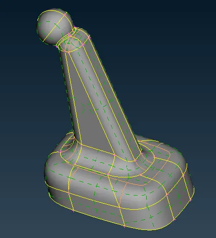
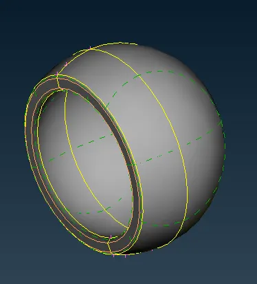
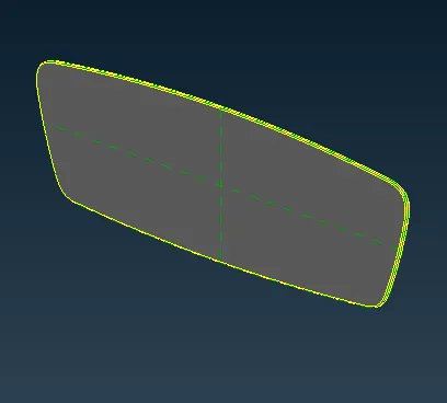
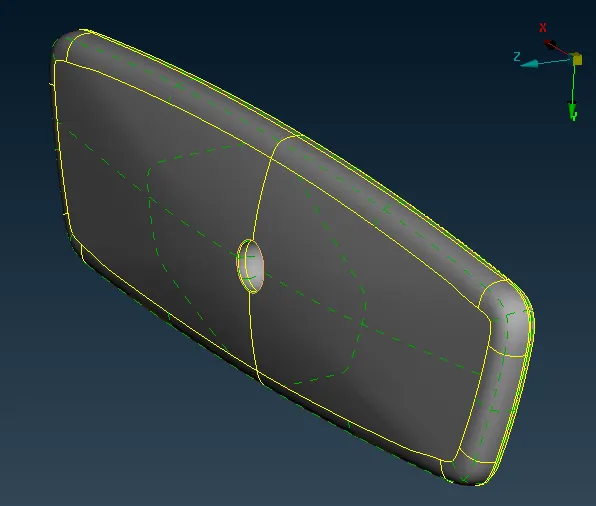
Now we define the volumes for each of these components by going to Volume module->Volumes->Define->select the faces and confirm the selection. This can be verified by going to Volumes->List and the list will contain all the defined volumes for the part.
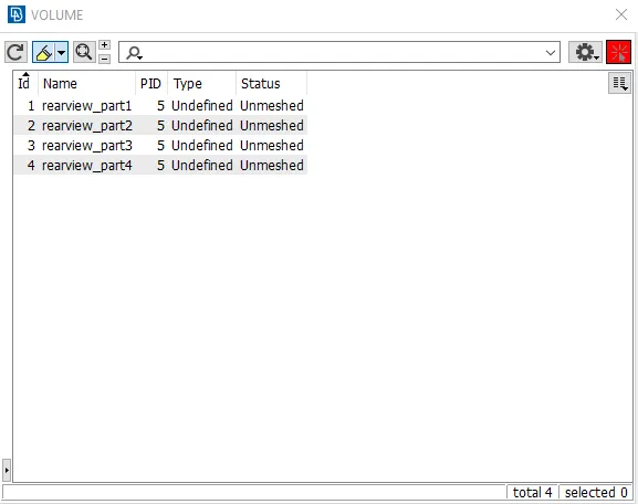
The above list shows us the type of mesh and the status of the mesh for each volume.
6. To mesh the volumes with either Tetra Rapid or Tetra FEM algorithm.
With this, we can now proceed to mesh the components one by one.
We open the component which will be meshed. We go to the list and right-click on the volume, we find the re-mesh option and click on it.
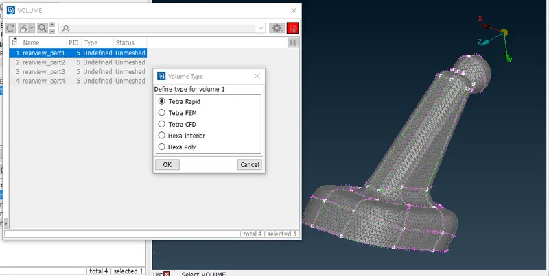
As shown in the below image, a new window is opened where we can choose the type of mesh. We go with Tetra Rapid for this model and confirm with the scroll button.
The meshed component is shown below.
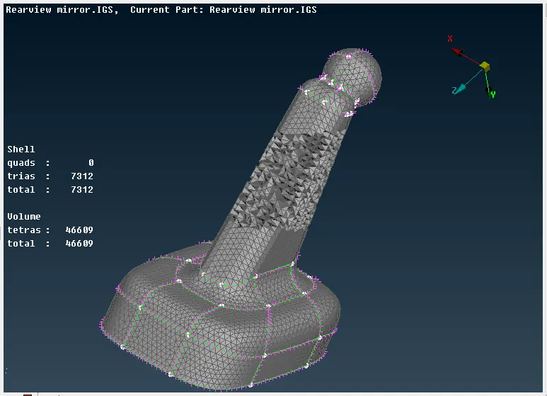
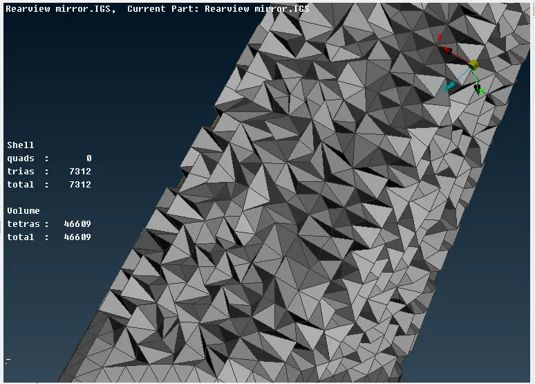
There are a total of 46609 tetras in the component and the close-up look is shown in the below image.
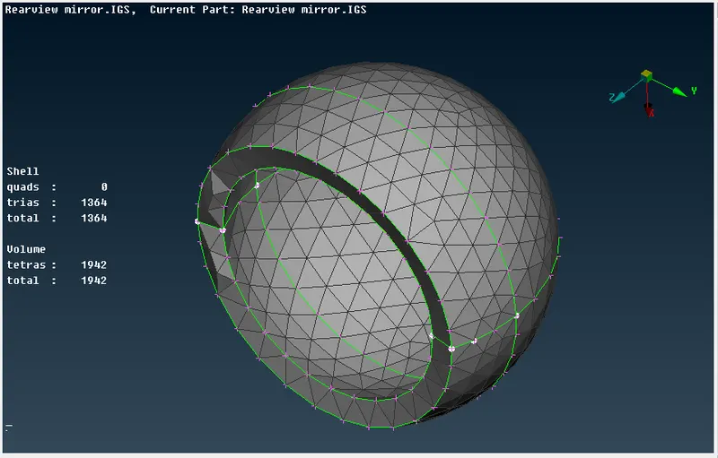
The volume mesh of the second component is shown below.
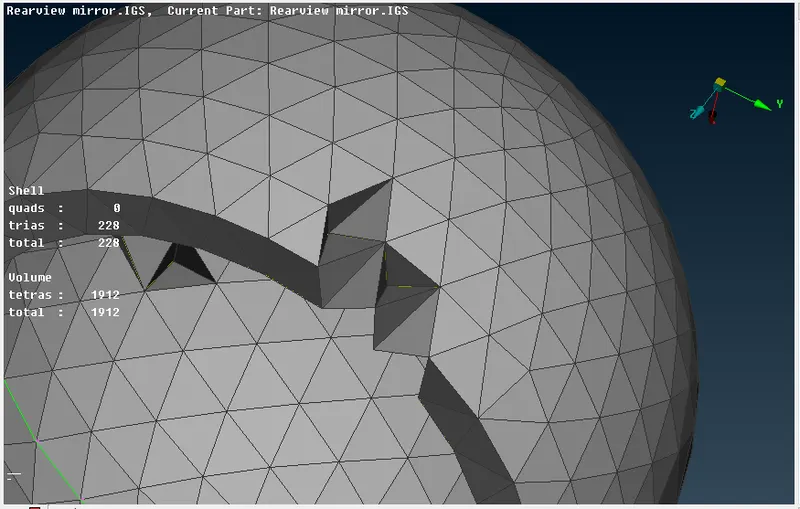
The volume mesh of the third component is shown below.
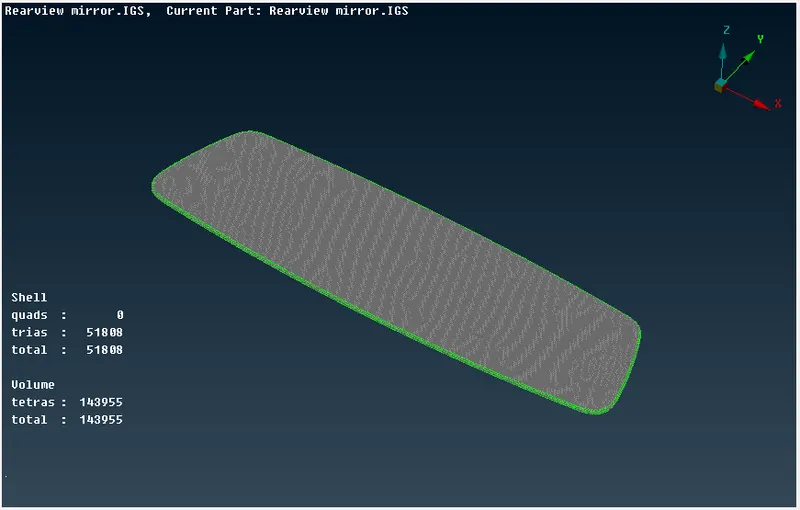
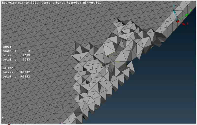
The volume mesh of the fourth component is shown below.
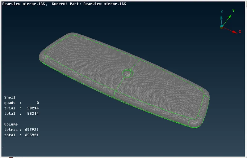
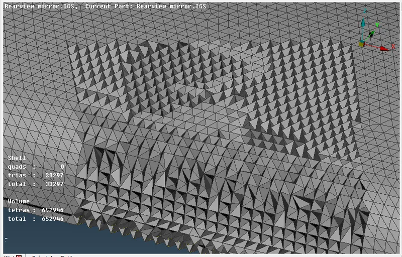
7. To solve all the 'OFF' elements for volume meshed components with given quality criteria.
Now, we need to check if the quality criteria for the tetra mesh are satisfied or not. The quality criteria are the tet collapse and the value set is 0.2.
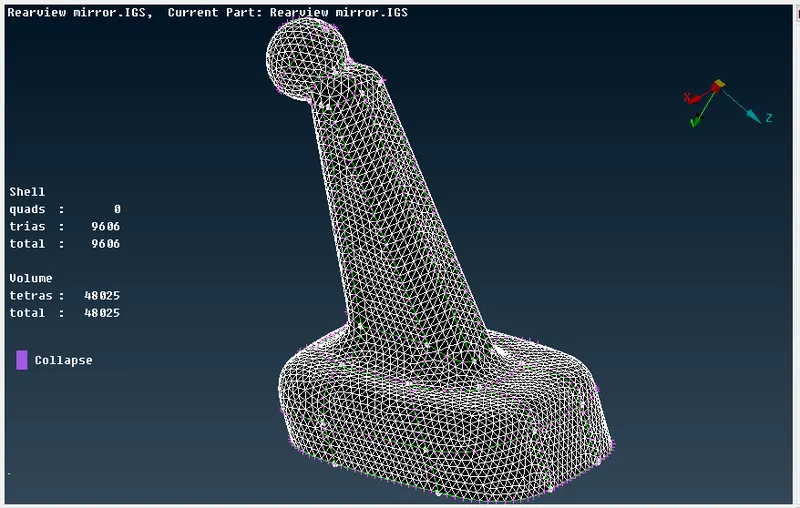
We can see from the above image, the tet collapse has not failed in the component. We follow the same procedure for the other components.
Similarly, the quality criteria for the volume mesh of the second component are satisfied as shown in the below image.
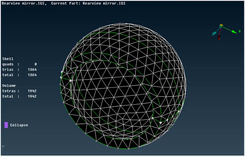
The quality criteria for the volume mesh of the third component are satisfied as shown in the below image.
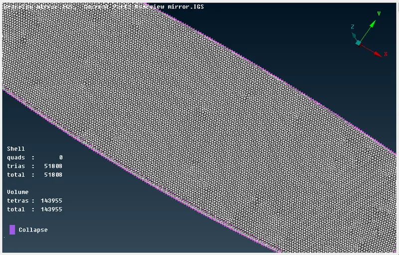
The quality criteria for the volume mesh of the fourth component are satisfied as shown in the below image.
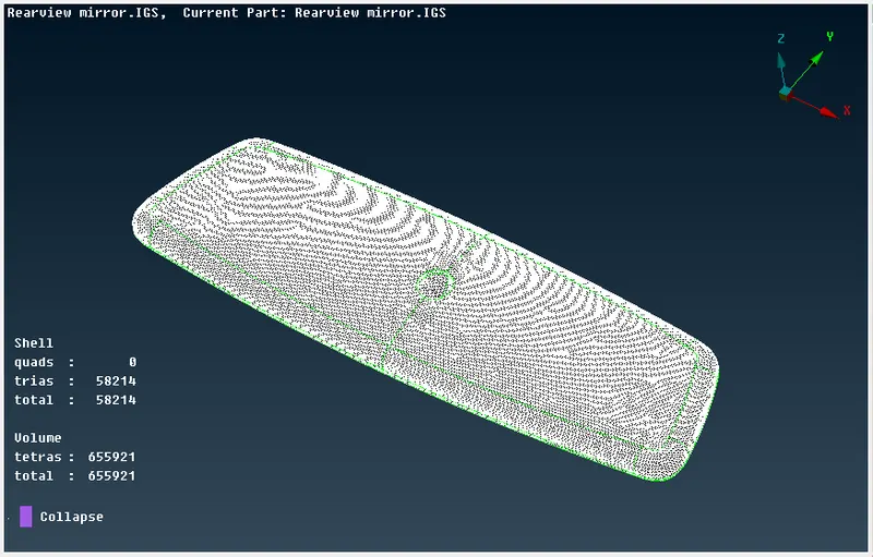
With this, we have completed meshing the surface and the volume of the model. The final outcome is shown below.
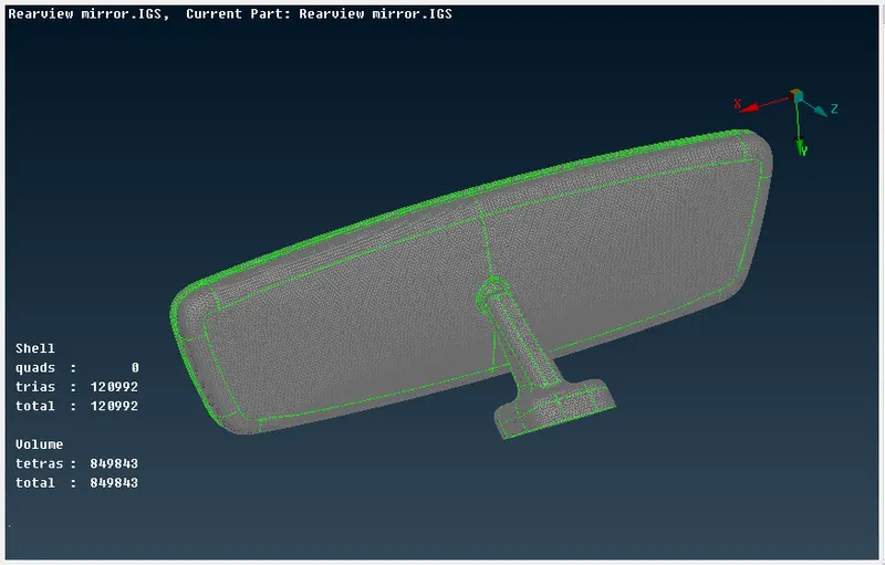
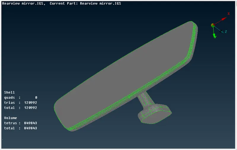
The shell has a total of 120992 trias and the solid has a total of 849843 tetras and it satisfies all the mesh parameters and the quality criteria.
CONCLUSION -
The geometry cleanup and the checks were conducted on the model, the surface mesh is created according to the mesh parameters and the quality criteria is satisfied. The volume mesh is also created and all the errors and kinks are solved and the model satisfies the quality criteria.
The link for the model is given below.