Week- 5 - Solid meshing
CHALLENGE: SOLID MESHING
AIM:
To perform tetra meshing for a Rear-view mirror with the quality criteria given.
OBJECTIVE:
- Understand about 3D tetra meshing generation.
- To study about different methods of tetra meshing and 3D mesh quality checking.
- To learn about 3D meshing from 2D elements.
THEORY:
3D elements are usually used to mesh volumes. They are derived from 2D elements that are used when the problem is unable to be simplified. 3D solid elements only account for translational displacements.
These elements are suitable for three-dimensional analysis. uses for solid parts and sheets of thickness more than 5mm, Transmission castings. engine blocks etc.
Tetra element is the 4 noded with 4 triangle faces are formulated in three-dimensional space with three degrees of freedom per node. These are the translational degrees of freedom in the X, Y and Z directions, respectively. In the figure Tetra element is shown for 4 nodes.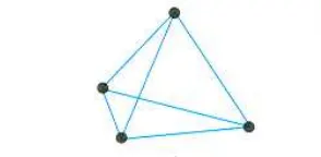
3D elements are converted from 2D elements, which are used when the model has more than 6mm thickness.
Tetra Collapse: Ideal Value = 1.0
Tetra collapse = h*1.24/A (Defined as distance of node from opposite face divided by area of the face multiplied by 1.24)
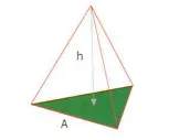
Note: Tet collapse values less than 0.15 or 0.2 are not acceptable.
GIVEN CRITERIA:
2D element Quality criteria given below,
|
S.No |
Quality Criteria |
Value |
|
1 |
Target/Average length |
1 |
|
2 |
Minimum Length |
0.5 |
|
3 |
Maximum Length |
2 |
For 3D element,
|
S.No |
Quality Criteria |
Value |
|
1 |
Tet collapse |
0.2 |
PROCEDURE:
Step 1: Importing Geometry
- The initial step is to import the geometry into ANSA.
File → open → select the file → open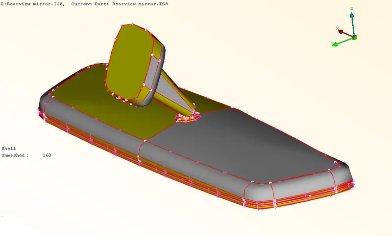
Figure-1: Imported model - Check the imported geometry for single cons, double cons, triple cons, connection etc. In Topo module, the single cons will be in red, double con will be yellow and triple con will be blue. But in mesh module, the only difference is in the double con color(Green color).
- There are four parts in the imported model. We approach them separately with same procedure.
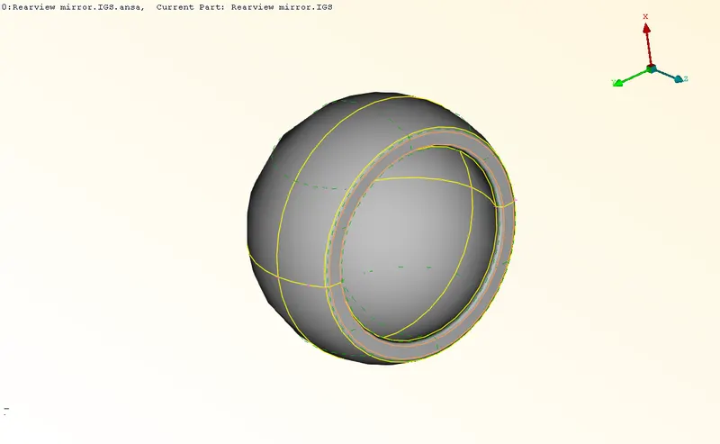
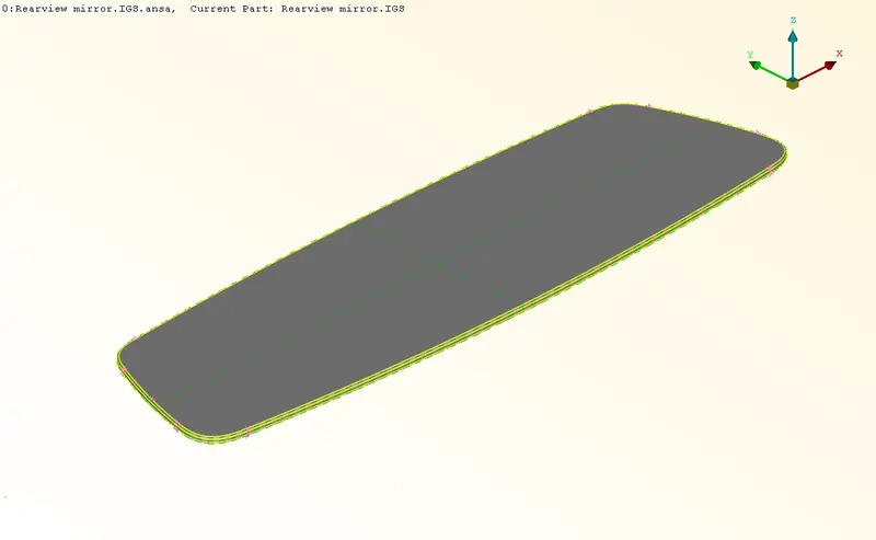
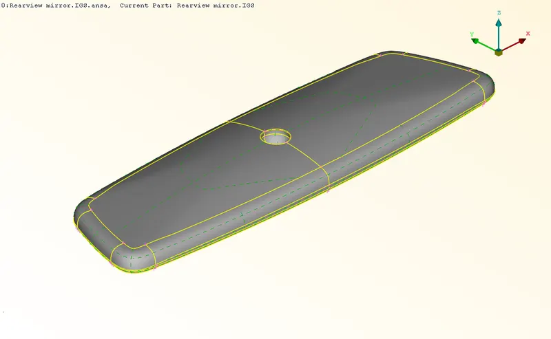
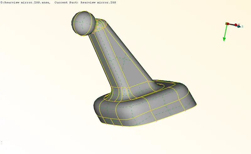
Figure-2: Different parts of Rear-view mirror
Step -2: Geometry cleanup
- Cons resolution: We have to do the cons resolution to check the actual shape of the cones in the geometry. There are two tools for that. One is 'Fine' option in the Topo module under Auxilaries. The other one is 'Length' tool from Mesh module under Perimeters. The 'Length' tool will help to done this in a single step when compared with fine tool.
Mesh module → Perimeters → Length → Perimeter/macros (do this for both) → select the whole surface → middle mouse click → gave the value as 1 → apply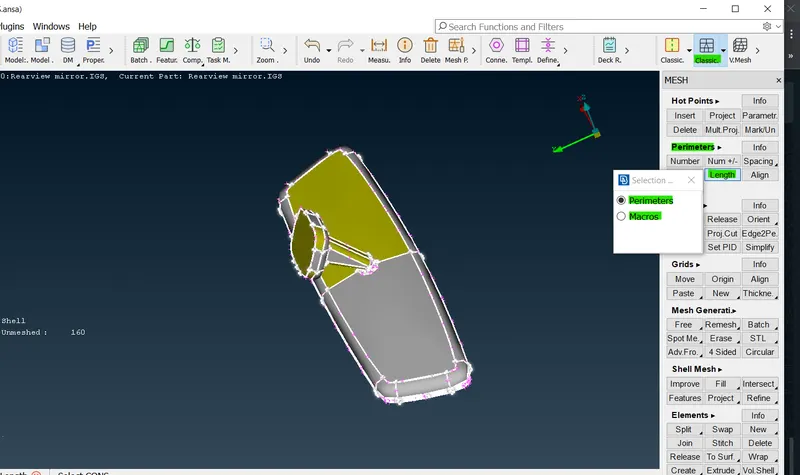
Figure-3: Cons resolution - Connectivity correction: There are surfaces without connection in the imported model (Single cons). We have to correct it before doing meshing. We could use 'Topo' tool to perform topology.
Topo module → Faces → Topo → select the whole surface at once → Apply (Middle mouse click).
After performing Topo, we could see that all the single cons are converted into double cons(Yellow).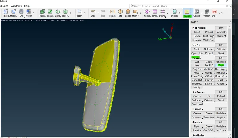
Figure-4: Using 'Topo' - Orientation correction: As we could observe that the given surface is with mixed yellow and grey color. This shows mixed normal direction in the surface. So, we have to correct it as either yellow or grey in outer surface. The tool, 'Orient' is used for this purpose.
Topo module → Faces → Orient → Choose select, Visible and Auto appropriately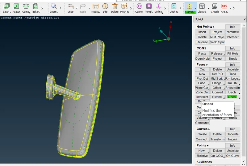
Figure-5: Face orientation correcting - Geometry check: We need to check the geometry by using 'geometry' tool to find and correct any other errors in the imported geometry.
Tool tab → Check → Geometry → Tick the single cone as well → Execute → If any errors pop up in red color select them at once → right mouse click → Fix → If not fixed, try manually → Then execute the geometry check again, it will show No errors or warning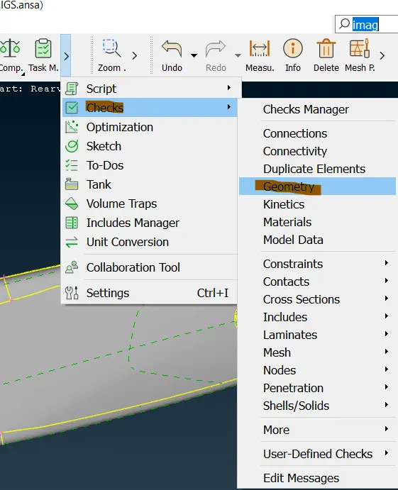
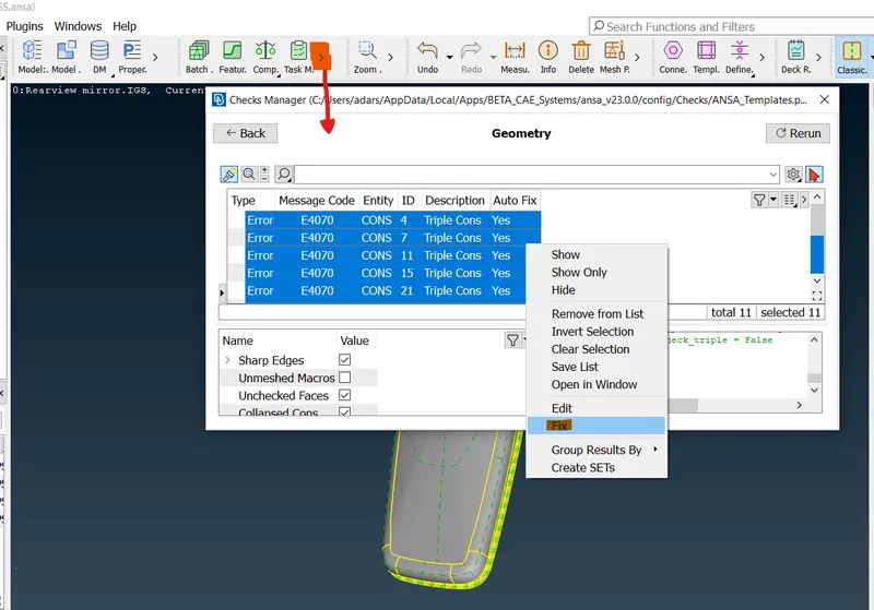
Figure-6: Geometry check
Step-3: Generating 2D mesh
- Here, we approach each part separately in the same manner/ procedure. First, switch show only one part.
- Cons resolution: We have to give the perimeter and macros from Length tool as target element size.
Mesh module → Perimeters → Length → Perimeter/macros → select the whole surface → middle mouse click → gave the value as target element size (It is 1) → apply (Note: Do the same for macros option in Length tool as well)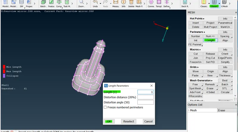
Figure-6: Cons resolution - Setting up the quality Criteria and mesh parameter: We have to set the quality criteria as well as mesh parameter as specified.
Utilities tab → Mesh Parameter → Set Element type: tria , target element size, minimum element size → Ok
Utilities tab → Quality Criteria → From Shell tab set 2D element qualities and from Solid tab set 3D element quality(Tet collapse) → Ok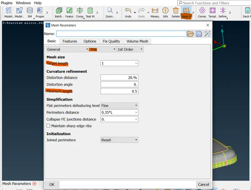
Figure-7: Mesh Parameter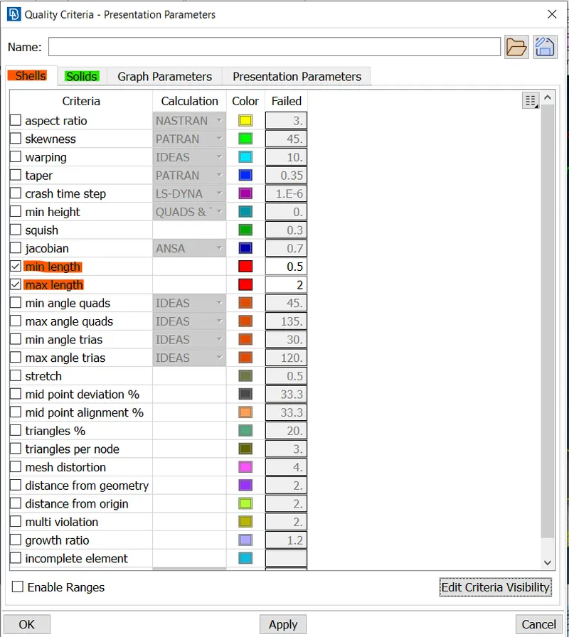
Figure-8: Quality Criteria - Avoiding places of element failure: There are near construction/ feature lines in the model. It may lead to element failure in quality. So, we need to suppress those line using 'cut' tool (Right click).
Use the 'Measure' tool from utilities to find out the distance between two construction/feature line. If the distance found is less than the minimum element length ( Here 0.5 units), suppress any one construction line.
Topo module → Faces → Cut or
Mesh module → Macros → Cut (Right click for suppressing)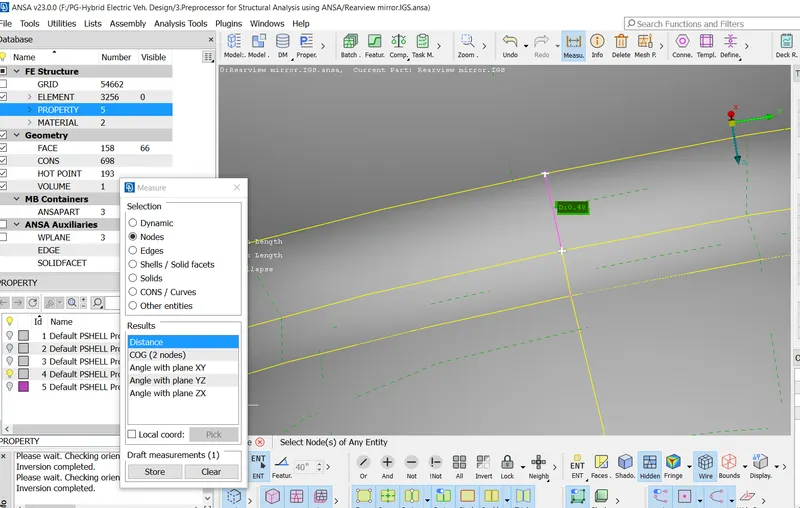
Figure-9: Measure tool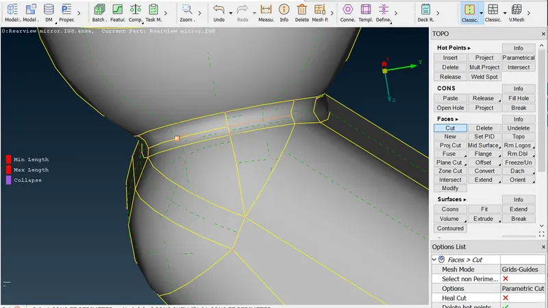
Figure-10: Suppressing construction/ feature lines - 2D meshing: We mesh with tria on flat regions and ortho tria on curved region. We mesh each part separately.
Select 'Best' option from Mesh generation tab in the mesh module. First, select the flat areas. Choose the tria option from option list. Then apply (Middle mouse click).
Mesh module → Mesh Generation → Best → Select surfaces, in option list change tria and ortho tria for flat and curved surfaces → Apply (Middle mouse click)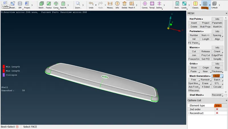
Figure-11: 2D meshing on flat surface
After meshing on flat surfaces, double click on the 'unmeshed' (or right click → show)- this will show the unmeshed curved surfaces. Then again select the 'Best' option from Mesh generation and select the 'ortho tria' from option list.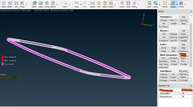
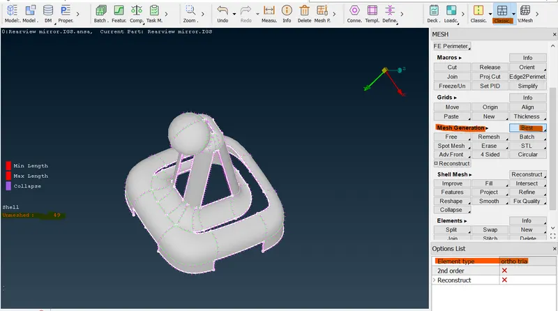
Figure-12: 2D meshing on unmeshed curved surfaces
Then click on the 'Neighbour All' to view the whole part. - Quality Correction: Click on the "Hidden' option which will shows failing element (off elements), unmeshed surfaces etc.
We can use reconstruct, smooth, improve options on failing elements to correct it.
Mesh module → Shell mesh → Reconstruct/ Improve/ Smooth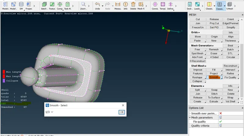
Figure-13: Using smooth tool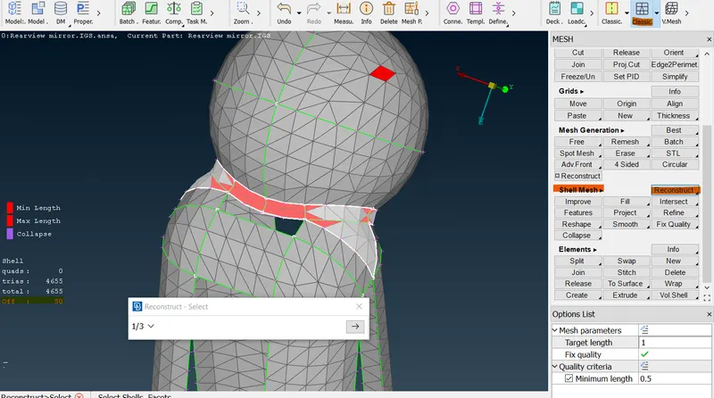
Figure-14: Using Reconstruct tool
Step-3: Pre volume check
- Here we checked for unmeshed area. The 'Hidden' tool will show, whether there are any unmeshed surfaces or not. If there, mesh those areas.
- We also check for single con, double con and triple con in the model. But, we initially correct it using Topo and Geometry tool. We can use Check → Geometry option for checking this as well.
- Penetration and Intersection Check: We check for intersection and penetration on the 2D element. If any error found, we have to correct it.
Tools → Checks → Penetration → Intersection → Execute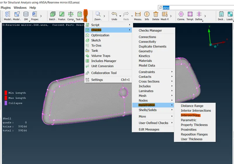
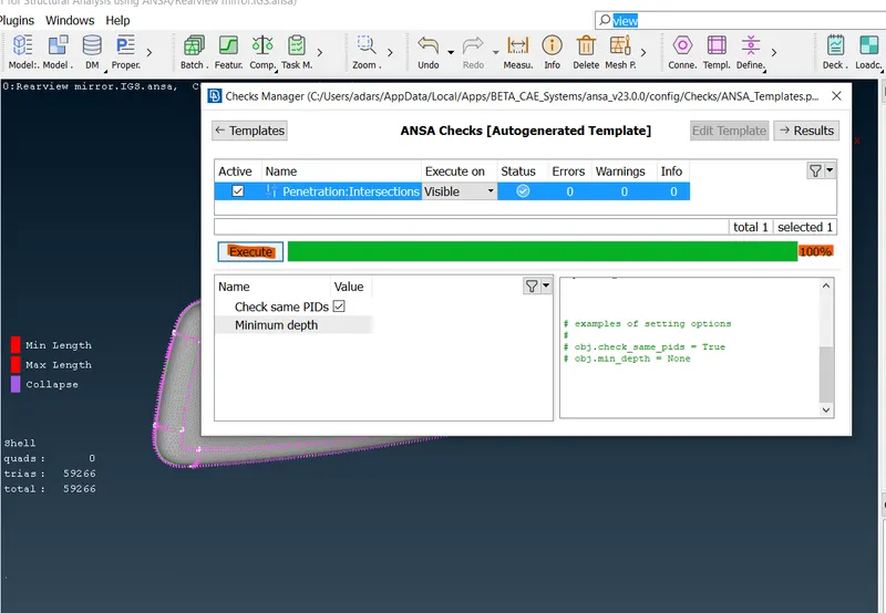
Figure-15: Penetration tool
Step-4: Volume Definition
- Before converting 2D to 3D elements we need to define the volume for creating 3D elements in them.
Volume mesh module → Volume → Define → Select Detect on: Visible → Ok
The above step will create the volume for visible geometry .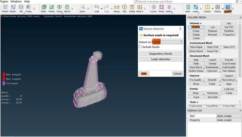
Figure-16: Volume definition
Step-5: Generating the 3D mesh
- After volume definition, we generate the 3D tetra mesh in the volume using 'Tetra Rapid' tool.
Volume mesh module → Unstructured Mesh → Tetra Rapid → Volume → Click on the surface → Apply (Middle mouse click)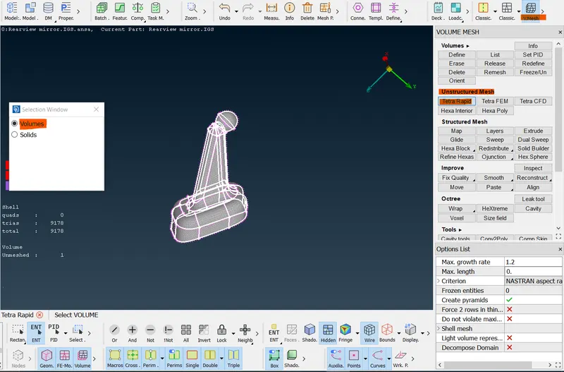
Figure-17: 3D tetra meshing - After creating the 3D tetra mesh, we have to check for elements which are failing tet collapse. The ' Hidden' tool will shows the failing elements. If any elements fail the criteria, correct it.
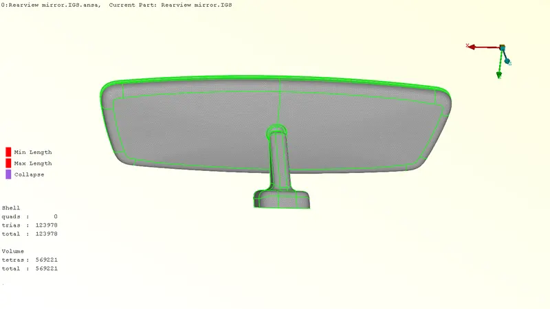
Figure-18: No off elements after 3D meshing all part - Using 'i-Not' tool we can mask some elements to see how the elements captured the volume.
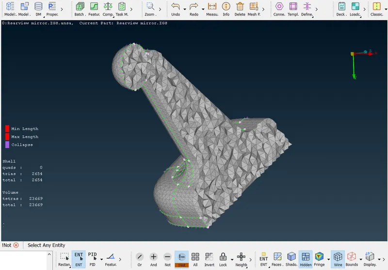
Figure-19: Using i-Not tool
RESULT:
The 3D tetra meshing is done for the Rear-view mirror model by converting 2D elements to 3D in the defined volume.
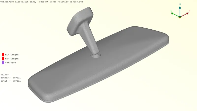
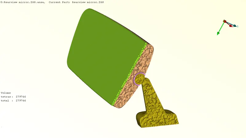
Figure-20: Final Meshed Model Images
LEARNING OUTCOME:
- Meshing 2D elements in the given model by satisfying criteria. (Use of tria and ortho tria).
- Creation of 3D elements in defined volume by converting 2D elements to 3D.
- Checking and correcting element quality failure, geometry etc.
CONCLUSION:
This challenge is very helpful for understanding about Solid meshing, how 2D elements are converted into 3D tetra elements, how the errors are rectified, different tools and its uses etc.