Week- 5 - Solid meshing
Week- 5 - Solid meshing of Rear view mirror component using ANSA
Aim:-
For the given rearview mirror component, tetra meshing should be done for the given quality criterias.
Quality Criterias:-
|
S.No |
Quality Criteria |
Value |
|
1 |
Target/Average length |
1 |
|
2 |
Minimum Length |
0.5 |
|
3 |
Maximum Length |
2 |
Use tetra elements to mesh the Volumes defined in the model and check for the below quality after Volume meshing.
|
S.No |
Quality Criteria |
Value |
|
1 |
Tet collapse |
0.2 |
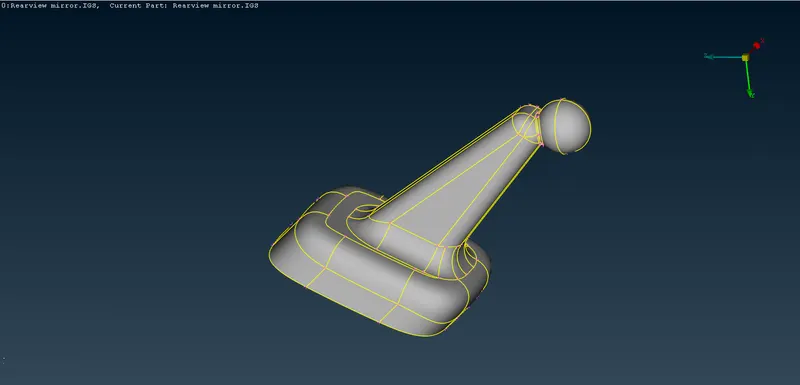
COMPONENT GIVEN FOR MESHING:-
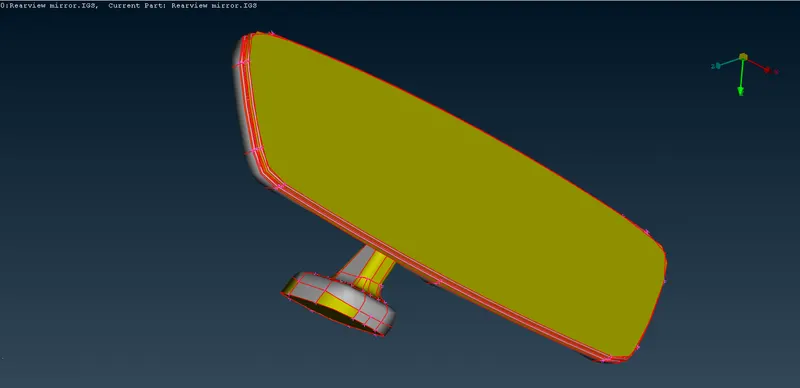
Before getting into the meshing, proper 'Topo' should be given for the component and the CAD model is checked for the geometry errors.
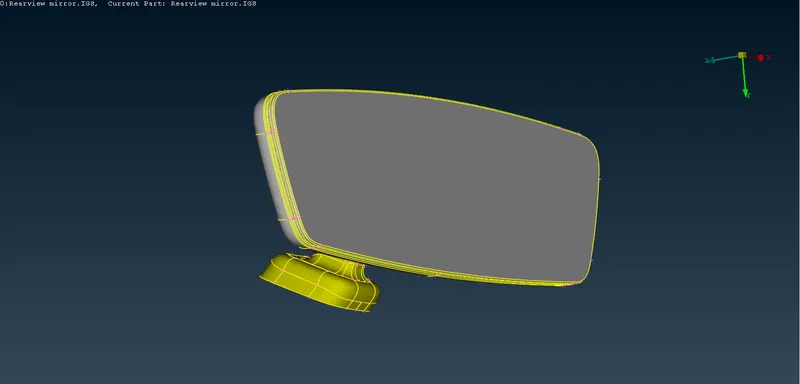
Choose Faces --->Topo command to provide the Topo for the component. After providing the topo for the given component, all the single cons are removed and the component will be ready for the geometry check as follows:-
Geometry Checks:-
Then the important step is to check the geometry of the CAD model. This will helps us to clear all the surface errors, unwanted cons and also for any dissruptions placed in the CAD model.
This can be done by giving the command Tools ---> Checks ---> Geometry. And when you check for the geometry, some of the errors will be thrown out by ANSA.
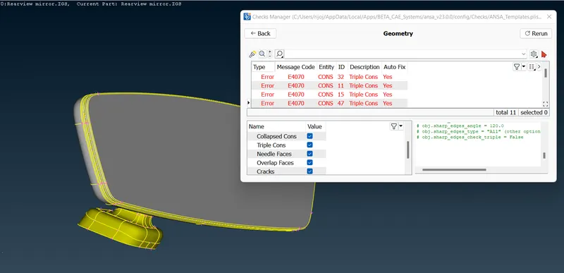
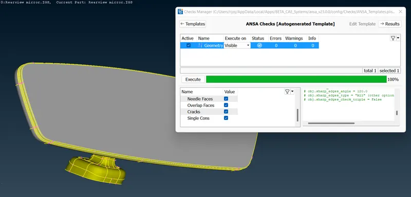
Some of these errors can be automatically resolved by the ANSA by using the command Right click + Fix in the geometry check dialog box.
After all the errors are fixed, Now our CAD geometry will be ready for solid meshing.
SEPERATE PID's:-
The entire component is divided into four PID's and the meshing will be done indiviually to all the components. The components are given as follows:-
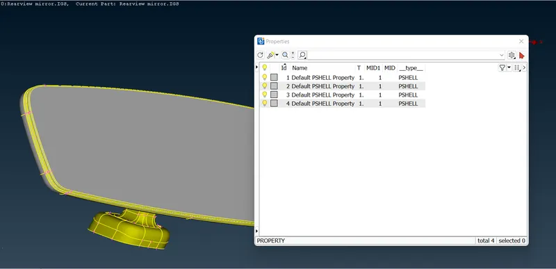
Component 1:-
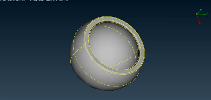
Component 2:-
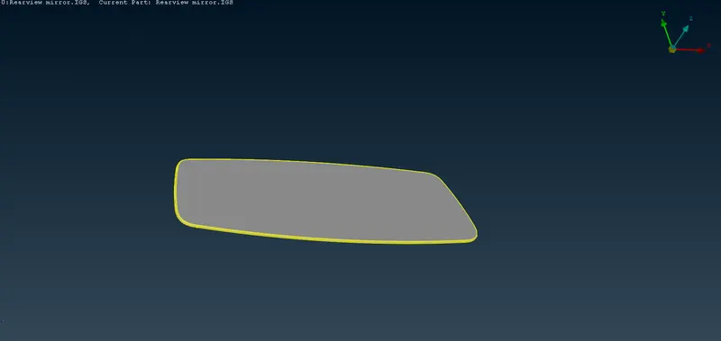
Component 3:-
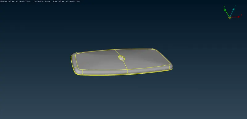
Component 4:-
PROVIDING QUALITY CRITERIAS:-
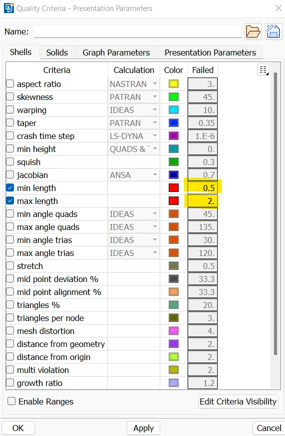
CAD model is now ready for the meshnig. And for that the quality criteria for the mesh is defined using the command Utilities ---> Quality Criteria ( or by clicking F11 )
The quality criteria dialog box will appear as follows and our qiven quality criterias are defined in the dialog box.
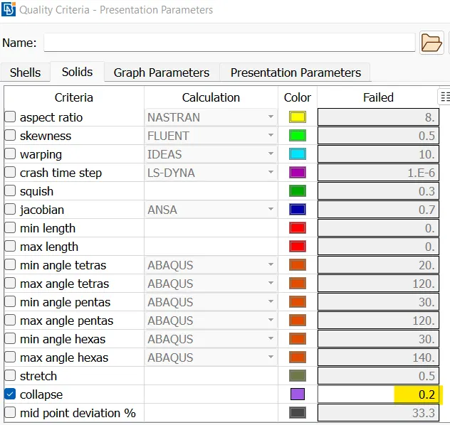
Similarly for Solid meshing, the 'Solids' tab is chosen from the same dialog box and the 'Tet Collapse' quality criteria is provided.
MESH PARAMETERS:-
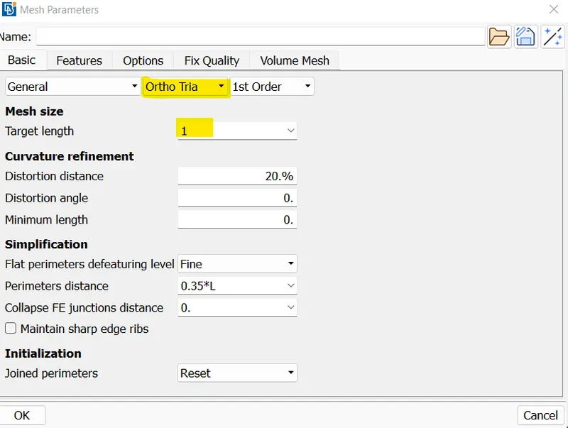
After providing the quality criterias, the meshparameters are provided prior to the meshing of component.
Go to Utilities ---> Mesh parameters and the mesh parameter dialog box will appear. Choose, the Target Value as 1 and the type of mesh as 'Ortho tria'
SOLID MESHING:-
After when all the quality criterias and meshing parameters are provided, we can start the meshing for the component.
Go to 'Mesh' module and choose 'Spotmesh' option. Once you choose the mesh option, the following options list will get visible in the bottom of the module.
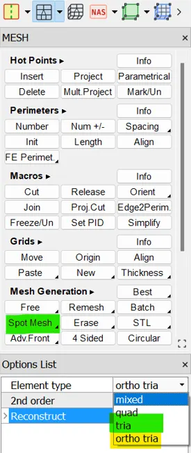
The types of mesh can be choosed according to the CAD geometry. For all the curved surfaces 'Ortho tria' mesh is suitably followed and for the flat kind of surfaces we can choose 'tria' mesh.
And the meshing should be done in a step by step manner. First all the curved faces can be selected and ortho tria mesh is provided and then for the flat surfaces tria mesh is provided accordinglly.
'Reconstruct' command is used to reconstruct the improper mesh flow if happened.
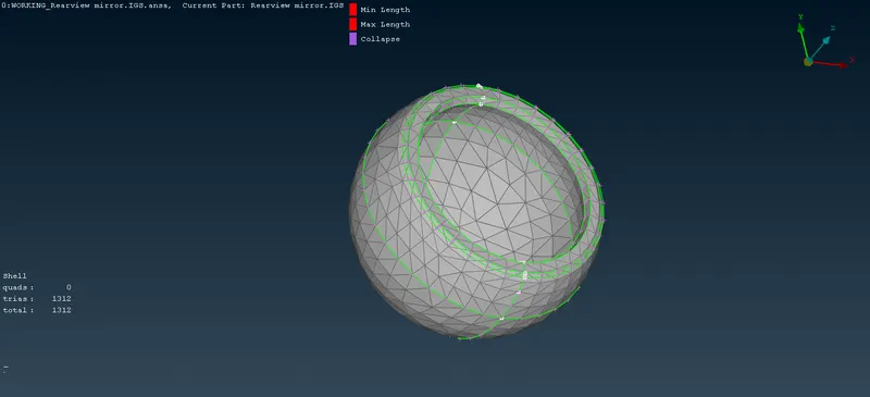
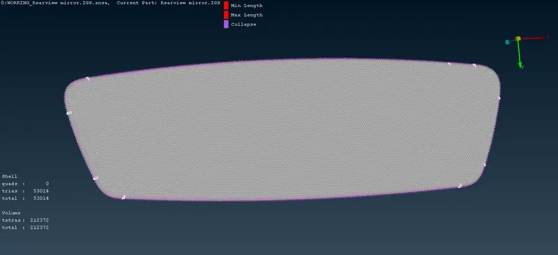
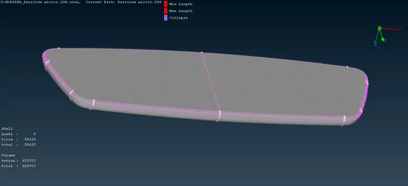
After meshing, the components will appear as follows:-
Component 1:-
Component 2:-
Component 3:-
Component 4:-
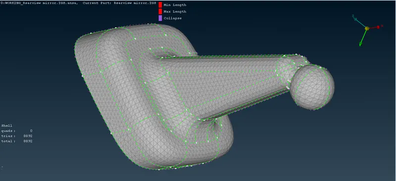
INCLUDING VOLUME WITH THE HELP OF TETRA MESH:-
Now when the meshing is done, only the outer surface of the solid component is meshed and the inner surface will be still in a hollow shape.
Now the volume mesh should be provided for the component. Go to 'Volume mesh' module.
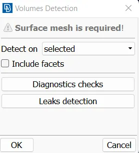
First step is to define the vomule of the component. This is done by choosing 'Volumes ---> define' , and the component is selected and the volume PID is created.
And hence the volume PID is created for all the components as follows:-
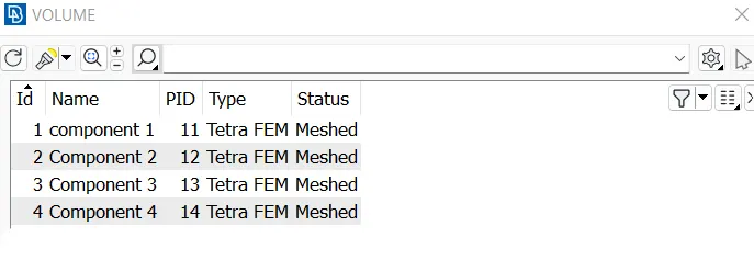
Now its time to provide the Volume mesh to the solid component.
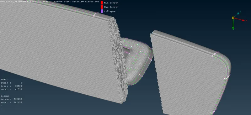
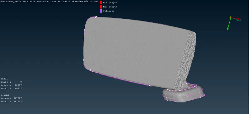
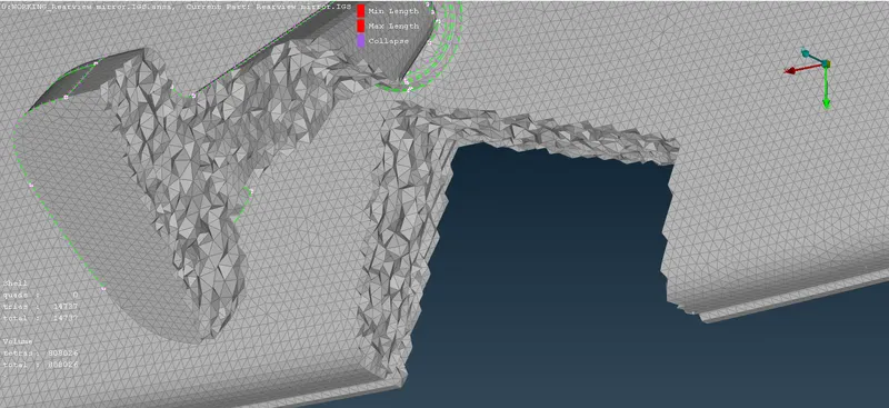
Choose Volume mesh ---> Unstructures Mesh---> Tetra FEM and then select the components indiviually and hence the volumw mesh will be done to all the components. Now to visualize the volume mesh we can cut the solid using 'Not' option and the volume mesh will appear as follows:
Learning Outcomes:-
- Learned how to mesh the solid component
- Learned the major differences between Ortho tria and Tria elements mesh
- Also learned the Tetra Rapid and Tetra Fem algorithms used for meshing
Conclusion:-
Hence the given solid component is meshed properly volumetrically using the volume mesh and all the given quality criterias are achieved.
CLICK THE LINK BELOW TO SEE THE COMPLETED MODEL:
ANSA MODEL LINK:- https://drive.google.com/file/d/1WJ3N4jHODYx24fyQfesi42eUP_Xp7EXG/view?usp=sharing
(NOTE:- THE .stp FILE IS NOT GETTING UPLOADED THROUGH THE ANSWER BOX. SO I HAVE SHARED IT WITH MY DRIVE AND I HAVE GIVEN THE LINK ABOVE)