Week- 5 - Solid meshing
Report on Week 5 Challenge Solid meshing
Aim:
For the given Rear view mirror component, check for the geometrical errors and mesh the Surfaces with the given 2D element Quality criteria are given below.
Objective:
- Extracting of the model in ANSA.
- Geometry check-up and to define mesh parameters and quality criteria.
- Cleaning and correcting the model geometry.
- Use Shell mesh to surface meshing the components and then volume mesh the components.
- Interfacing with ANSA v22.1.0.
Given data:
|
S.No |
Quality Criteria |
Value |
|
1 |
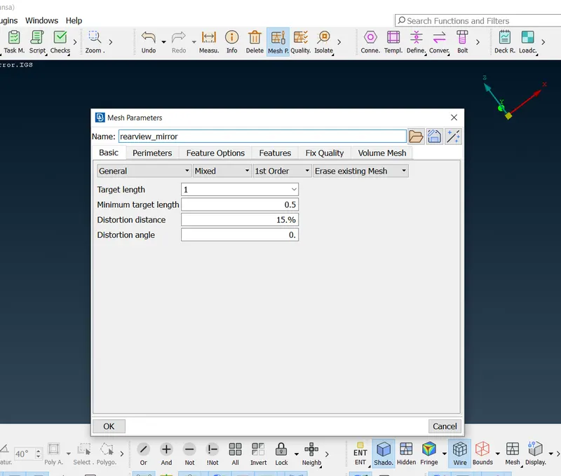
Target/Average length |
1 |
|
2 |
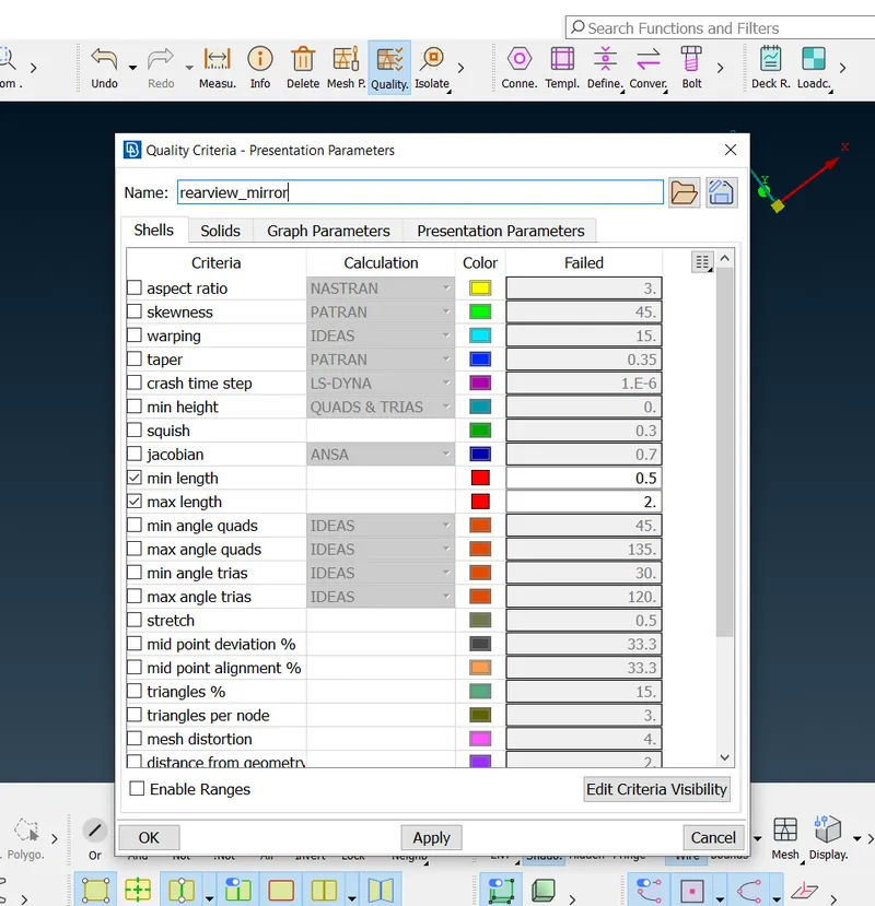
Minimum Length |
0.5 |
|
3 |
Maximum Length |
2 |
Use tetra elements to mesh the Volumes defined in the model and check for the below quality after Volume meshing.
|
S.No |
Quality Criteria |
Value |
|
1 |
Tet collapse |
0.2 |
Procedure:
- Firstly we need to import the model name as Rear view mirror.IGS CAD file.
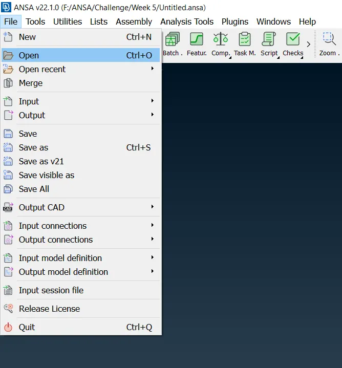
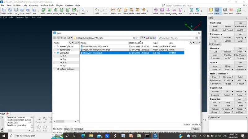
- Go to the file in taskbar >> open >> select file >> click on open.
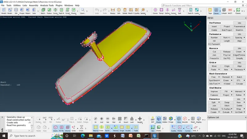
- After opening it will get a display in the geometry region.
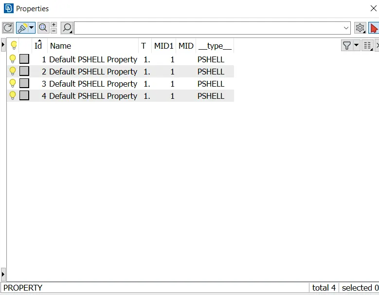
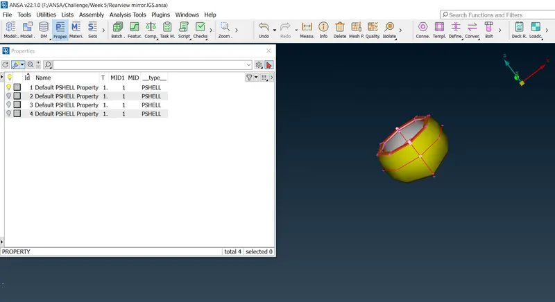
- Now we opened the property and come to know that there are four components of the rearview mirror we will mesh them one by one.
- We mesh the model by meshing each component separately. Make one visible and the other hiding.
- Before starting mesh we add mesh parameters and quality criteria for model meshing as given.
- Go to utilities >> click on Mesh Parameters then the pop-up tab will open. Put the all parameters given and then saved the file for future opening.
- Foe quality criteria, Go to utilities >> click on Quality Criteria then pop up tab will open. Put all the criteria given then apply and saved the file for future opening.
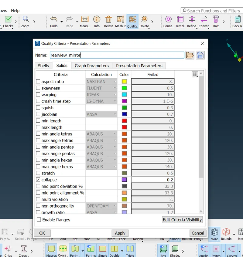
- Before going to mesh we will go for some operations on models cons and geometry check.
- We will give a cons resolution. Go to classic mesh >> perimeters >> length >> select full content by dragging the rectangle with the left click of the mouse.
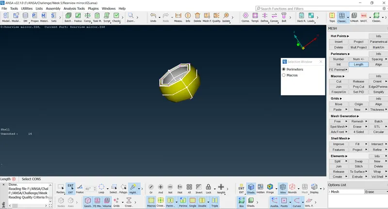
- Hit the middle mouse button >> put the length as 1 >> hit the middle mouse button. Then cons resolution is done.
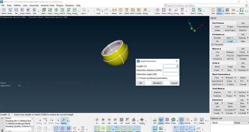
- Then we see the red edges in the model which means there is no connectivity between surfaces. To get it we will use the see topo option.
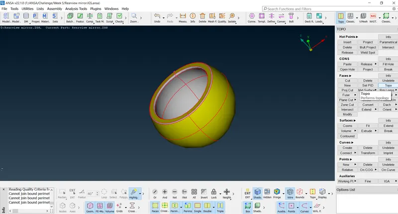
- Go to topo module >> faces >> topo >> select edges >> middle mouse click >> it will get connectivity.
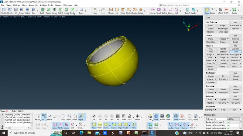
- We will orient the model. Go to top module >> faces >> orient.
- Now we will go for geometry check. Go to tools >> checks >> geometry >> check single con >> execute.

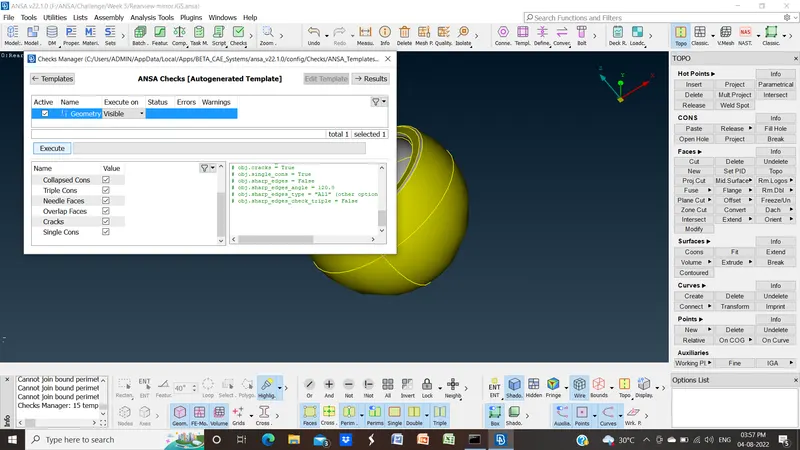
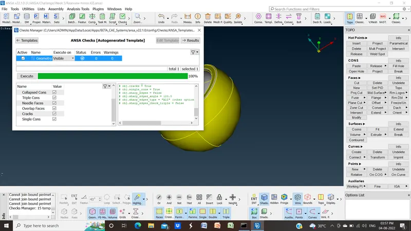
- There is no geometry defect. Now we look for lines that are less distance between them than the minimum length. We are going to use measures from utilities. If we any of them we need to join them.
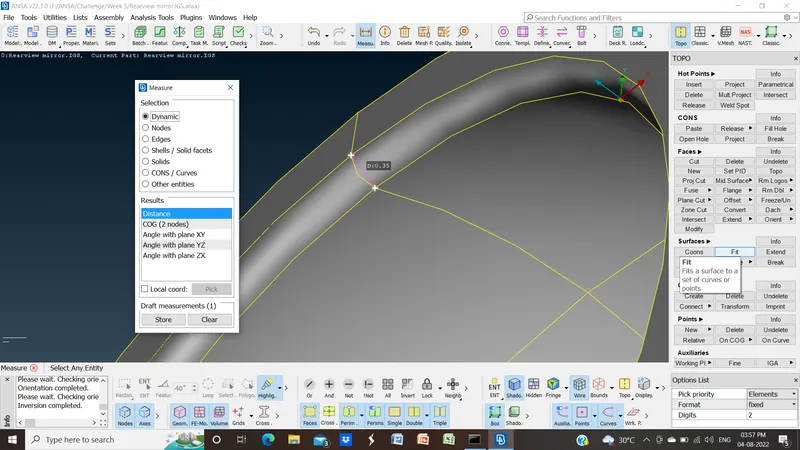
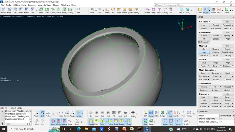
- These are the mandatory checks and operations we have to perform on the model before going to mesh. Those are cons resolution, geometry checks, topo and orient, and minimum length checkups. We are going to perform it in every component of this model.
- Now we will be going to mesh the component. Firstly we will mesh the surface of the component.
- For mesh go-to classic mesh module >> mesh generation >> best >> select the area. For flat surfaces, we are going to use trias and for curve surfaces, we are going to use ortho tria as it covers curve surfaces better.
- After the surface meshing we are going to define the volume of mesh. For that go to volume mesh module >> define >> select visible >> hit ok.
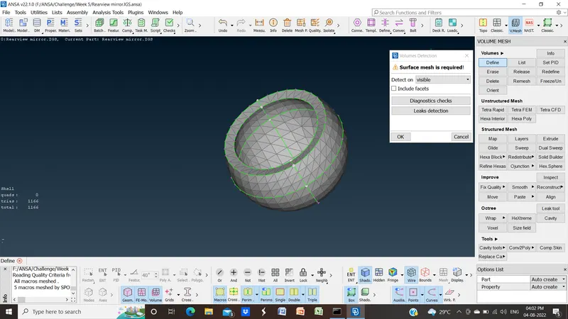
- It will create volume property automatically. Then, we will go to volume mesh module >> unstructured mesh >> tetra rapid.
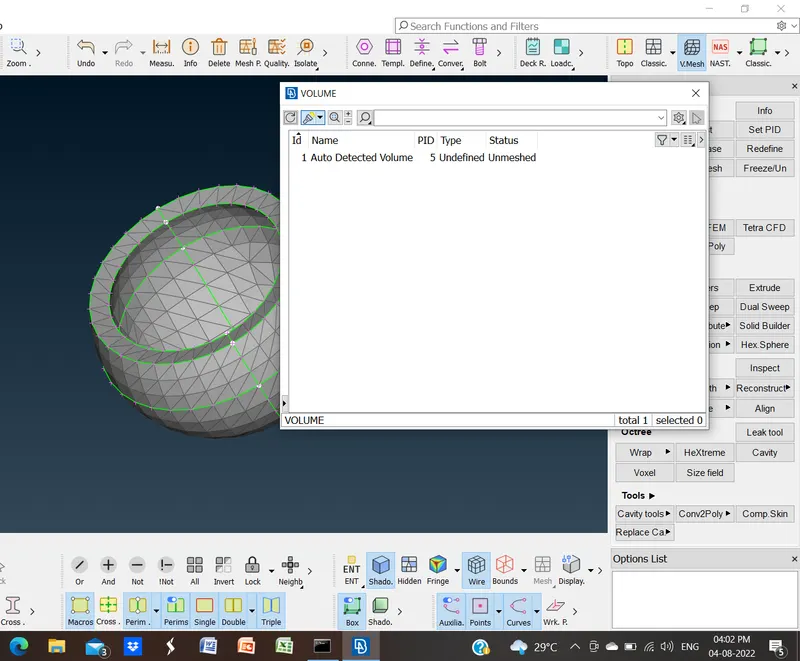
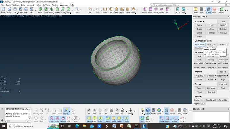
- Then we are going to check for off elements in mesh means elements that are not satisfying quality criteria.
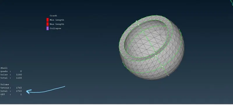
- Double click on it will show the off element. If the element is collapsed to fix it go to volume mesh module >> improve >> fix quality >> select the off element >> hit the middle mouse button it will fix the off element.
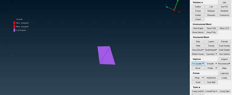 Off element
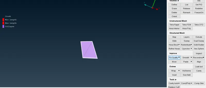 fixing quality
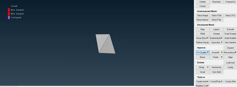 fixed element
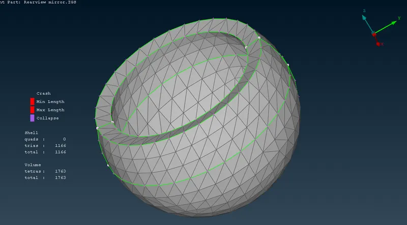
- Now one component is meshed fully with shell and volume mesh to achieve solid meshing. Further, we will mesh the remaining components in the same manner.
- Now for the next component we will repeat almost the same procedure.
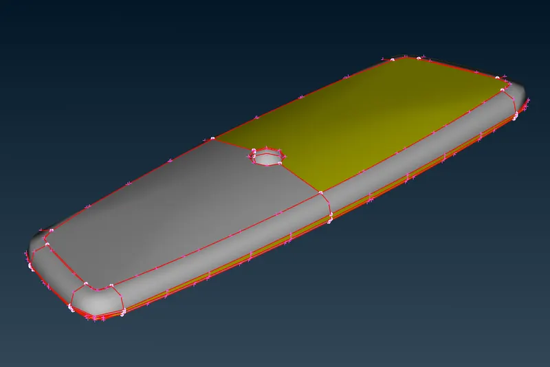
On importing
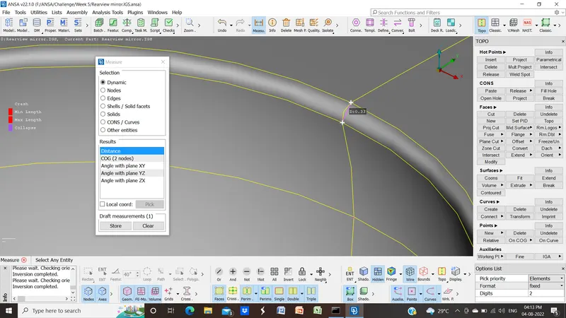
Measuring distances between feature lines
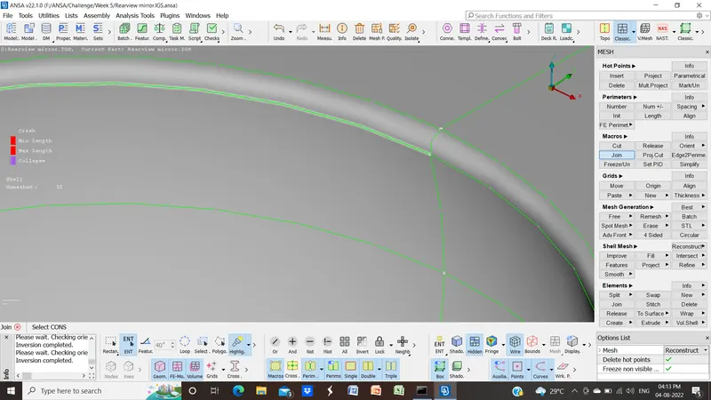
Joining the surfaces
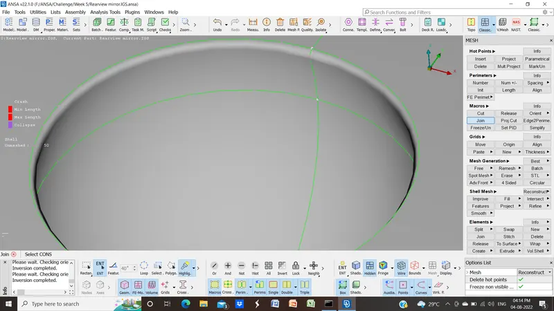
After joining
- After meshing we faced some off elements for max length we fix them by splitting.
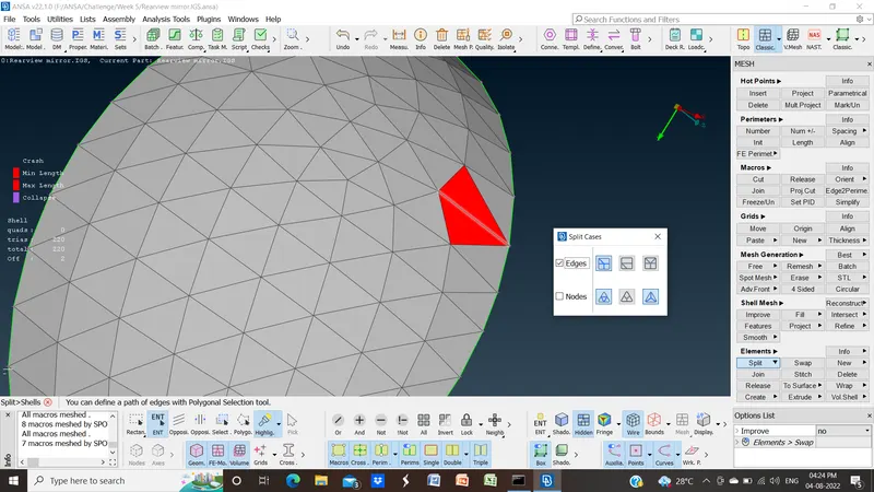
Off elements
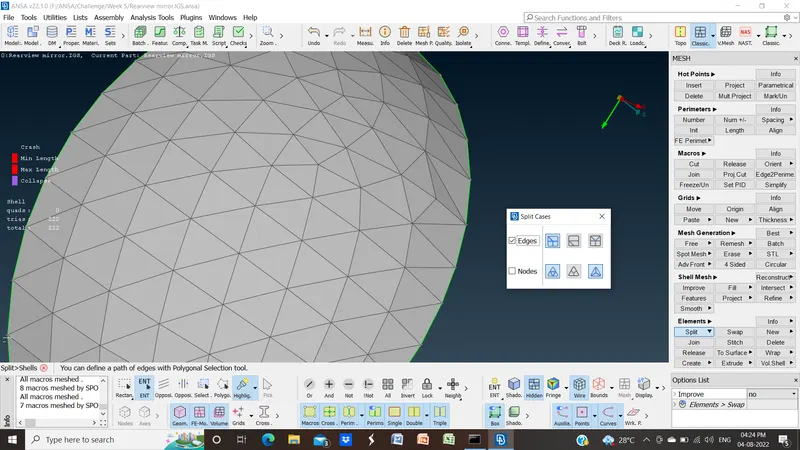
Fix them using split
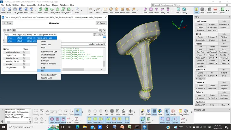
- For the last component during geometry check we find some geometric errors. To fix then click on one element >> ctrl+A to select all the errors >> right click >> fix.
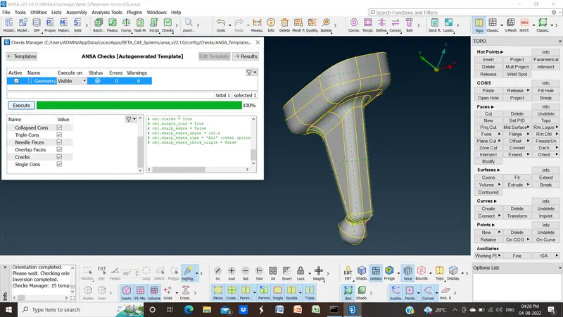
After fixing there is no error
Results:
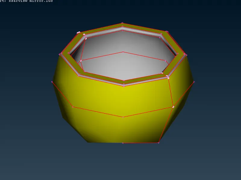
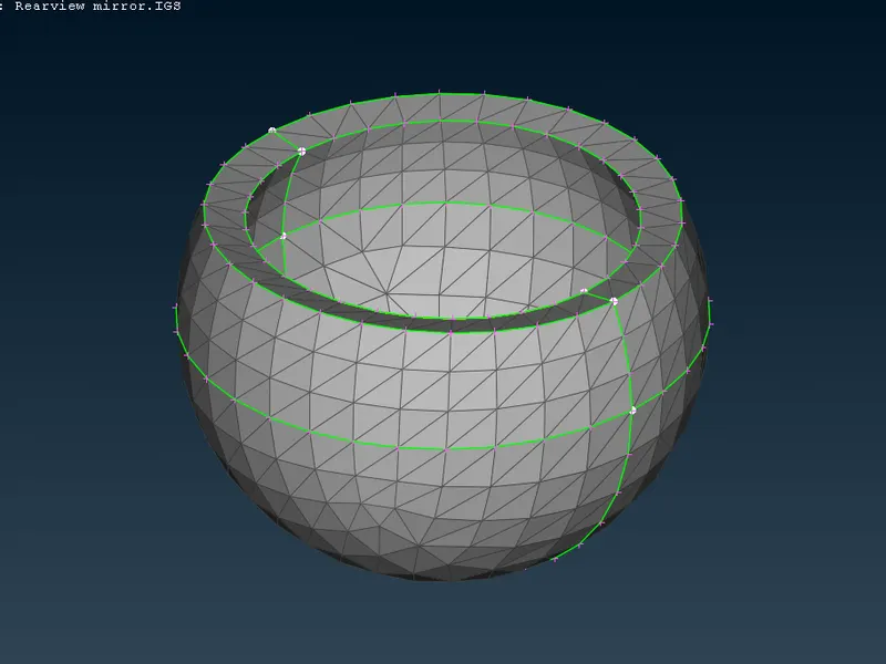
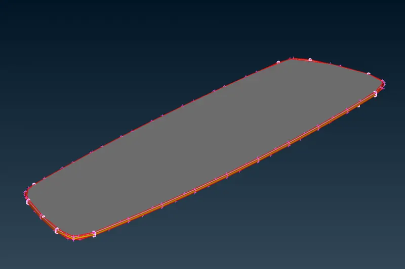
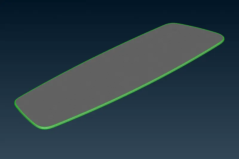
For component:
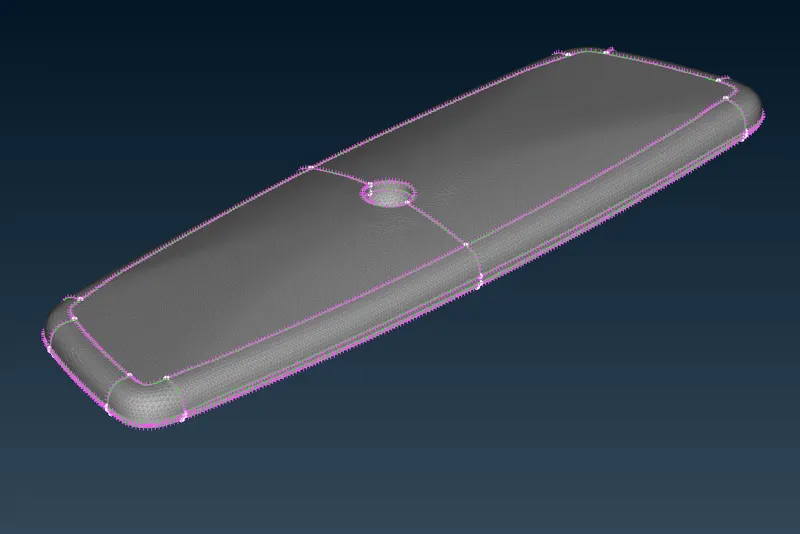
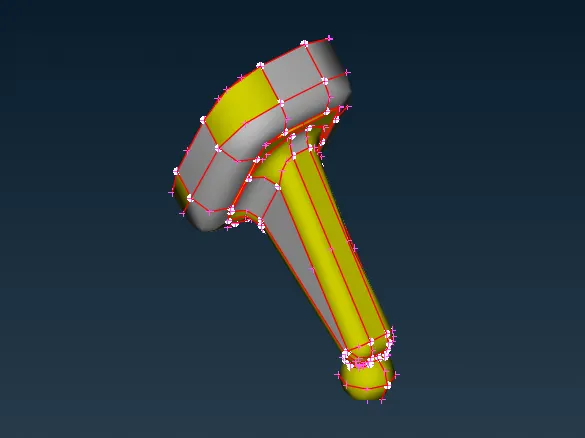
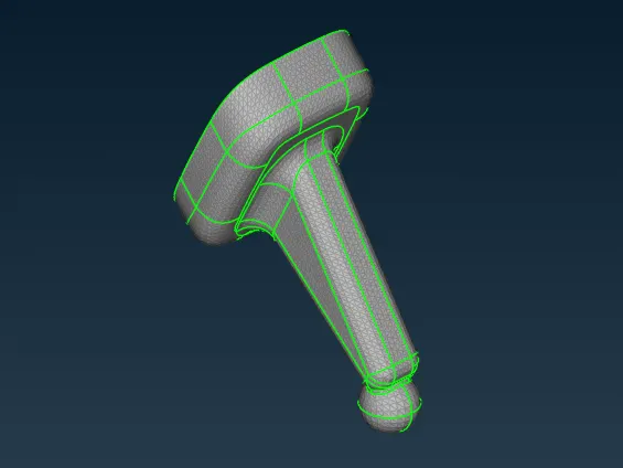
Model:
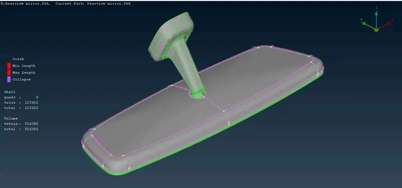
You can see there are no off elements in both shell mesh and volume mesh so quality criteria are satisfied.
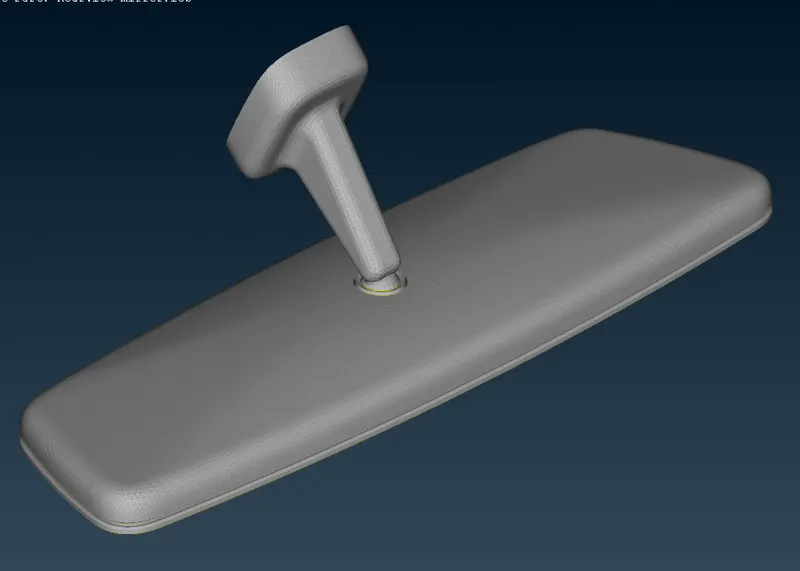
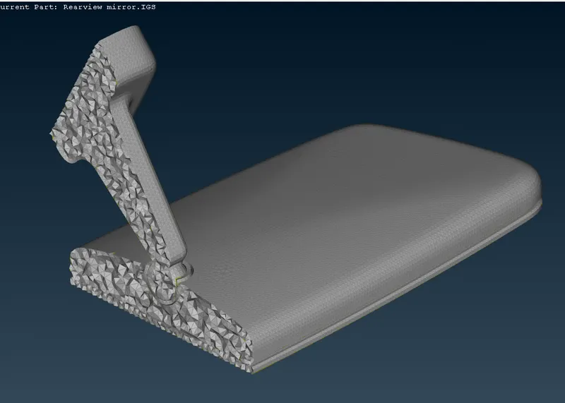
In the above image, you can see volume or solid is also mesh sing tetrahedron elements.
Learning Outcomes:
- We learn how to mesh solid/volume.
- Use of different tools related to volume mesh.
- Learn to deal with elemental failure in solid meshing.
- Use of tria and ortho tria elements to mesh the flat and curve surfaces.
Conclusion:
In this challenge, we learn how to mesh solid models using different tools present in the Topo module, Classic mesh module & Volume mesh module. Also, deal with different failures in the solid mesh.