Week 4-1D Element Creation Challenge
Report on Week 4 challenge 1D Element Creation in hypermesh
Aim:
Using different tools in HyperWorks mesh the Given component with the Size of 5 Units. Create 1D elements on the given component with the given cross-section and DOFs.
Objectives:
1. Meshing the given component with the size of 5 units.
Procedure:
- Import the given model as geometry.
- Select IGES format > select the model > click on import.
- For meshing the component, to make it easy to process and mesh we are going to extract a midsurafce.
- Our model is symmetric so midsurfacing is very easy.
- Click on Geom > midsurface > auto midsurface > select the component one > extract > select second component > extract
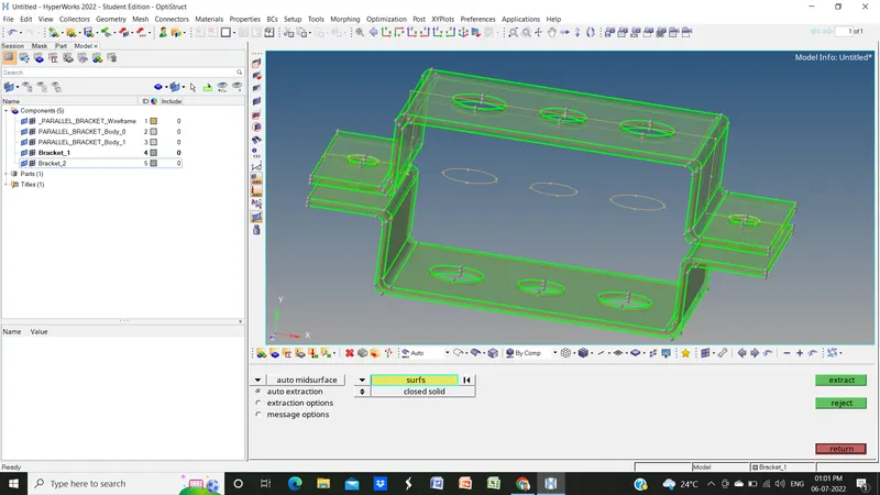
- Now rename the midsurface extracted for both brackets in the model window.
- Now delete the solid part in the geometry using the delete function or pressing shortcut key F2.
- Select solid > click on it > select all > delete entity.
- Now also delete the other components other than the midsurface in the model window.
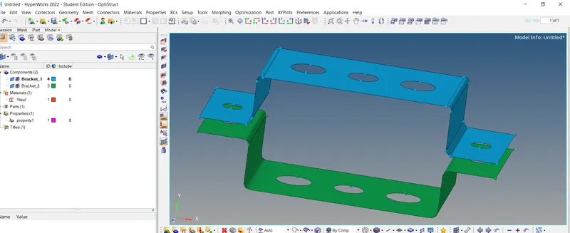
- Before meshing go-to quick edit > add washer split to each hole > offset value 5 > select holes.
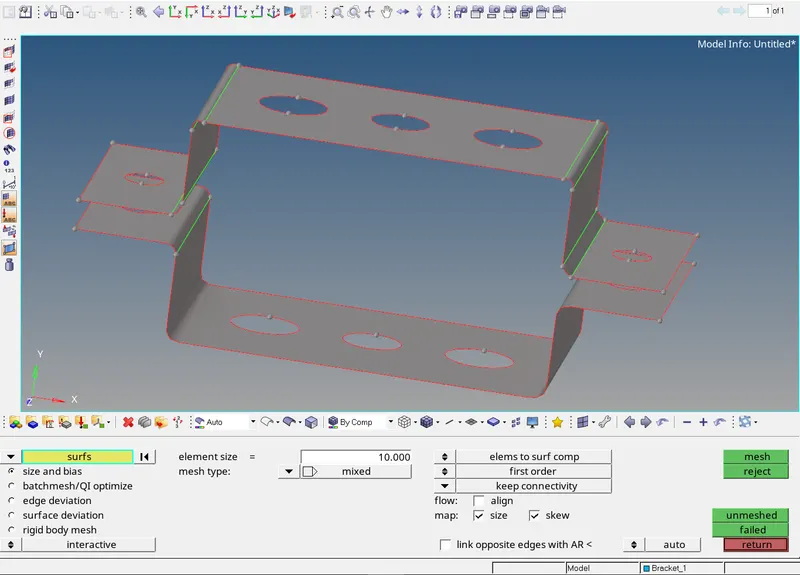
- Now go to 2D > automesh > put element size 5 > mesh type mixed > surfs > displayed > mesh.
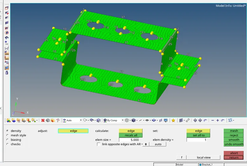
- Also equalize the number of nodes in the washer split and hole.
- Create material as steel and property for bracket 1 and bracket 2.
2. Create Rod element whose translational DOF should be constrained with RBE2 link and cross-section: BOX dimension a=12mm , b=10mm & thickness t= 0.75mm.
Procedure:
- We will create all three elements across three holes of brackets.
- Go to 1D > rigid > deselect the rotational dofs > click on nodes > multiple nodes > calculated nodes > nodes by path > select nodes on washer split and hole > create.


- Repeat the above procedure for bracket 2 also to create the RBE2 link.
- Now add rod element across the RBE2 link.
- Go to 1D > rods > select elements type as CROD > select nodes > create.
- For cross-section go to HyperBeam > standard section > select standard section type as thinwalled box, then it will automatically open hyper beam view put the dimension and create.
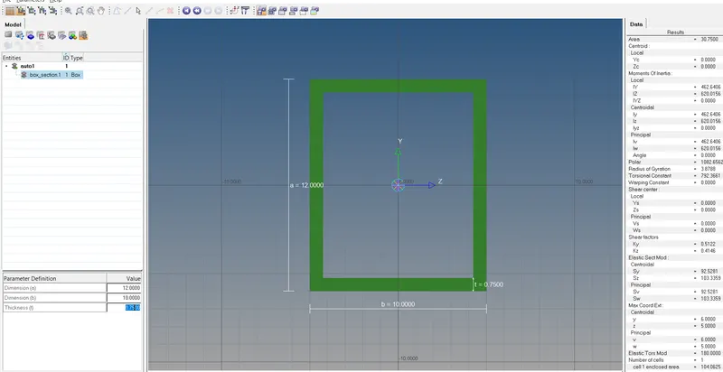
- Create a property for rod elements and update all the properties like material as steel, cross-section, and card image as PROD.
- To update cross section to rod element go to rods > update > property as Rod > select checkbox of properties to be update > update .
- This is how we created elements with links and cross-section.
- Similar process will be followed for the other element addition.
3. Create Beam element with RBE3 link whose all DOFs constrained of I cross-section of dimension a=8mm , b=10mm, c=8.5mm, t1=0.75mm, t2=0.6mm, t3=0.6mm.
Procedure:
- To create RBE3 link go to 1D > rbe3 > click on nodes > multiple nodes > calculated nodes > nodes by path > select nodes on whasher split and hole > create.
- Repeat the above procedure for bracket 2 also to create the RBE3 link.
- Now add beam element across the RBE3 link.
- Go to 1D > bars > select elemts type as CBEAM > select nodes > create.
- For cross-section go to HyperBeam > standard section > select standard section type as standard I section, then it will automatically open hyper beam view put the dimension and create.
- Create a property for beam element and update all the properties like material as a steel, cross section, and card image as PBEAM.
- To update cross section to beam element go to bar > update > property as beam > select checkbox of properties to be update > update .
4. Create Bar element with RBE3 link constrained with only x & y DOFs of cross section X with dimensions DIM1=5mm , DIM2=1.2mm, DIM3=10mm, DIM4=1.2mm.
Procedure:
- Go to 1D > rigid > deselect the dof3 and dof6 > click on nodes > multiple nodes > calculated nodes > nodes by path > select nodes on whasher split and hole > create.
- Repeat the above procedure for bracket 2 also to create RBE3the link.
- Now add a bar element across the RBE3 link.
- Go to 1D > bars > select elemts type as CBAR> select nodes > create.
- For cross section go to HyperBeam > standard section > select standard library as optistuct > select standard section type as the cross. It will automatically open hyper beam view put the dimension and create.
- Create a property for bar element and update all the properties like material as steel, cross section, and card image as PBAR.
- To update cross section to bar element go to bar > update > property as Bar > select checkbox of properties to be update > update .
5. Apply the mass of magnitude with 10 with the RBE2 link.
Go to 1D > masses > put mass value as 10 > select the node at RBE2 link > create.
6. Join the two components i.e. bracket with spring elements.
Go to 1D > springs > select one node at bracket_1 and one on bracket_2 then will get created automatically. We join the components from two ends with spring elements.
Results:
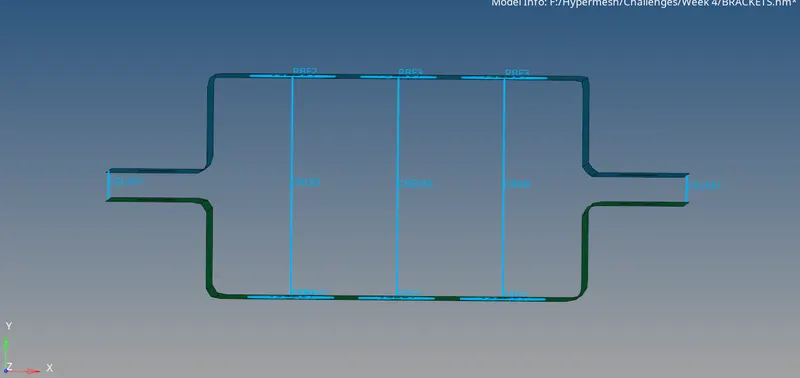
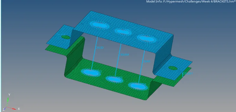
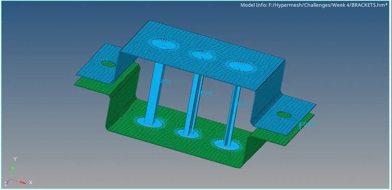
For detailed view of element cross section click 1D detail representation.
THANK YOU