Week- 5 - Solid meshing
AIM
- To check the given rearview mirror component for geometrical errors and mesh the surfaces using the given 2D quality criteria.
- To create a 3D tetra mesh by providing volume to the 2D surface mesh.
- To check the volume tetra mesh for tet collapse.
PROCEDURE
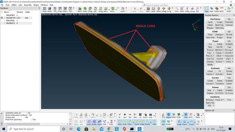
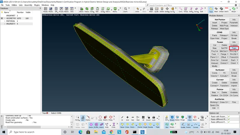
- To begin with the component is cleaned to rectify the single cons present by using the 'Topo' tool as shown in the images below.
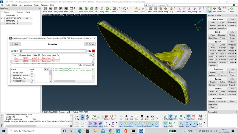
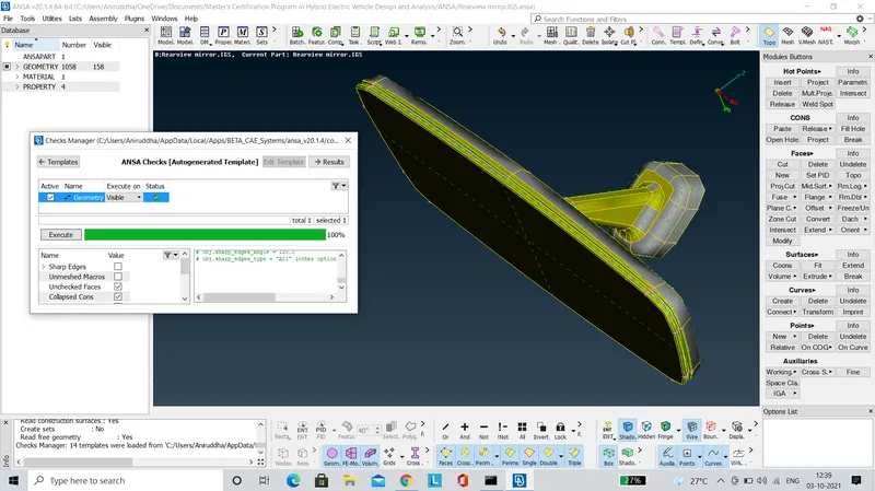
- The 'Geometry Check' tool is also used to identify hidden geometric irregularities and rectify the same as shown in the images below.
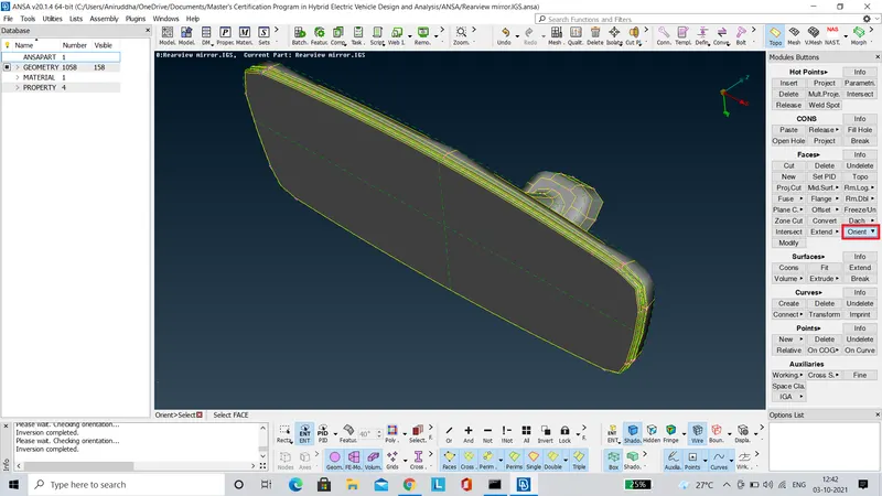
- Then the 'Orient' tool is used to make sure that normals of all the surfaces are oriented in the appropriate direction. This process is executed to make sure that the mesh generated on various surfaces reacts uniformly to the external loads.
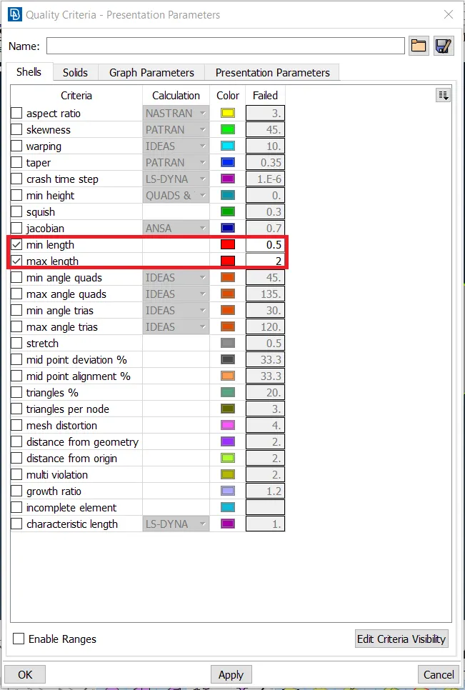
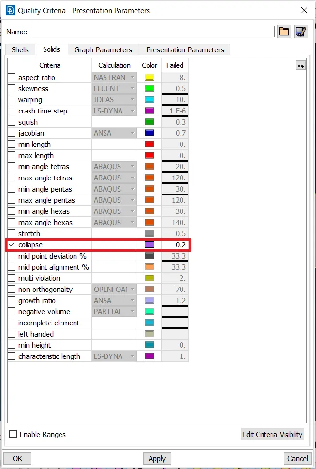
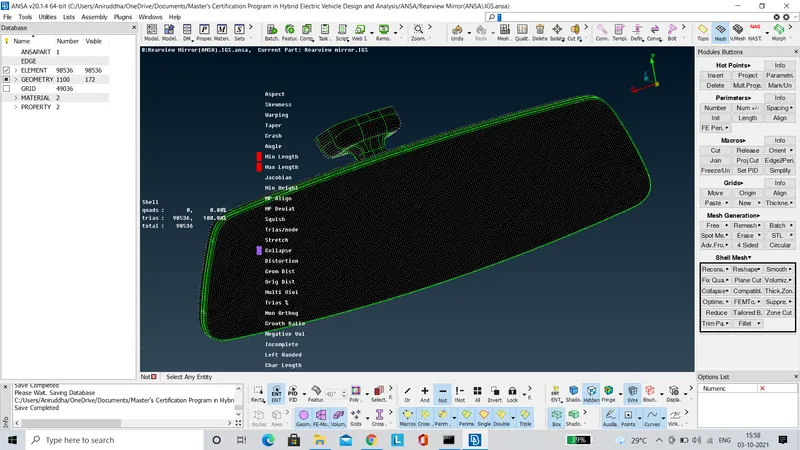
- The quality criteria for the 2D and 3D mesh is assigned as shown in the images below. Only minimum and maximum length parameters are considered for 2D mesh, whereas for 3D mesh only tet collapse is considered.
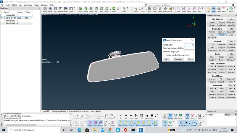
- Before proceeding with the meshing process it is crucial to set the length parameters as per the given target element length which in our case is 1, as shown in the image below.
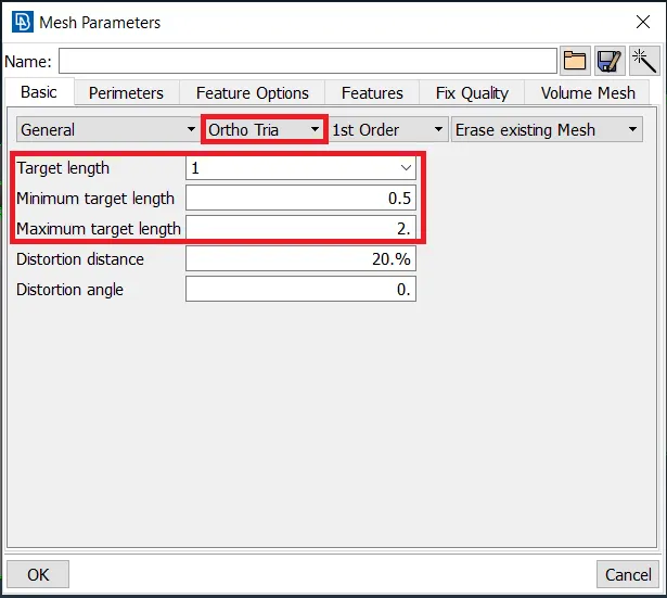
- We start the 2D meshing process by using the ortho tria elements for the curved features, since they offer better feature capturing and connectivity along curved edges. But the one drawback of meshing with ortho tria elements is that the processing time increases by many folds. The mesh parameters are set accordingly as shown in the image below.
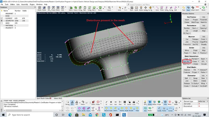
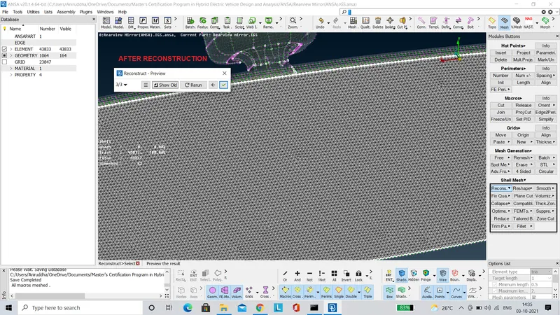
- The 'Spot Mesh' tool is used for generating the mesh. The mesh generated, if not satisfactory or having any distortions can be rectified by using the 'Reconstruct' Tool.
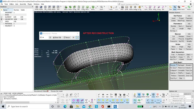
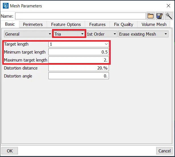
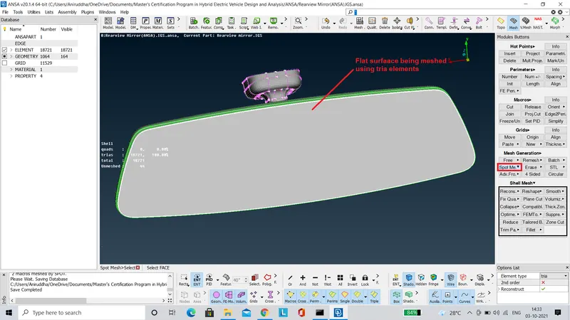
- The relatively flat surfaces are meshed using the tria elements, since in flat surfaces there is no problem pertaining to feature capturing and connectivity. Also by using tria elements wherever possible, we can cut down on the processing time. The mesh parameters are set accordingly as shown in the image below.
- The 'Spot Mesh' tool is used for generating the mesh. The mesh generated, if not satisfactory or having any distortions can be rectified by using the 'Reconstruct' Tool.
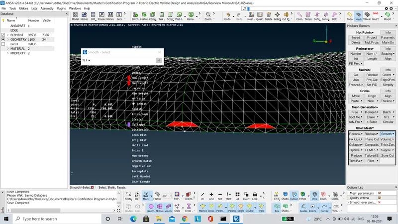
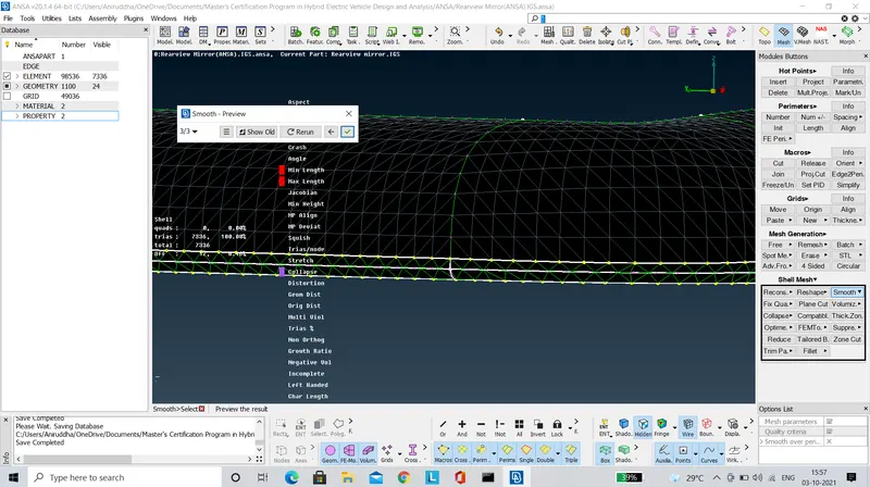
- The minimum and maximum length errors are rectified using the 'Smooth' tool as shown in the images below.
- Similarly all the elements failing for quality criteria are rectified, since any failed element in the 2D mesh would result in the formation of distorted tetra elements while 3D(Volume) meshing.
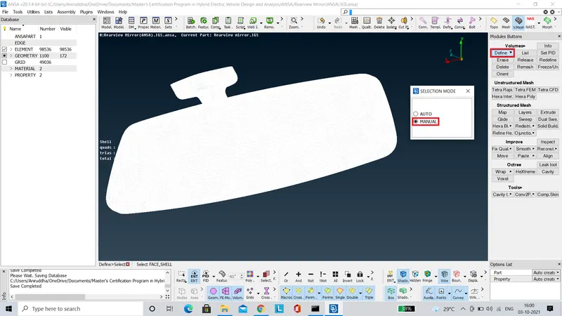
- Before proceeding with the volume meshing process, it is necessary to assign volumes to the previously generated 2D mesh using the 'Define' tool as shown in the image below.
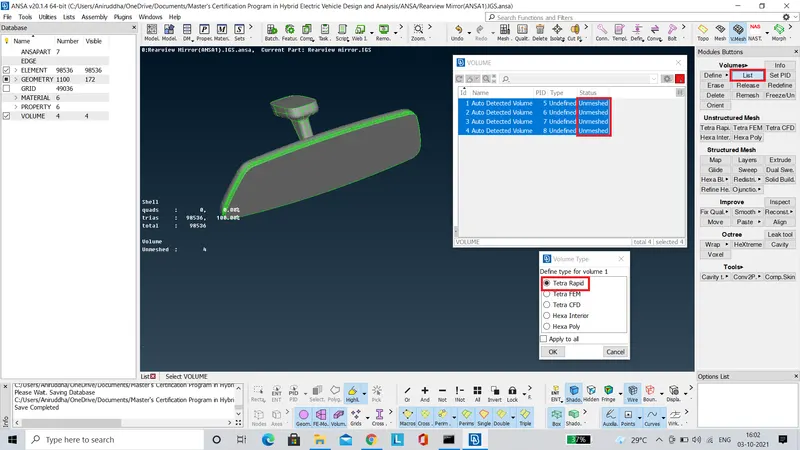
- After assigning the volumes, it can be seen that the status of the volumes appears to be 'Unmeshed'. By right clicking on the volumes list and by selecting 'Remesh' option, the volume mesh can be generated. For generating volume mesh there are two options namely 'Tetra Rapid' and 'Tetra FEM'. These two options use different algorithms to generate the volume mesh. In our case we have used the 'Tetra Rapid' option.
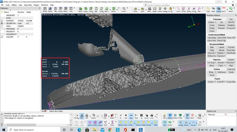
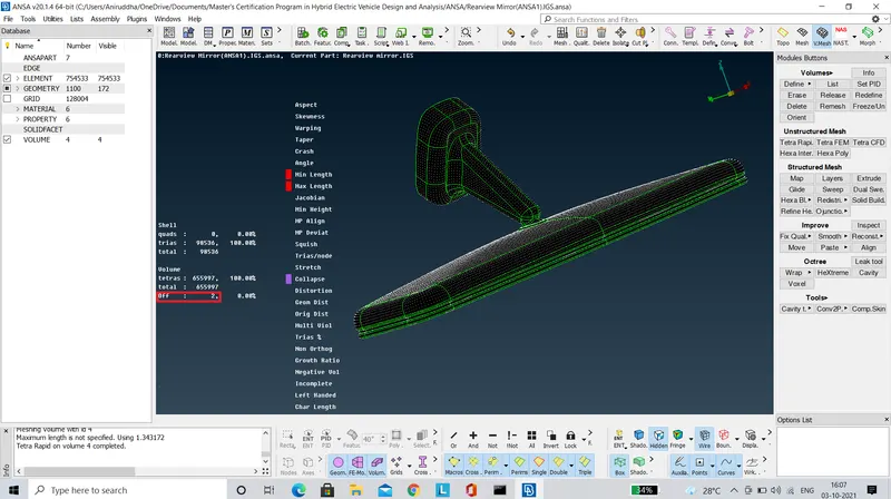
- After volume meshing, it is found that there are two elements failing for tet collapse as shown in the images below.
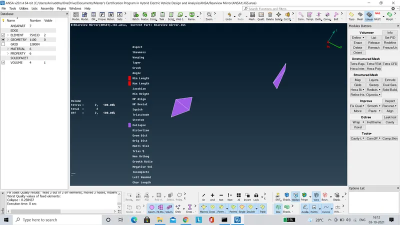
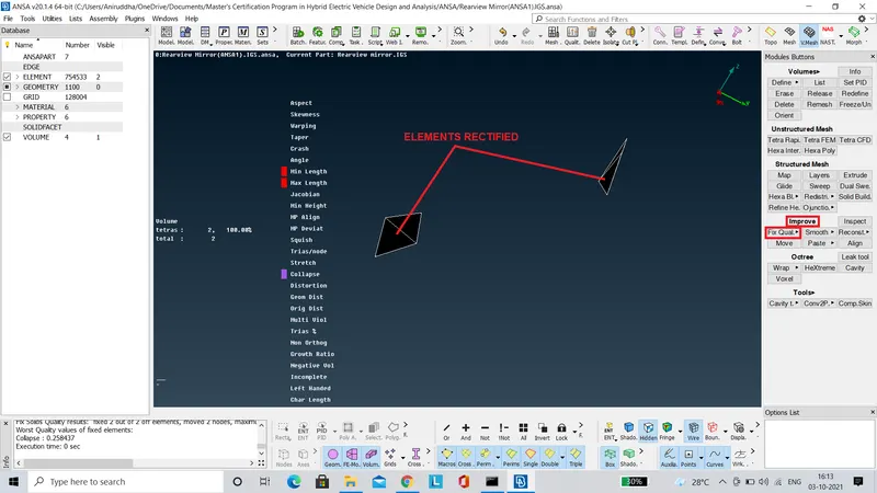
- These elements can be rectified by using the 'Fix Quality' tool under the 'Improve' panel.
LEARNING OUTCOME
- The various tools concerned with volume mesh generation and validation of quality criteria for the same were learnt during the course of this project.
CONCLUSION
- The rearview mirror component has been 3D(Volume) meshed with tetra elements as per the given quality criteria.