Week 5:- Rest Unit & Clamp Unit Design Challenge
AIM
The main moto of this challenge is to design the rest and clamp units for car panels in order to support and rest the part on the base using CATIA V5 tool.
Design process
- primarily you need to know about how to study the BIW design. You should know the basic process of Weld shop, Weld equipment's for BIW design and below detail for Fixture concept design.
Fixture Concept Study
Process considerations
Usage of Standard components
Clamping and supporting arrangement
Locating Arrangement - Maintaining X, Y, & Z co-ordinates of locating points/Clamping points
Ease of loading & unloading.
Preparing Manufacturing Drawing (Detailing)
Fixture Design: - Input Data
i) Panel Data: CAD Models of the panels
ii) Sequence of assembly
iii) Clamping Plan
iv) Sections
v) Cycle time
vi) Base Plate
The information like how many panels to be welded, where the panel is to be clamped, supported and located, what
is the cycle time, what is the sequence of loading & unloading is derived out of the above data - CLAMP UNIT
clamp unit is a unit designed to clamp/hold the car panel with NC blocks/mylars/rest by using a pneumatic cylinder. Clamp arm, finger, Rest/backup, L-block, shims, riser, pneumatic cylinders are the typical parts of clamp uni
Toggle clamps are generally hold the car part firmly and prevent the part from distortion while carrying out the spot welding
parts of the clamp unit
1. Finger: Finger is a movable part which is used to hold the Car part from top against the Back-up and they are
usually mounted on the clamp arm.
2. L-Block: L - Shaped blocks (single or in combination) used to mount the finger to clamp arm, besides allowing
adjustment for locator pin in two directions.
3. Shim and spacer: They allow the finger to be moved to the correct XYZ locating and / or allow the customer to
make adjustments to improve the quality of their product.
4. Blade: Part onto which the aforesaid elements are attached to.
5. Blade spacer: It allows the finger to be moved to the correct location along one direction.
6. Riser: L- shaped tall block with regularly patterned holes to attach the above mentioned parts in modular way
Blade space.
- design process
there are different steps involved while designing the clamp unit.
- open catia v5, open a new assembly sheet
- save it in a seperate folder and copy the cap panel from adifferent folder and paste it in this
- and then design the raisers,L-blocks and mylers and etc.. using oart design commands
- and assemble those with car panel using snap tool and smart move command in assembly.
- after all certain process is to be done, the design is looks like below
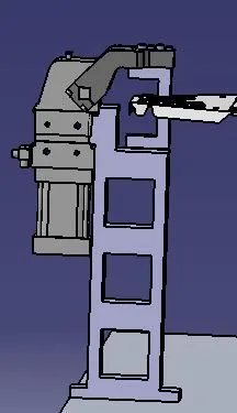
clamp unit 1
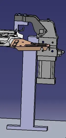
clamp unit 2
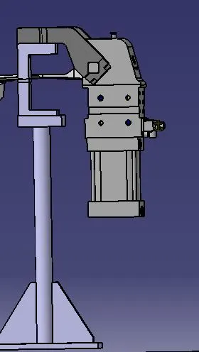
clamp unit 3
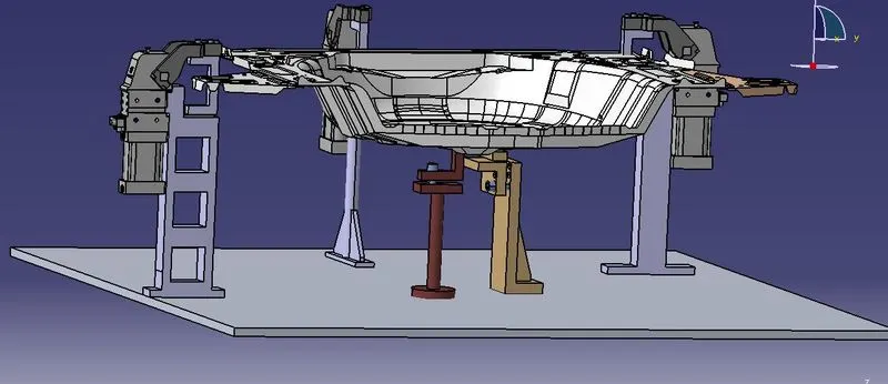
whole unit with car panel

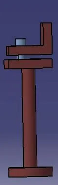
rest unit
- These units are used to rest the panel. Take an overview of the working height if you’re having manual welding. For
robotic welding also it’s important to see the working height in consideration of the robotic gun, turn table height if
manual loading is done. Put the proper gun at the spot location for all the spots near the rest unit. If process
engineer has gun shape stick to X, C or Y type of gun. Do the proper gun study and place the gun as per the GEO
or re-spot decision and operator approach. Once basic gun is placed considering the throat depth and throat gap
start building the clamp and rest block at the PLP.
Panel section creation: Take a section at PLP either in clamp opening direction or normal direction. Sections
should be normal to base. Panel section through X, Y or Z direction passing through PLP. Section will help in
finalizing the shape of clamp and rest block. Most importantly used for finalization of gun shape. Finalization of a
base plate plane – consider following things before deciding the base plate. Height of maximum and minimum weld
spot from the floor. No gun arm should touch the base plate.
Operator ergonomic while accessing all the spots. Construction of Rest Block: If standard Mylar has to be used (Few
companies make standard height and length of steel blank with few holes and dowels for clamping) then select the
proper blank size as per the requirement; consider 5 mm above the panel. As per your company or OEM, Tier 1
standard use the different standards mounting risers. Do not forgot to add the 5mm shim. If you are combining
rough locator or part sensor bracket along with the rest unit. Take necessary care means distance of rough locator
from panel. In the process of manufacturing we use Steel Aluminum, S-grun, and Plastics. And hardening is
necessary in manufacturing Mylar and Pin. - desin process of rest unit
- open catia v5, open a new assembly sheet
- save it in a seperate folder and copy the cap panel from adifferent folder and paste it in this
- and then design the raisers,L-blocks and mylers and etc.. using oart design commands
- and assemble those with car panel using snap tool and smart move command in assembly.
- after all certain process is to be done, the design is looks like below
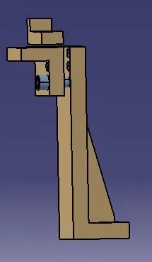
whole unit( both clamp and rest unit)
conclusion
hense the clamp and rest units are desined for given car panel as per instructions with different blocks,mylars,raisers etc...