Week 5:- Rest Unit & Clamp Unit Design Challenge
OBJECTIVE
To design 3 different types of clamp units with different risers, blades, and clamp arms. And to Design 2 Different types of rest units for the given car panel.
Abstract
I have designed different types of Power Clamp units by validating a Power Clamp Cylinder and By considering a clamping force act at each end of mylars and also designed different types of Rest Unit By considering a Holding Force for the given Car Panel. Here By considering the fundamentals of Clamp Unit design.
Software
Catia V5
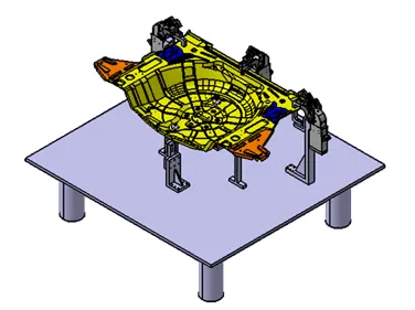
Clamp Unit
- A clamp unit is one of the units in Fixture design it Is used to hold or clamp the car panel with NC blocks/Mylars/rest by using pneumatic or hydraulic cylinders.
- Clamps arm, fingers, rest/backup, L-block, shims, risers, pneumatic cylinders are the typical parts of clamp unit.
- Clamp force should be considered while designing clamp unit
Clamp Arm
- A Clamp arm is a bought-out part, to which the movable parts are fixed. In general, a clamp arm is a part of a clamp cylinder.
Clamp Cylinder
- A Clamp Cylinder is a pneumatic device that works with pressurized air. The Clamp cylinder is used to open and close the parts fixed to the clamp arm fixed to the clamp body. Clamp arms are generally bought-out parts.
Rest Unit
- The Rest unit is used to support the car panel, also it rests the clamping force of the finger with the help of rest mylars.
- The Rest unit consists of rest mylars, shims pack, risers.
- Holding force should be considered while designing a rest unit.
- Mostly to avoid excess parts to reduce the weight & to reduce the cost of the fixture unit is combined with the clamp unit.
Rest
- Rest is an NC block, which is fixed to the unit to support the car panel, also it resists the clamping force of the finger, and thus clamps the car panel.
Finger
A Finger is an NC Block, which is mounted on the Clamp arm of the cylinder, and will press the car panels towards the rest, so it holds the car panel.
TYPES OF CLAMP UNITS:
- Power clamp unit.
- Swivel cylinder clamp unit.
In this project, I have used a power clamp unit to design.
PURPOSE OF CLAMP & REST UNIT:
The purpose of clamping tools is to securely hold the workpiece in position without obstructing the production process. High clamping forces combined with compact dimensions are therefore the most important requirements for a clamping tool. For this reason, clamps are also equipped with mechanical transmission gear units.
(3-2-1 principle) achieved by clamping & resting:
- The best & most cost-effective method of part location is referred to as the 3-2-1 method.
- . Fixtures work on of 3-2-1 principle.
- (3) Minimum: Three locator blocks to establish the part plane. Three locators or supports are placed under the workpiece. Three locators are usually positioned at the primary locating surface.
- . This restricts two axial movements downward & upward and four radial movements. Together, the three locators restrict six degrees of freedom.
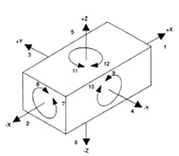
As by 3-2-1 method by introducing a minimum of 3 clamping & 3 resting blocks will restrict 6 degrees of freedom (DOF) and then 2axial movements and 4 radial movements
Design Methodology for My Project
According to my panel, I need to design 3power Clamps and 2 Rest Units so I started fixing the power clamp first, and then I started resting unit for the panel
Insert a new product in the design Tree structure and Name as P001_Z01_ST01_03_00_POWER_CLAMP_UNIT.1 and insert another sub-parts and name according to the use
CLAMP UNIT (P001_Z01_ST01_03_02_CLAMP_MYLAR)
To start the Clamp unit I started adding the clamp fingers/clamp Mylars on the rare middle of the panel I designed according to the panel positioned
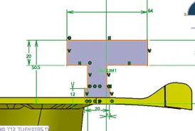
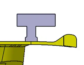
POWER_CLAMP_UNIT (APH_50_BR5_A40_T12_TUENKERS.1)
Then the next step is to insert the Power Clamp Unit is nothing but it is a brought out part which Is available in the TUNKERAS Web Page, Download what is required for the availability and insert the Power Clamp Unit and merge with the clamp Mylar and check the clearance from panel and opening and closing of the panel. That clearance needs to be checked before fixing the panel.
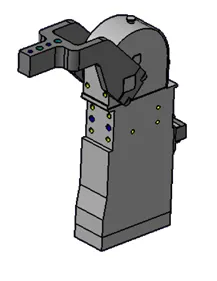
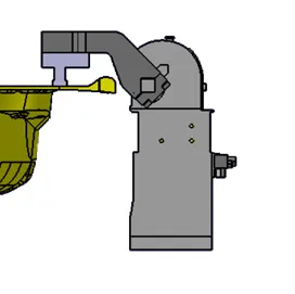
Fig-Brought out part Power Clamp Unit Fig clamp Mylar to Power clamp unit attachment with clearances
REST_MYLAR (P001_Z01_ST01_03_01_REST_MYLARS)
It is the supporting part for the panel and the Clamp Mylar and for designing the rest unit and checking the clearances of the part with related to the other parts and it is attached the Riser.
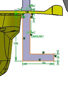
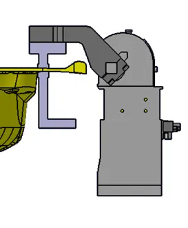
FIG:-Sketch and extruded FIG:-Attached to the panel & Clamp Mylar
RISER (P001_Z01_ST01_03_03_POWER_CLAMP_RISER)
The part which is mounted on the base plate and holds a clamp is called Riser. Riser can be Standard Part or manufactured part, it varies from project to project. A riser can be a Single part or welded part. Standard risers also have various shapes and sizes.
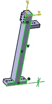
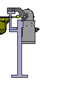
Fig Riser fig Riser with power clamp unit
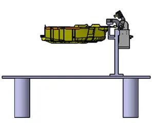
Fig final assembly of POWER_CLAMP_UNIT, CLAMP MYLAR, REST MYLAR, AND RISER for the 1st power clamp unit
The above process was repeated for the next 2 power clamp units
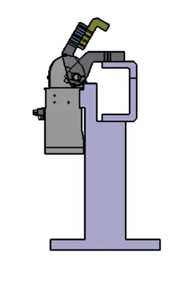
Fig power clamp unit-ll (P001_Z01_ST01_04_00_POWER_CLAMP_II)
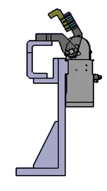
Fig power clamp unit-lll (P001_Z01_ST01_05_00_POWER_CLAMP_III)
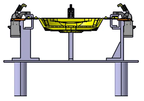
Fig complete clamp units (fr_view)
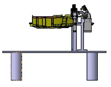
Fig complete clamp units (side_view)
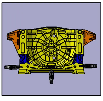
Fig complete clamp units (Top_view)
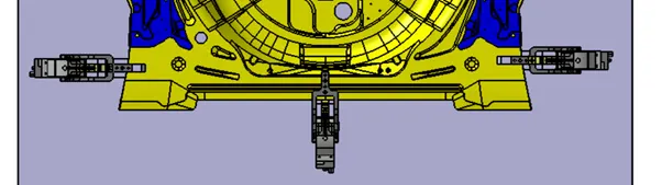
Fig complete clamp units to check the opening and closing of clamp mylar(clearances b/w clamp and panel)
From the above images clamp units designs are completed the next process is to design the Rest units
Rest Unit (P001_Z01_ST01_06_00_REST_UNIT_1)
The Rest unit consists of the Riser, blades, shims, retainers, or L-Blocks and needs to add where the support is required for the panel the rest unit is needed.
Started with rest mylar and blade and riser and Shims where ever its required
Rest Mylar(P001_Z01_ST01_06_01_REST_PIN)
It is also similar to the rest mylar used in the power clamp unit. Just we need to adjust the location of the rest mylar and need to design the connecting components like blade and Riser.
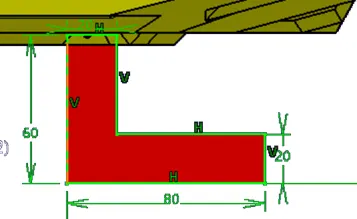
Fig Rest mylar
Blade (P001_Z01_ST01_06_02_BLADE)
The plate which connects Riser to the Clamp cylinder is named Blade. This plate plays an important role in building the unit. The plate can be of any shape. But we need to keep in mind that the plate should be as compact as possible.
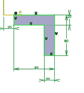
Fig Blade
RISER (P001_Z01_ST01_06_03_RISER)
The part which is mounted on the base plate and holds a clamp, is called Riser. Riser can be Standard Part or manufactured part, it varies from project to project. A riser can be a Single part or welded part. Standard risers also have various shapes and sizes.
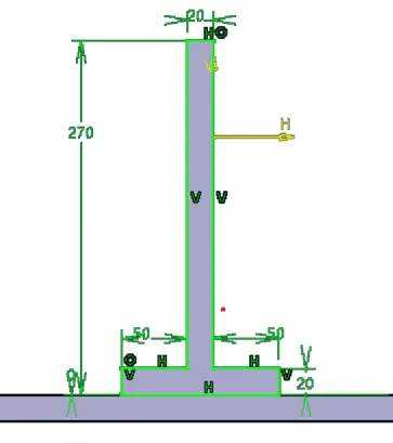
FIG RISER
Hence the second riser also having the similar steps full assembly of the REST UNIT is shown below and the second rest unit was names as P001_Z01_ST01_07_00_REST_UNIT_2
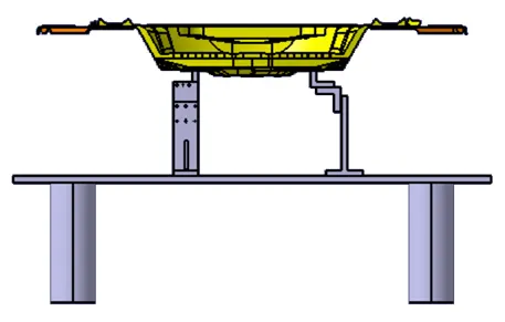
FIG FRONT VIEW OF REST UNIT
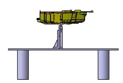
FIG SIDE VIEW OF REST UNIT
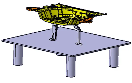
FIG REST UNIT
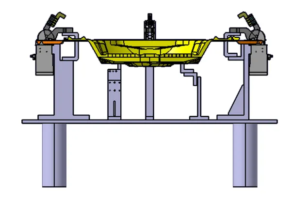
FIG POWERUNIT AND REST UNIT(FR_VIEW)
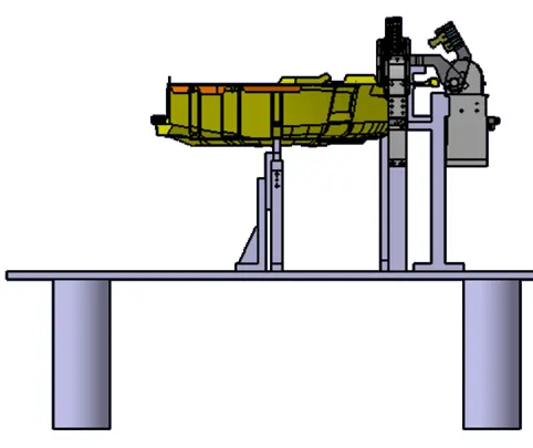
FIG POWERUNIT AND REST UNIT(SIDE_VIEW)
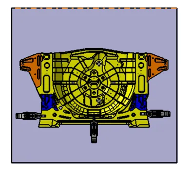
FIG POWERUNIT AND REST UNIT(TOP_VIEW)
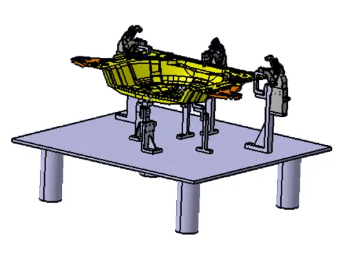
FIG POWERUNIT AND REST UNIT(ISO_VIEW)
Conclusion
Hence as per the design was named as (P001_Z01_ST01_00_00) and the 1st Power Clamp unit was named as (P001_Z01_ST01_03_00_POWER_CLAMP_UNIT.1) and second Power Clamp unit was named as (P001_Z01_ST01_04_00_POWER_CLAMP_II) and third Power Clamp unit was named as (P001_Z01_ST01_05_00_POWER_CLAMP_III)..
And Rest unit 1st and 2nd named as (P001_Z01_ST01_06_00_REST_UNIT_1),
( P001_Z01_ST01_07_00_REST_UNIT_2),
with different types of clamp units,power clamps,reisres,blades,shims,are designed using CatiaV5 Sucessfully