Week 5 - Rayleigh Taylor Instability
Aim:
To Perform the Rayleigh Taylor instability simulation for 2 different mesh sizes with the base mesh being 0.5 mm. Compare the results by showing the animations
Rayleigh taylors instability:
The Rayleigh–Taylor instability, or RT instability (after Lord Rayleigh and G. I. Taylor), is an instability of an interface between two fluids of different densities which occurs when the lighter fluid is pushing the heavier fluid
In Ansys Fluent RT Instability can be simulated by
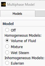
Volume fraction
mixture
wet steam
Eulerian model
The Atwood number:
The Atwood number is a dimensionless number in fluid dynamics used in the study of hydrodynamic instabilities in density-stratified flows. The Atwood number equals the ratio of the difference in mass densities to their sum.
Formula:

Here the lighter fluid is air and the heavier fluid is water
Case 1:
water(998.2 kg/m3) and air as working fluid(1.225kg/m3)
Atwood number = 0.996
Case 2:
water(998.2 kg/m3) and air as working fluid(1.225kg/m3)
Atwood number = 0.996
mesh size = 0.1 mm
Case 3:
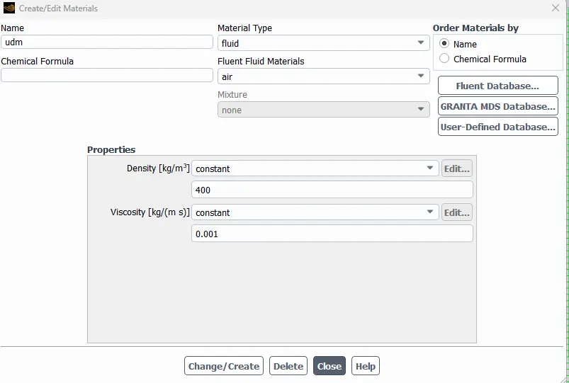
Water and user defined material(density = 400 kg/m3, viscosity = 0.001 kg/m-s)
Atwood number = 0.427
mesh size = 0.1 mm
Case1: Atwood number = 0.996- Mesh size = 0.5mm
- Create sketch
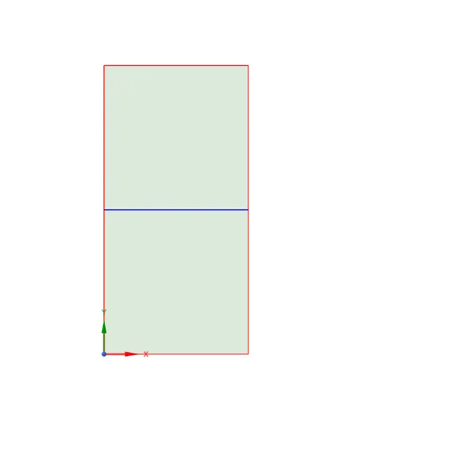
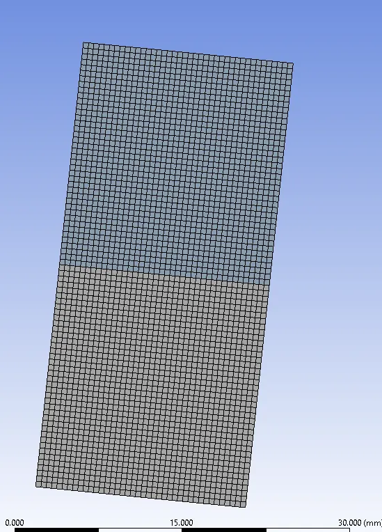
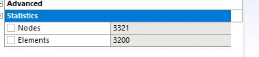
2. Mesh with length of Element size 0.5 mm
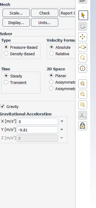
3. Set gravity
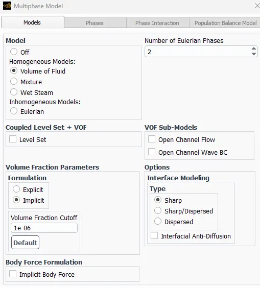
4.Use VOF model and implicit
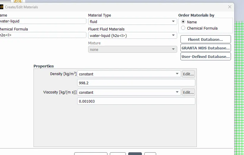
5. Add water in material
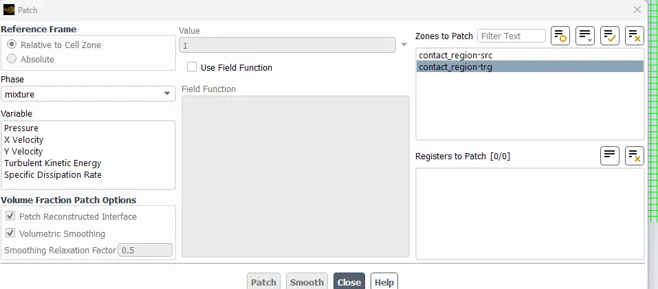
6. Patch VOF=1 water region VOF=0 in air
7. Animation video
Time step size = 0.005 s
No of timesteps = 400
Total time = 2 s
https://drive.google.com/file/d/1Au3vlzD-sTo9UYipLY_x-S28nXBRU84j/view?usp=sharing
Case-2- Atwood number = 0.996 Mesh length = 0.1 mm
1. Case 1 geometry is used
2. Change mesh length as 0.1 mm
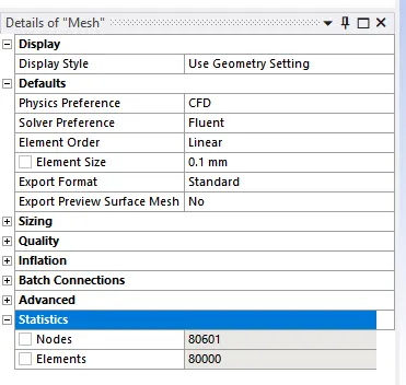
The total number of elements is 80000
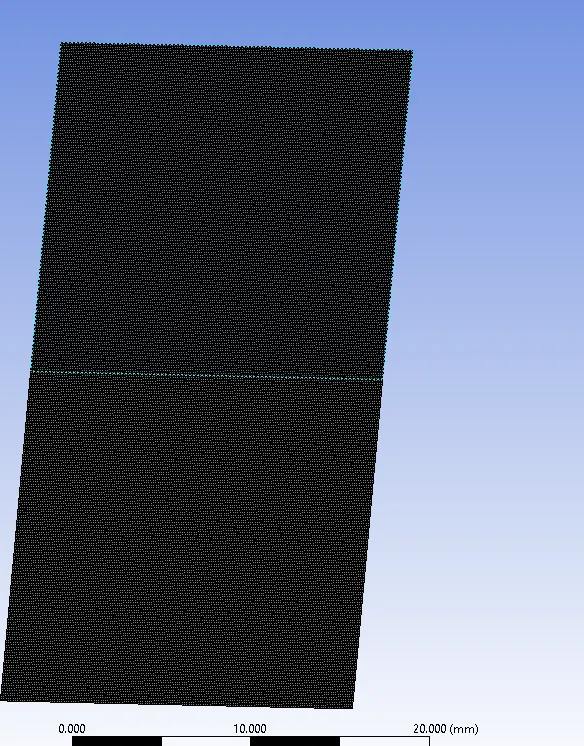
Steps 3-6 are same as in previous case
Check once again all the models and values
VOF contour after patching
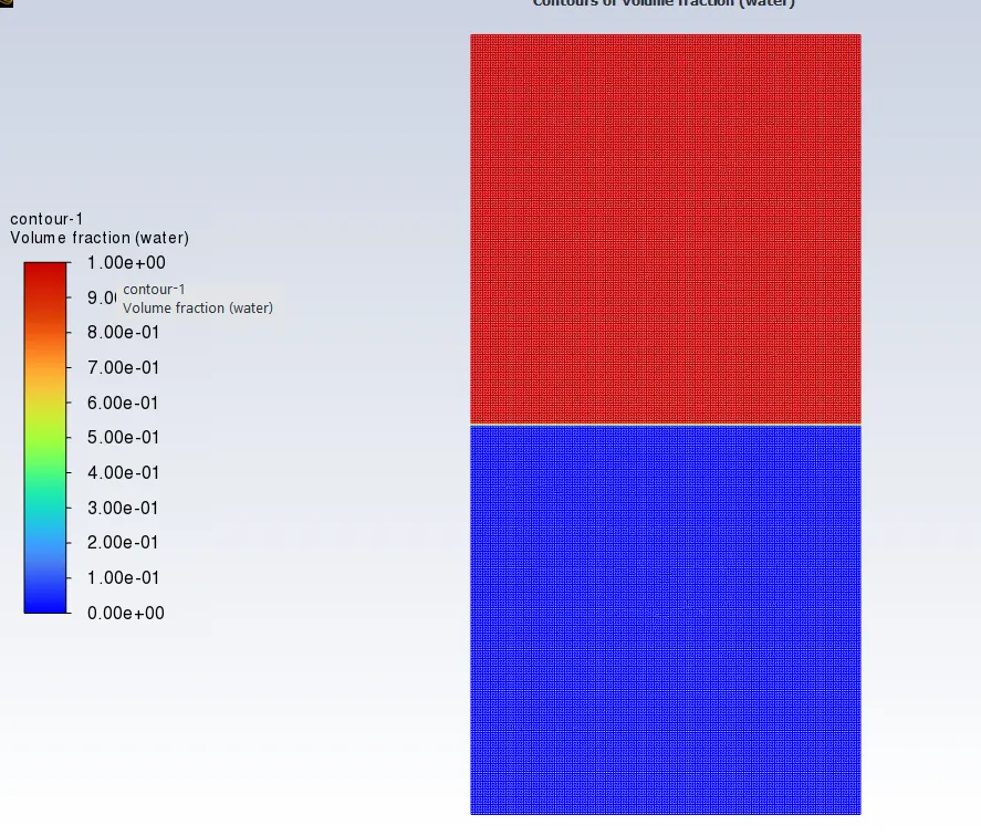
Here the time step sixe of 0.005 seconds the results are diverged
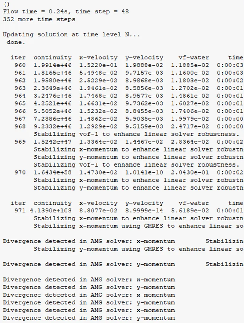
The reason for the divergence is due to that the cell size was reduced to 0.1 mm
To increase the stability of the calculation process the time step size was reduced to 0.0005 seconds. then it runs about 2000 time steps
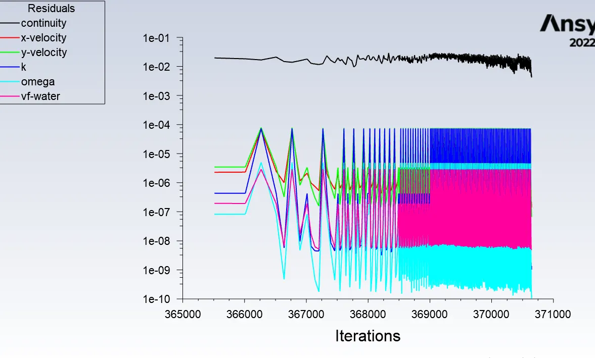
The results are realistic.
7. Animation video
https://drive.google.com/file/d/11JPf5ydJ1-162lFCRaLZKxfN57eKFND2/view?usp=drive_link
Case3: Atwood number = 0.427- Mesh size = 0.1mm (User defined material)
- Case 1 geometry is used
-
Change mesh length as 0.1 mm
3. Step 3,4 are same as case 1
5. Change the material as UDM
6. Patch VOF=1 water region VOF=0 in air
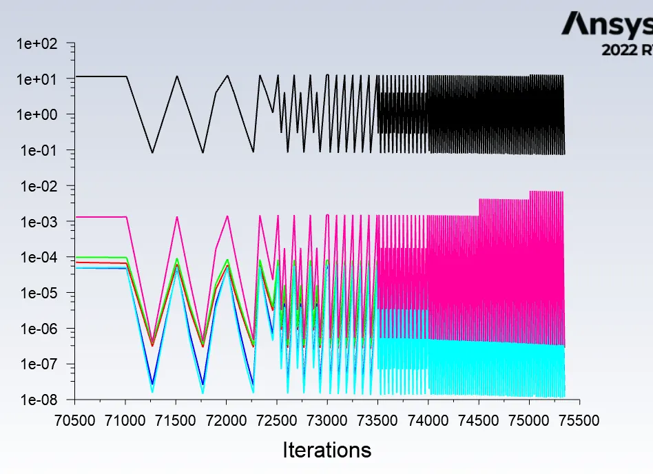
Residuals graph
7. Animation video
https://drive.google.com/file/d/1p7kEz-P0pt_W2kgAACIy9QllLel_FfJW/view?usp=sharing
Conclusion:
1. The main thing observed in this analysis is time step size.
Time step size is the important factor that affects the convergence of the results
If mesh size is decreased then the corresponding time step also decreased to get the nice pattern of flow.
Finally all the dense fluid goes down and the lighter fluid goes up. Rayleigh tailor stability can be observed here.
2. The main difference seen between water-air and water-userdefined material is, water-userdefined material taken more time to reach the saturation state. In animation video we can see that the fluid is rising slowly to the top. this is due to userdefined material in the second layer is more dense than air so it takes more time to overcome the gravitational force when comparing to the air
References:
| https://www.osti.gov/pages/servlets/purl/1841259 |