Week 5 - Rayleigh Taylor Instability
Aim and its objective:
To perform a CFD simulation of Rayleigh Taylor. To perform the Rayleigh Taylor instability simulation for 2 different mesh sizes with the base mesh being 0.5 mm and to compare the results by showing the animations.
Procedure:
All cases are followed the unsteady flow (Transient condition which is based on time step size in seconds) of two phases of the flow.
Case 1- Base mesh
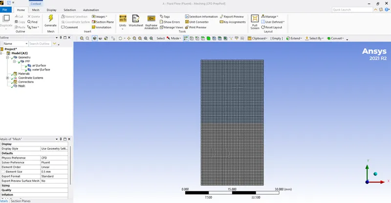
Basemesh with an elemental size of 0.5mm and has the fluid materials air and water.
Geometry in space claim:
- Choose Fluent from the workbench setup, and edit SpaceClaim to create geometry.
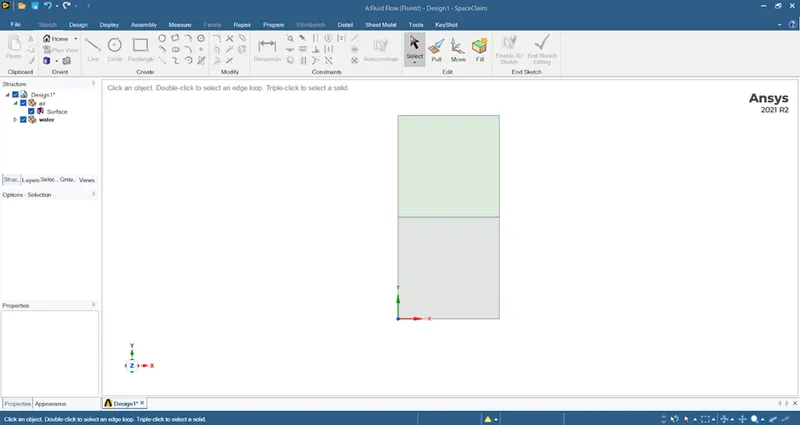
- Choose the XY plane to sketch 2Dgeometry, create a square of 20mm, and select the pull tool to make it a surface of that.
- Move the geometry to a new component and rename it as Air.
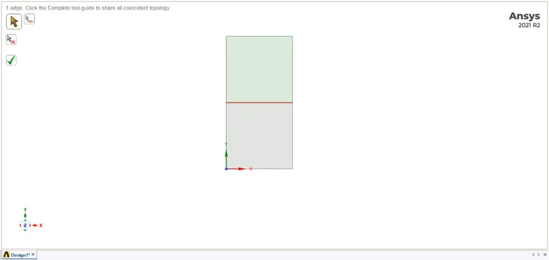
- Now create new geometry under the main design as water and create a square of 20mm right on top of the air square which creates an interface between the 2 boxes.
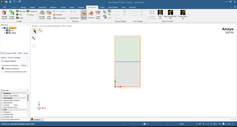
- Select the entire geometry for share prep under the workbench and select share so that the interface can face information and conformal meshing can be achieved between the 2 phases.
Surface component of air and water
Interface region:
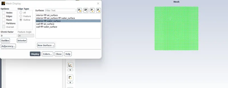
Mesh (Base mesh):
After creating the geometry open the mesh and generate the mesh with an elemental size 0f 0.5mm. After updating the mesh open the fluent, here we set the general setting to pressure-based solver with transient time simulation because we have to see the interface collapse with the time. And select the gravity with a y coordinate -9.81m/s^s.
Parameters:
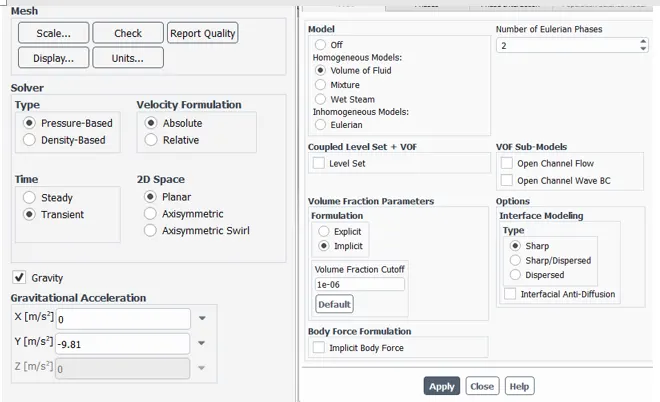
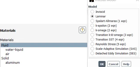
Under physics Use laminar in viscous flow and in the multiphase select volume of the fluid model because here we designed to find out the position of the interface between the two or more immiscible fluids.
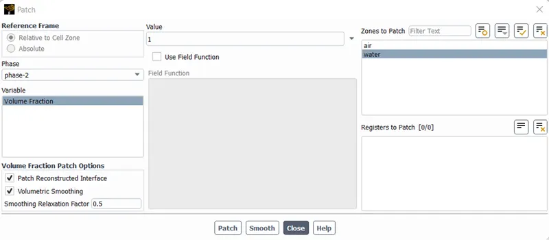
Initialize using standard initialization, then use the patch option to give the alpha value for water as 1 and 0 for air.
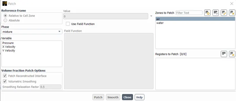
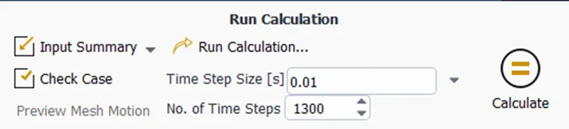
Run calculation:
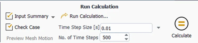
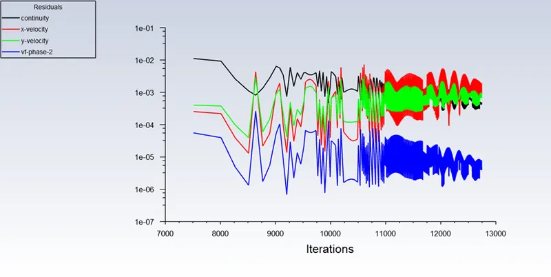
Scaled residuals plots:
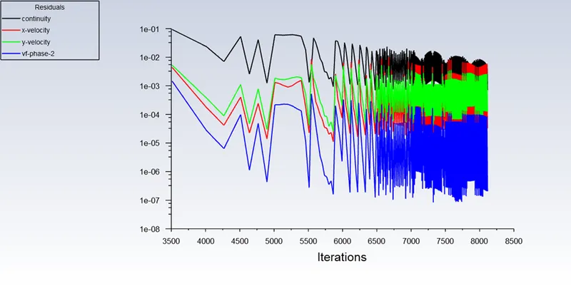
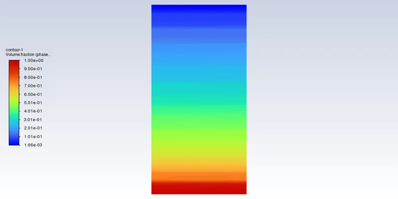
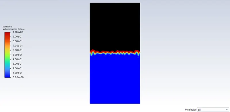
Initial flow disturbance of two phases:
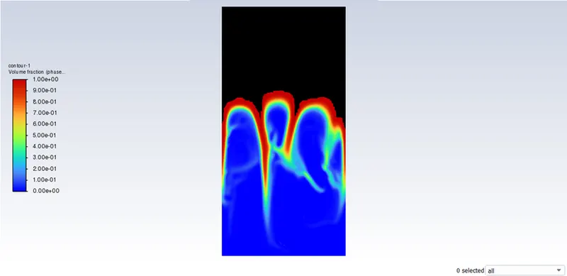
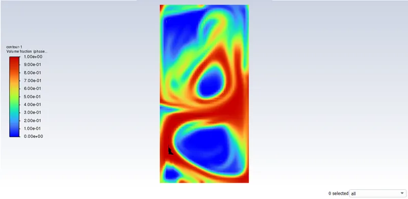
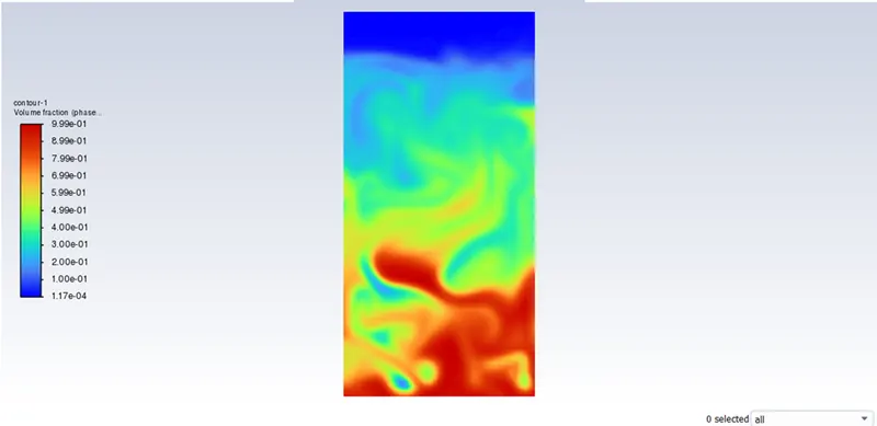
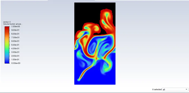
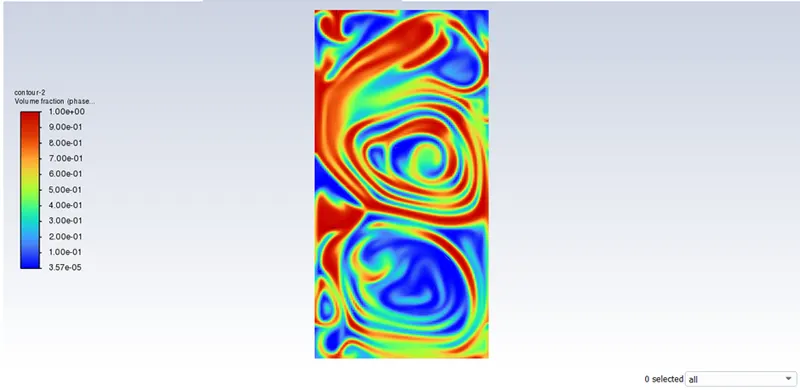
Volume fraction contour in phases
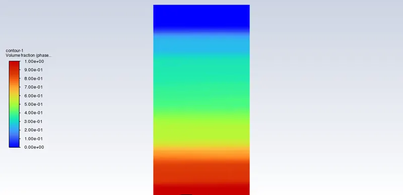
Case 2- Refined mesh
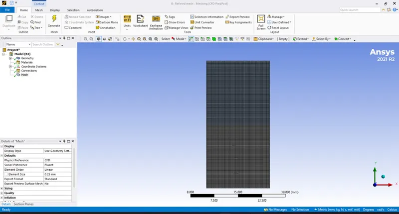
Mesh (Refined mesh):
Refined mesh with an elemental size of 0.25mm and having the fluid materials air and water.
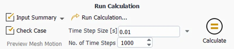
Run calculation:
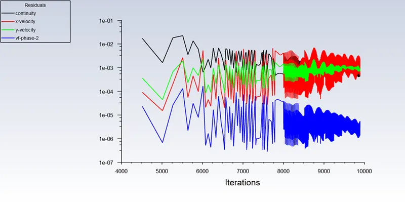
Scaled residuals plots:
Initial flow disturbance of two phases:
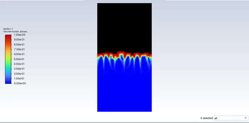
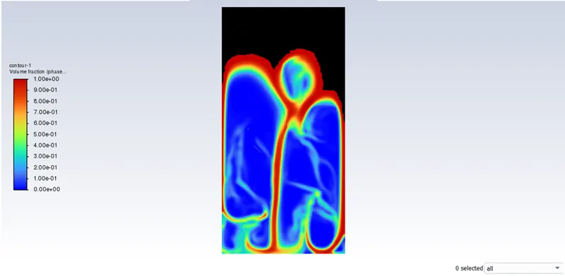
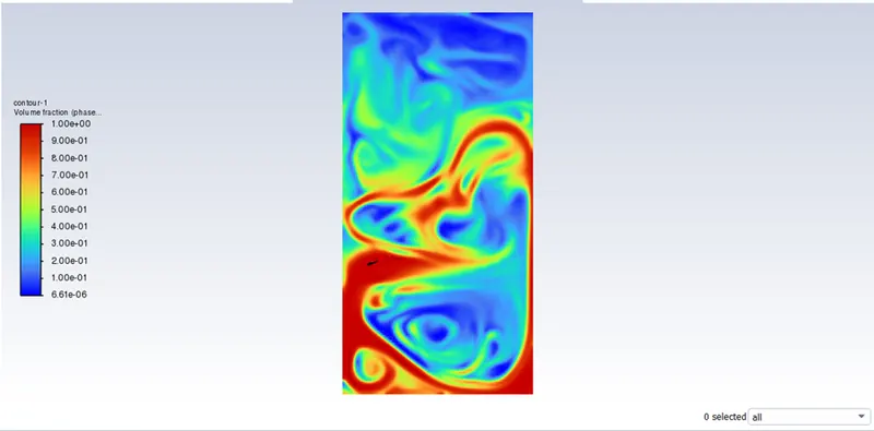
Volume fraction contour in phases
Case 3- Fined mesh
Mesh (Fined mesh):
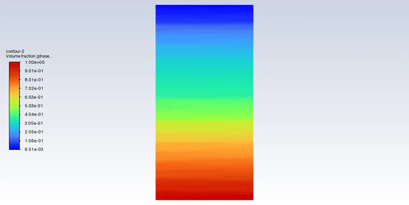
Fiined mesh with an elemental size of 0.25 mm and having the water and user-defined material as,
Run calculation:
Scaled residuals plots:
Initial flow disturbance of two phases:
Volume fraction contour in phases:
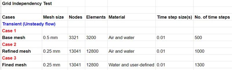
Grid independency test:
This is the Grid dependency test, where, analysis begins with a coarse mesh and is refined to a finer mesh for each run until the results do not change significantly and depend on the grid size anymore. As the grid or mesh size approaches zero, the approximate solution is almost equal to the actual solution.
Atwood number:
The Atwood number (A) is a dimensionless number in fluid dynamics used in the study of hydrodynamic instabilities in density-stratified flows. It is a dimensionless density ratio defined as

where,
 = density of the heavier fluid
 = density of the lighter fluid
Case 1 & 2: For fluid materials air and water
ρ1">ρ1=density of water=998.2kg/m^3
ρ2">ρ2=density of air=1.225kg/m^3
A= 998.2-1.225 / 998.2+1.225
A=0.9975
Case 3: For fluid materials user-defined and water
ρ1">ρ1=density of water=998.2kg/m^3
ρ2">ρ2=density of user defined=400kg/m^3
A= 998.2-400 / 998.2+400
A=0.427
The difference in the fluid densities divided by their sum is defined as the Atwood number A.
For A close to 0, RT instability flows take the form of symmetric "fingers" of fluid; for A close to 1, the much lighter fluid "below" the heavier fluid takes the form of larger bubble-like plumes.
Conclusion:
- From the aforementioned examples, we can see that a finer mesh catches instability better than a coarse mesh, but that the heavier fluid takes longer to settle than a fine mesh. Despite the lengthy computing time, the results are more accurate.
- The transient technique is favored over the steady-state approach because the simulation must capture instabilities that change in an unanticipated way over time.
- The CFD simulation as it is observed is validated by the Atwood no. The creation of bubbles occurs when water and air mix, but not in the other situation.