Week 5: Project : Centrifugal pump simulation
CENTRIFUGAL PUMP SIMULATION
AIM:
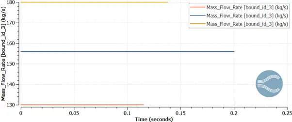
To run the simulation process for centrifugal pump for outflows of three different mass flow rate.
- Mass flow rate- 130 kg/s
- Mass flow rate- 156 kg/s
- Mass flow rate- 180 kg/s
OBJECTIVE:
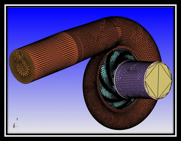
Centrifugal pumps are the most popular and commonly used type of pump for the transfer of fluids. In simple words, it is a pump that uses the rotating impeller to move water or other fluids by using centrifugal force. These are the undisputed pump choice especially for delivering liquid from one location to another in numerous industries including agriculture, municipal (water and wastewater plant), industrial, power generation plants, petroleum, mining, chemical, pharmaceutical and many others.
Centrifugal pumps are very useful since they can generally handle large quantities of fluids, provide very high flow rates (which may vary with the changes in the Total Dynamic Head of the particular piping system) and have the ability to adjust their flow rates over a wide range.
WORKING OF CENTRIFUGAL PUMP
Let us understand in detail, how a Centrifugal pump works. Centrifugal pumps are used to induce flow or raise a liquid from a low level to a high level. These pumps work on a very simple mechanism. A centrifugal pump converts rotational energy, often from a motor, to energy in a moving fluid.
The two main parts that are responsible for the conversion of energy are the impeller and the casing. The impeller is the rotating part of the pump and the casing is the airtight passage which surrounds the impeller. In a centrifugal pump, fluid enters into the casing, falls on the impeller blades at the eye of the impeller, and is whirled tangentially and radially outward until it leaves the impeller into the diffuser part of the casing. While passing through the impeller, the fluid is gaining both velocity and pressure.
CASE SETUP:
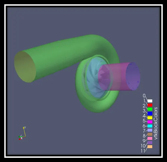
Here in this simulation process, the liquid simulation has been chosen and H2O is selected as the liquid flow. In run parameters, transient mode is selected for solver the simulation mode is full hydrodynamic and the liquid flow solver will be incompressible. In Navier Strokes solver, density based is selected.
In simulation time parameters:
End time: 0.2 sec
Initial time step: 1e-09 sec
Min time step: 1e-09 sec
Max time step: 1.0 sec
In boundary condition:
Inlet (BOUNDARY ID- 2) - Pressure- 101325 Pa
- Velocity- Zero Gradient
- Temperature- 300 K
Outlet (BOUNDARY ID-3) – Pressure- Zero Gradient
- Velocity- 130 kg/s
156 kg/s
180 kg/s
- Temperature- 300 K
Volute- Wall motion type- Stationary
- Surface movement- FIXED
- Temperature- Zero Gradient
Intake runner- Wall motion type- Stationary
- Surface movement- FIXED
- Temperature- Law of wall
- 300 K
Shroud- Wall motion type- Stationary
- Surface movement- FIXED
- Temperature- Law of wall
- 300 K
Impeller- Wall motion type- Rotating
- Surface movement- MOVING
- 12000.0 deg/sec
- Temperature- 300 K
In physical mode:
Turbulence model- RNG k-ε
In grid control mode:
Base grid: dx- 0.012m
dy- 0.012m
dz- 0.012m
Fixed embedding- Entry type- Boundary
- Boundary ID- Impeller
- Mode- PERMANENT
- Scale- 2
- Embed layers- 1
Surface with edges:
Surface with edges: https://www.youtube.com/watch?v=7bkhqH_ClEA
Pressure contours:
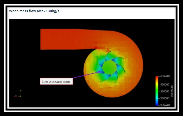
mass flow rate- 130 kg/s
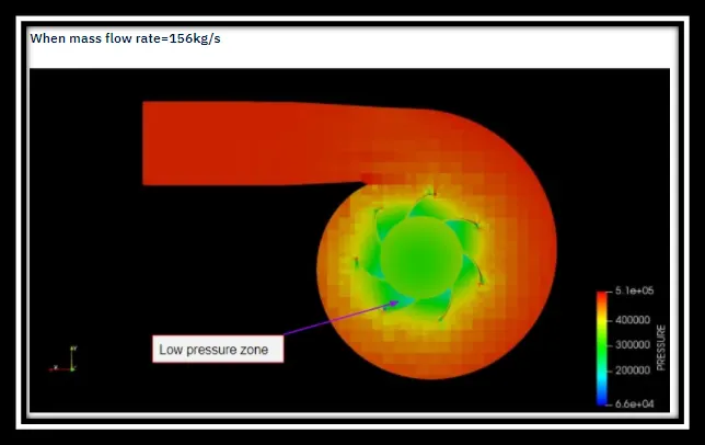
mass flow rate- 156 kg/s
mass flow rate- 180 kg/s
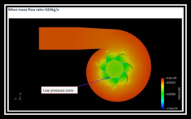
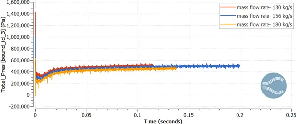
Here, the fluid comes inside the pump through the inlet and the pressure at the impeller area is quite low. When it spreads the fluid due to its inertia it flows centrifugally and then reaches the outlet. At this point, the pressure gradually increases and reaches at a particular level.
Velocity contours:
Velocity contours: https://www.youtube.com/watch?v=ytdp4Sv049A
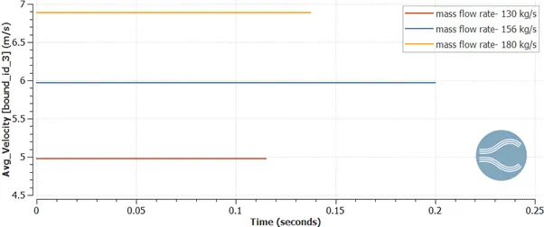
Here, at the impeller area the velocity is pretty much high due to pressure reduction and that velocity gradually decreases when it comes to the outlet port. At the bottom part of outlet port the velocity just comes to zero since there is no flow.
Mass flow rate:
Inlet:
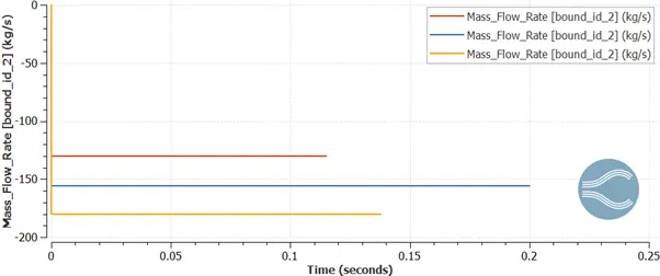
Outlet:
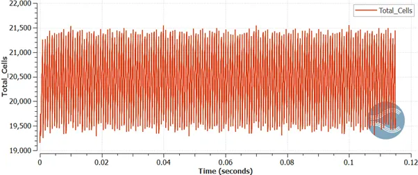
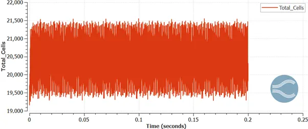
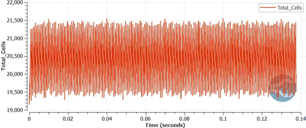
Total cell count:
mass flow rate- 130 kg/s
mass flow rate- 156 kg/s
mass flow rate- 180 kg/s
CONCLUSION:
So, the simulation process for centrifugal pump is done for three different mass flow rate and from the results has been shown.