Project : Transient simulation of flow over a throttle body
TRANSIENT SIMULATION OF FLOW OVER A THROTTLE BODY
AIM:
To simulate the transient flow over a throttle body using converge and analyse the results when the valve moves from 0° to 25° position.
OBJECTIVES:
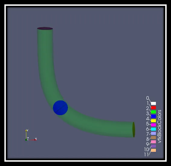
A control valve is a power operated device capable of modulating the flow at varying degrees between minimal flow and full capacity in response to a signal from the controlling system. Valves are available with a wide variety of valve bodies in various style, materials, connections and sizes. Here the simulation is performed by butterfly valve.
Butterfly valve consists of a disc attached to a shaft with bearing used to facilitate rotation. The flow capacity is relatively high and the pressure drop across the valve is relatively low.
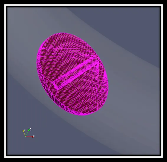
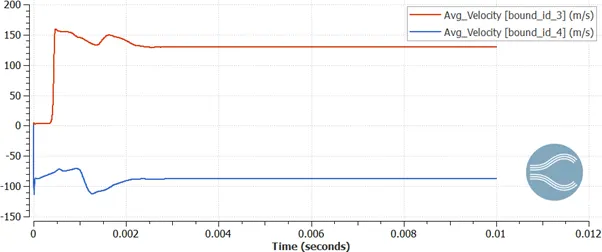
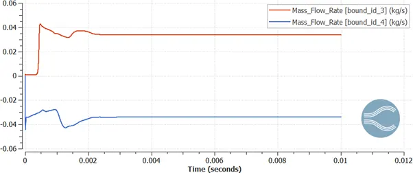
In this case, when the simulation time starts the valve remains at 0° position. After 2milli-sec, the valve rotates at 25° position, which blocks the half of the flow and it remains in that position for the rest of the simulation period.
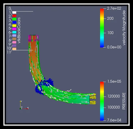
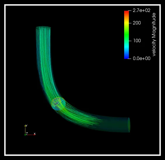
From the below figure, you can see that when the valve is at 25° position the vector plots gets blocked by the valve and diverted to the side of it.
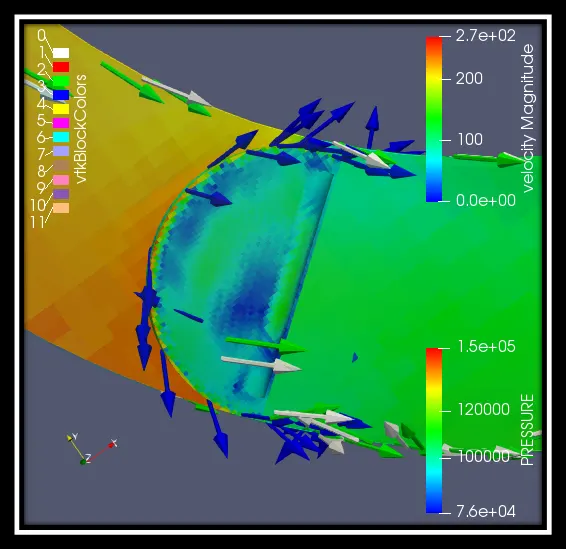
Throttle movement (surface with edges): https://www.youtube.com/watch?v=fAolkyjsu9A&feature=youtu.be
CASE SETUP:
Here, air is selected for the flow simulation. In the run parameters the solver is selected as transient and the simulation mode will be in full hydrodynamic. Since we have selected in transient flow, the time parameters has changed to seconds instead of cycles.
In simulation time parameters:
End time: 0.01sec
Initial time step: 1e-09sec
Min time step: 1e-09sec
Max time step: 1.0sec
In boundary condition:
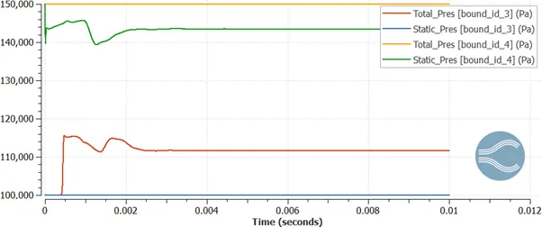
Inlet (Boundary ID-4): Pressure- 150000Pa
Velocity- Zero Gradient
Temperature- 300K
Outlet (Boundary ID-3): Pressure- 100000Pa
Velocity- Zero Gradient
Temperature- 300K
Elbow wall: Wall motion type- Stationary
Surface movement- Fixed
Temperature- Zero Gradient
Throttle valve (0° to 25° position): Wall motion type- Rotating
Surface movement- Moving
Temperature- Zero Gradient
|
SEC |
ANGLE |
|
0 |
0 |
|
0.002 |
25 |
In grid control
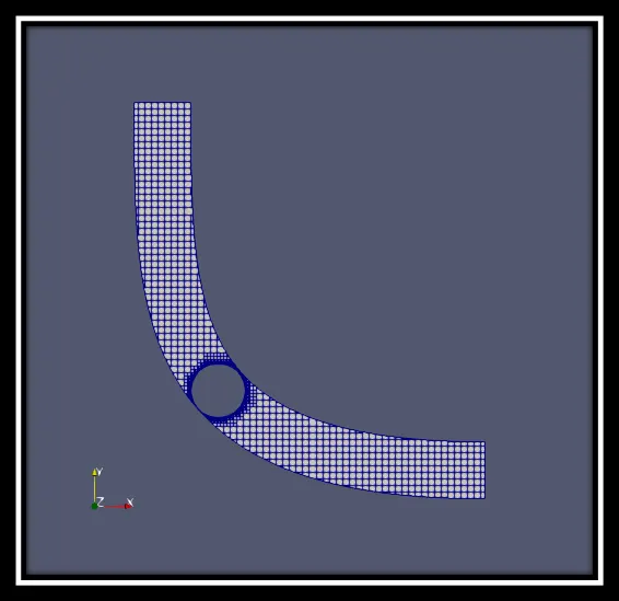
Base grid: 0.002m
Fixed Embedding: Mode- Permanent
Scale- 3
Embed layers- 2
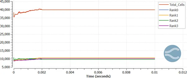
Under run parameters, the simulation mode is selected as full hydrodynamic, and in this case it makes the process relatively slow. It took me around 6 n half hours to complete the process. In order to avoid this, the simulation mode can be selected as no hydrodynamic.
Pressure:
Pressure contours: https://www.youtube.com/watch?v=AHFjz3JLP5k&feature=youtu.be
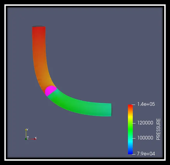
The Pressure ranges from 1.5bar to 1.0bar, and when the flow enters it moves towards the throttle valve which rotates at 2millisec and gets interacted with the valve and then reaches the steady state for the remaining simulation. The high pressure of 1.4bar can be seen at the throttle valve area.
Velocity:
Velocity contours: https://www.youtube.com/watch?v=AVnbNB0aqOQ&feature=youtu.be
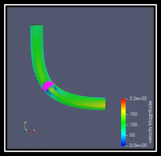
From the above figure, you can notice that the velocity of the flow is around 100 to 150 m/s. At the throttle point, there has been a drop in the velocity since the throttle rotates at 25°.
Streamline tracer:
Streamline tracer contours: https://www.youtube.com/watch?v=597no3wljis&feature=youtu.be
Mass flow rate:
Total cell count:
CONCLUSION:
So, the transient flow simulation process over the throttle body is done and the above result shows that how the velocity reduced and how the pressure rises very high when the throttle valve rotates at 25°. We can also experiment it further by rotating at different angles to get different kind of result.