Week - 5 - Modelling Spotwelds
Week - 5 - Modelling Spotwelds
Aim :- Run a crash box simulation using beam spotweld and solid hex spotweld and compare the results (axial and shear forces)
Problem Statement :- In this assignment, you will model spotwelds for the given assembly of parts and run a crash test similar to the one in assignment 4. Details about spotweld location is in the image below. The yellow line signifies the spotweld directions. You need to use 3-7 spotwelds along this line, in a symmetric manner, before running the simulation.
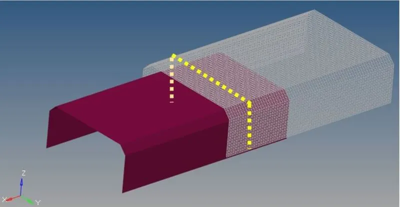
The spotwelds should be modeled using beam elements and solid elements separately. While using solid elements, one spotweld should have one solid element. The axial and shear force should be compared among beam and solid elements. The same material card using *MAT_SPOTWELD should be used for both beam and solid elements. You can use steel material data for *MAT_SPOTWELD cards and calibrate the failure data according to your results. The best simulation should have a failure at half of the termination time.
Procedure :-
- Open LS-Dyna Project Manager>>Start LS Prepost>>Import the given model.
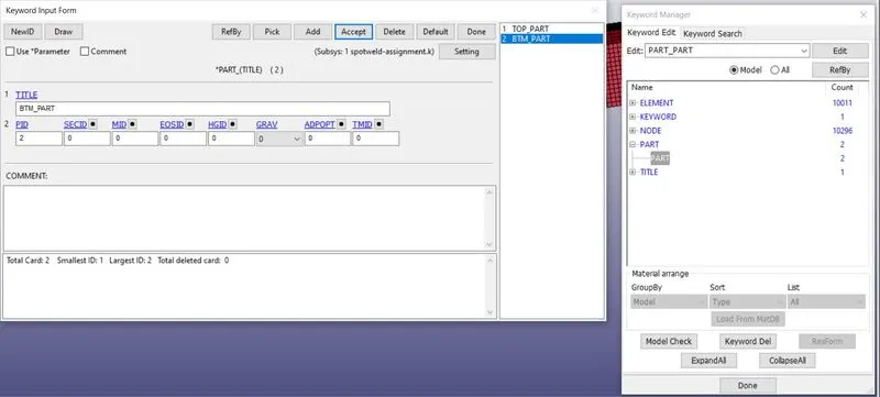
- Open Keyword Manager>>Part>>Define the parts with proper name. This is shown in the figure below.
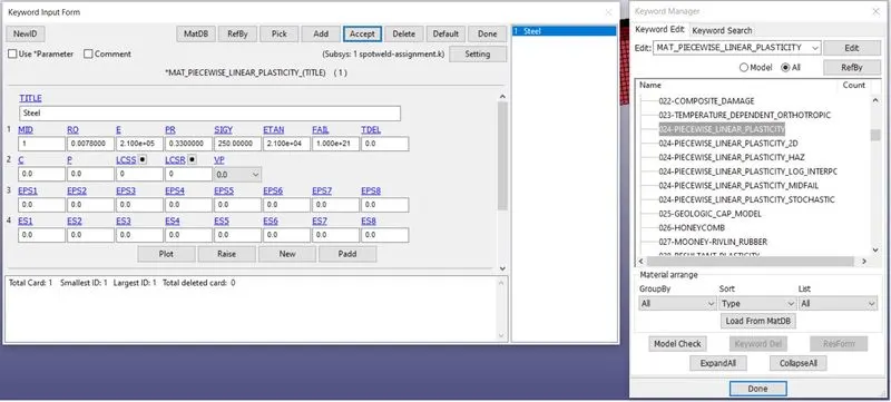
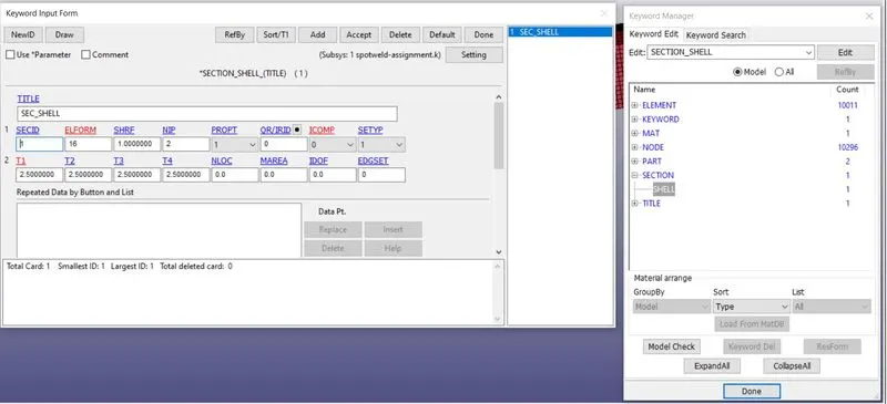
- Define the material as steel for the top and bottom parts and create a shell section as shown in the figure below. Assign the corresponding properties to the part card.
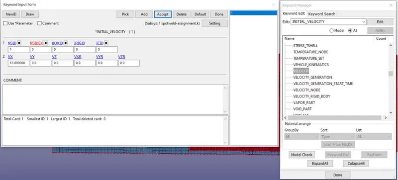
- In this model the crashbox assembly is made to hit on the rigid wall at an velocity of 13.88 mm/ms. Initial velocity card is used to apply velocity for crashing assembly in the direction of impact as shown in image below.
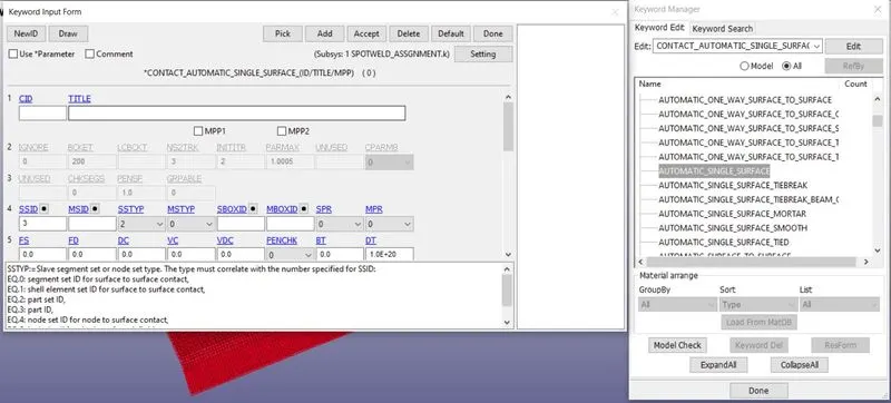
- This card can be used to specify contacts that could occur between the two shell components or the elements within. This can be achieved by creating a set_parts which contains both the top and bottom shell componets and assigning it to SSIDin the card while the SSTYPis set to 2.
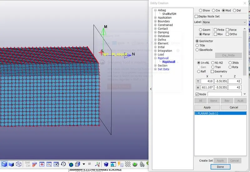
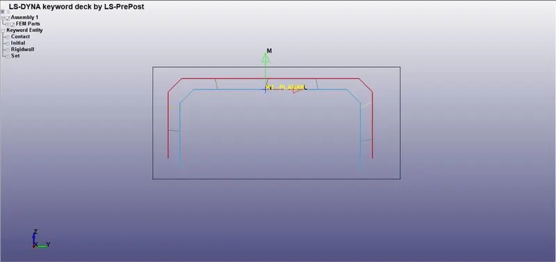
- Now create a rigid wall to create an impact of the bracket against the wall. The wall position is shown in the figure below.
- Go to Element and Mesh>>Element Creation>>Select Beam type>>Pick the nodes between two parts and create the spotwelds with new part ID for all the welds. This is shown in the figure below.
- Material & section creation for a beam elements & solid elements:-
-After the creation of material & section for part, now create the material & section for the beam element.
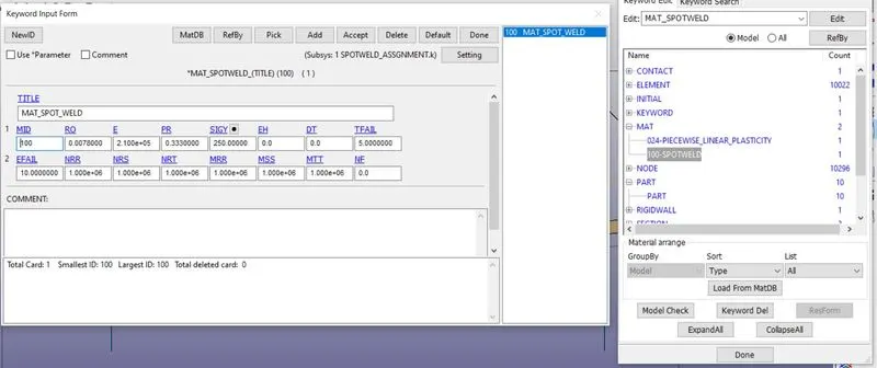
-Here, we use MAT_100 card for assign the material.
-Another thing, we use time base failure. It means fail the beam at 5 ms.
For Beam elements & solid elements:-
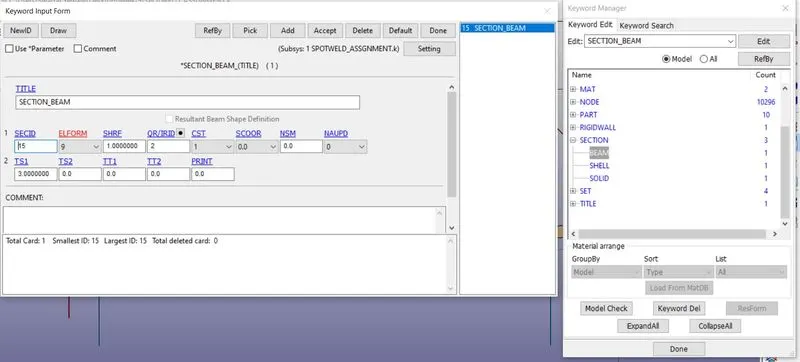
-Here, we use section_beam card for the assign the section for beam.
-Provide the variuos values:-
ELFORM=9 (Element formulation)
CST=1
TS1=3 (Thickness)
*For Beam elements:-
*For solid elements:-
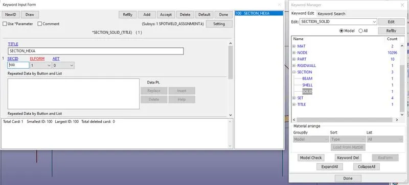
-Here, provide ELFORM=1
-After the creation of material & section card for the beam element, now assign that for every beam elements and solid elements.
9.Binary_D3plot & ASCII_option define:-
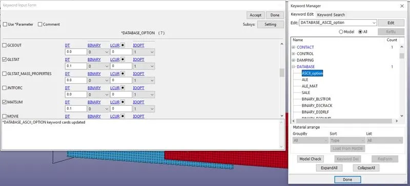
Now, the following output data is generated by using the *DATABASE card with a time step of 0.1ms are assigned for generating output data.
DATABASE_BINARY_D3PLOT --> Used to find out the animation of the process,
DATABASE_ASCII_NODOUT --> To find the Nodal motions,
DATABASE_ASCII_ELOUT --> To find the element data,
DATABASE_ASCII_GLSTAT --> To find the global statistics and energies,
DATABASE_ASCII_MATSUM --> To find the material energies,
DATABASE_ASCII_RCFORC --> To find the Resultant contact interface forces,
DATABASE_ASCII_SLEOUT --> To find the Contact interface energies
DATABASE_ASCII_SECFORC --> To find the Cross-section forces data
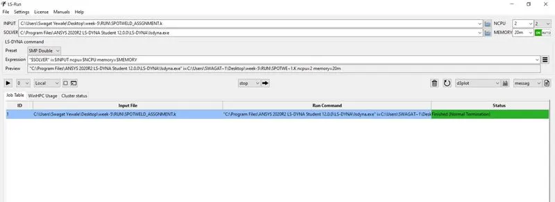
- After that model is ready for the simulation. The keyword file (.k) can be edited in notepad++ so that the comparison study can be done for the spotwelds which is created by Beam elements and Solid elements . Save the keyword for both files and open in the LS-DYNA manager which solves the problem with normal termination.
Output results :-
- The simulation results are shown in the figures below.
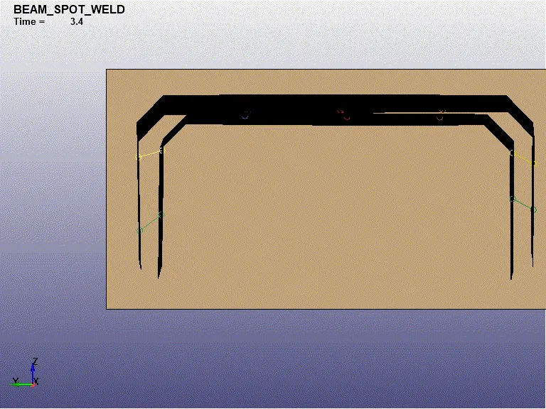
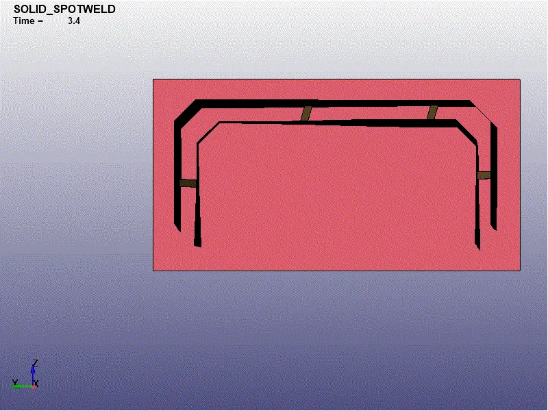
From the animation it can be inferred that the welds fail at exactly 5 ms int a total run time of 10 ms. The rebound is slower in the case of hexa spotweld. This is because the inertia offered by the hexa welds is higher when compared to beam elements. At 5 ms after the weld failure, the rebound happens in the lower bracket due to weld failure.
- The Von-Mises contours obtained for both the cases is shown below.
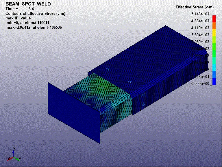
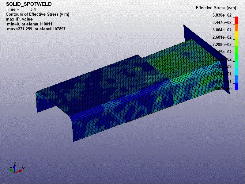
From the above Von-Mises stress contour it is clear that the stress concentration around the weld regions is significant in both the cases. After the weld failure the stress is distributed over the brackets.
- The effective plastic strain contours are shown in the figures below
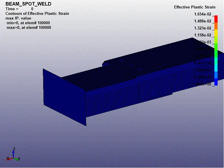
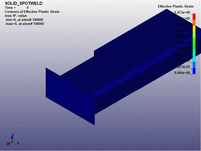
From the effective plastic strain contours it can be inferred that the strain is higher for case 2 with a value of 1.27mm and for case 1 the peak value obtained is 0.01654.
- The energy plots obtained are shown in the figures below.
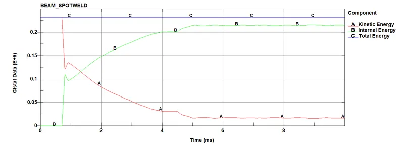
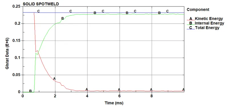
From the energy plots, At around 0.8 ms the impact against the wall happens. This causes reduction of kientic energy associated with increase in internal energy. There is a bump observed in the intersection region of the energies. This is due to inertia effect of the brackets.
- The spotwelds axial forces are shown in the figures below.
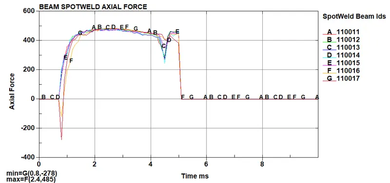
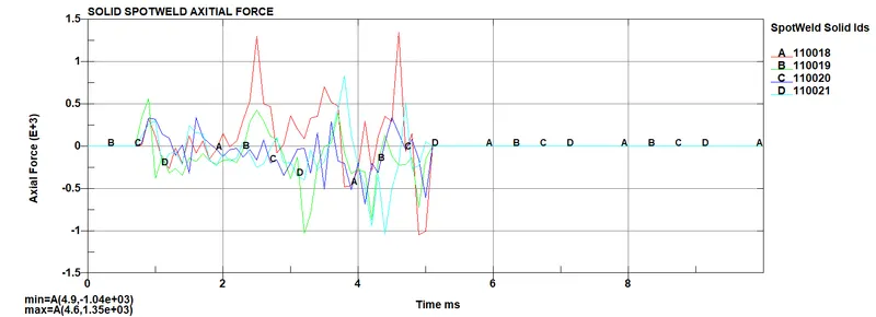
Due to higher stiffness, the axial force is higher for hexa elements in comparison with beam elements as inferred from the plot.
- The shear forces for the beam elements are shown in the figures below
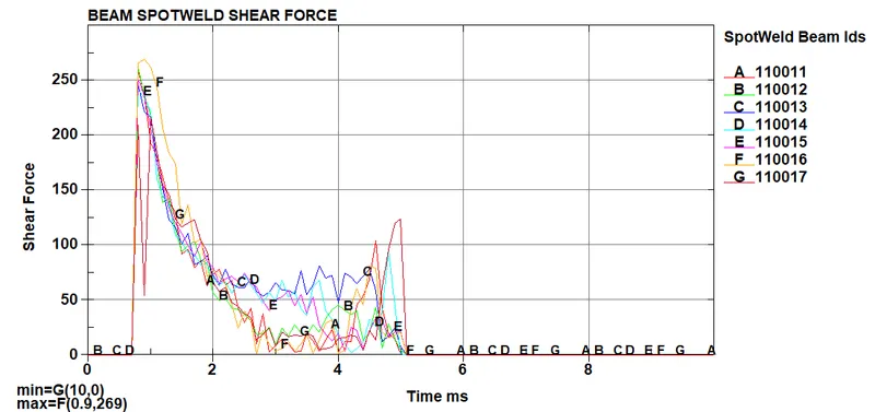
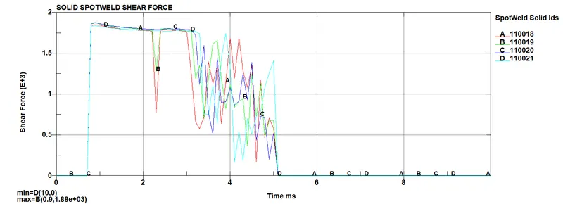
From the above plots, the shear force obtained is higher for hexa elements with a value of 1880 N.
- The resultant forces are shown in the figures below.
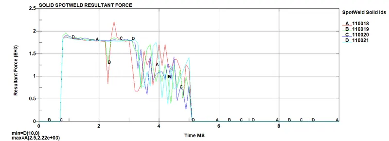
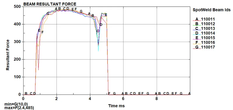
The maximum resultant value of force obtained for beam and hexa elements are 485 N and 2220 N respectively.
CONCLUSION:
The case setup was done as per the objective and the corresponding output requests are obtained. The two cases were discussed and the plots and results were compared accordingly as given in the problem statement.