Modelling Spotwelds LSDYNA
AIM
To model the spot weld for the given assembly parts using beam and solid elements separately. Also, perform the crash analysis for the same and compare the output results of the beam and solid elements.
SPOT WELDING THEORY
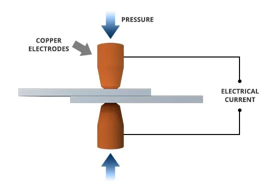
A form of resistance welding, spot welding is one of the oldest welding processes whereby two or more sheets of metal are welded together without the use of any filler material.
The process involves applying pressure and heat to the weld area using shaped alloy copper electrodes which convey an electrical current through the weld pieces. The material melts, fusing the parts together at which point the current is turned off, pressure from the electrodes is maintained and the molten “nugget” solidifies to form the joint.
The welding heat is generated by the electric current, which is transferred to the workpiece through copper alloy electrodes. Copper is used for the electrodes as it has a high thermal conductivity and low electrical resistance compared to most other metals, ensuring that the heat is generated preferentially in the work pieces rather than the electrodes.
The amount of heat depends on the thermal conductivity and electrical resistance of the metal as well as the amount of time the current is applied. This heat can be expressed by the equation:
Q = I2Rt
In this equation “Q” is heat energy, “I” is current, “R” is electrical resistance and “t” is the time for which the current is applied.
MODELLING OF SPOT WELD USING BEAM ELEMENTS:
Here steel is used for material consideration.
1. Import the keyword file of the assembled component.
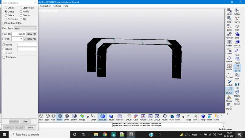
The above images represents how to create the beam elements and created beams
Element tools>element edit>create>select type>beam>uncheck the third node>select the two nodes of the assembled components. Repeat the same procedure for rest of the elements.
RIGID WALL
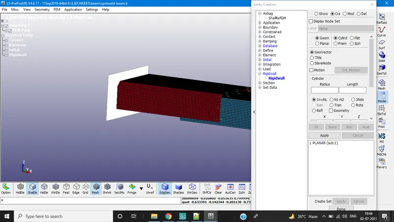
Rigidwall created by create entity>rigidwall >create>planar>select 3 nodes>translate by 15
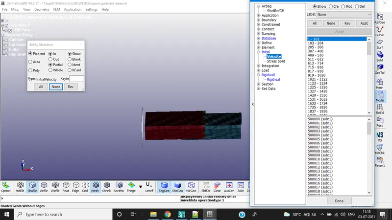
INITIAL VELOCITY
Initial Velocity is applied for all the node in the negative x-axis
For the component 10mm/ms is applied
MATERIAL CARD
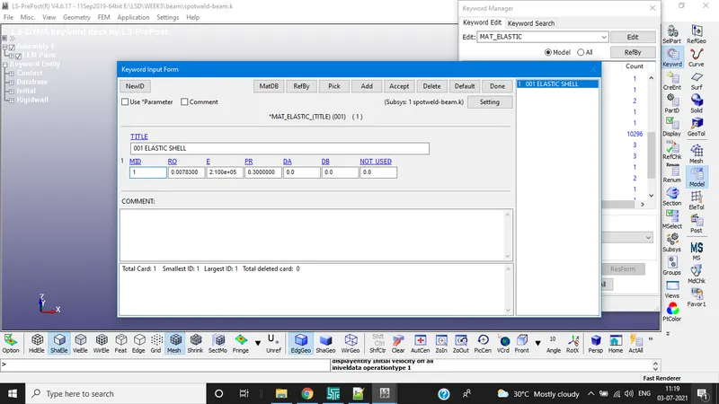
For shell elements MAT(001) Elastic is applied
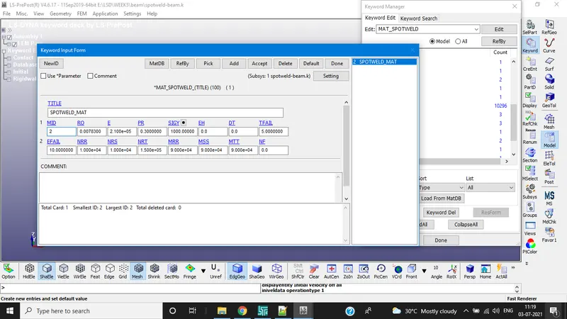
For Spotweld beam elements MAT(100) spot weld is applied
For both steel material properties are used.
And also assign values in spot weld mat card accordingly for example TFAIL, NRR,NRS,NRT,MRR, MSS
SECTION CARD FOR BEAM AND SHELL
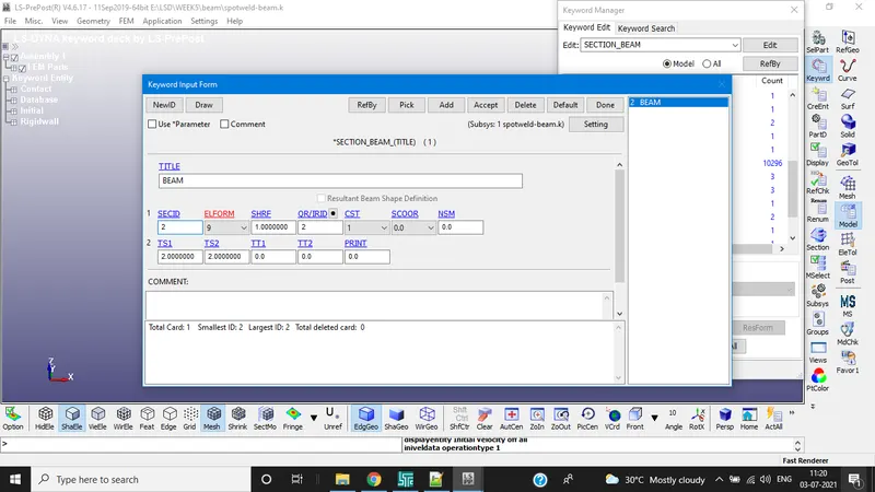
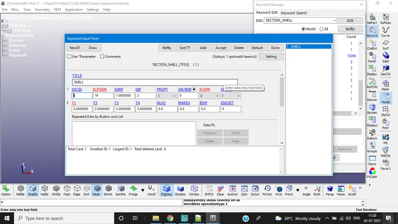
Element formulation is applied according to the beam elements.
DATABASE AND CONTROL TERMINATION:
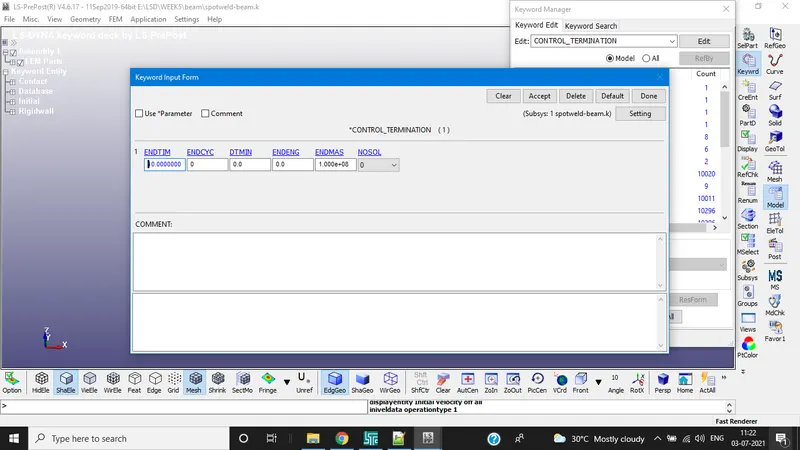
ASCII outputs are selected by requirements
For given model GLSTAT, NODOUT,SWFORC,ELOUT are considered for the simulation results.
SOLID HEXA ELEMENTS:
Solid elements are created by Element Tools>Element edit>create>select hexa> click the 8 nodes (4 on top and 4 on bottom) to create hexa solid elements. Repeat the same procedure for remaining elements.
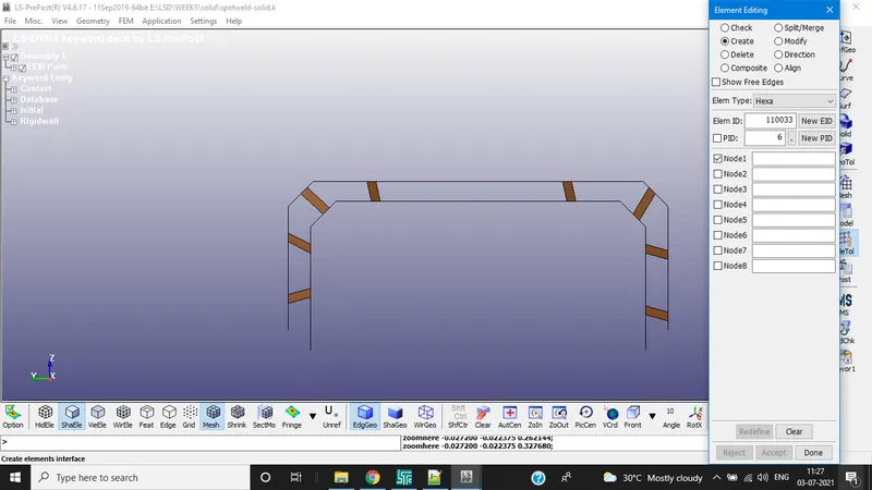
Except for the creating spotweld elements rest of the steps are same for the simulation for example Material selection,control termination,section elements, etc,.
SIMULATION RESULTS FOR BOTH BEAM AND SOLID ELEMENTS:
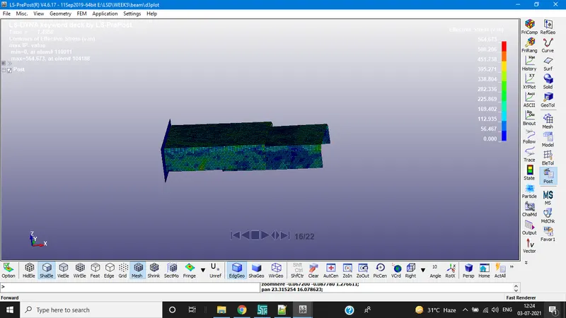
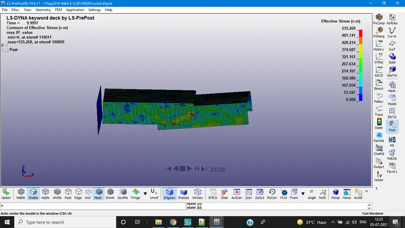
VON-MISES STRESS FOR SOLID
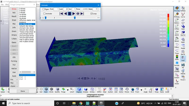
VON-MISES STRESS FOR BEAM
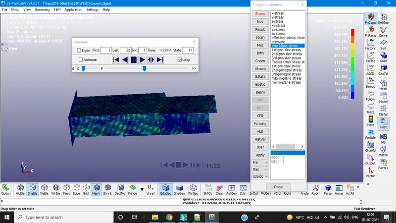
If you observe stress alues of both spotweld types there is not much difference during the point of contact to rigid wall
Von-Mises stress value at 4.9994ms for solid - 815.675Mpa
Von-mises stress value at 4.9994ms for beam - 829.70Mpa
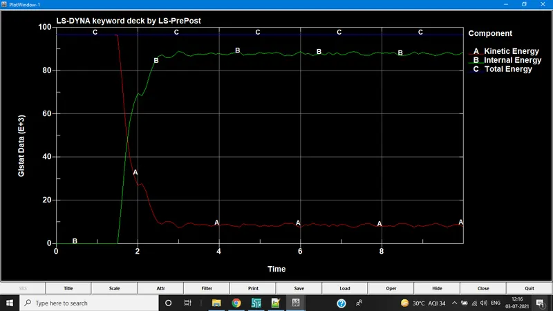
GLSTAT FOR SOLID
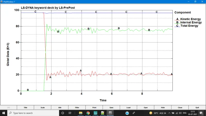
GLSTAT FOR BEAM
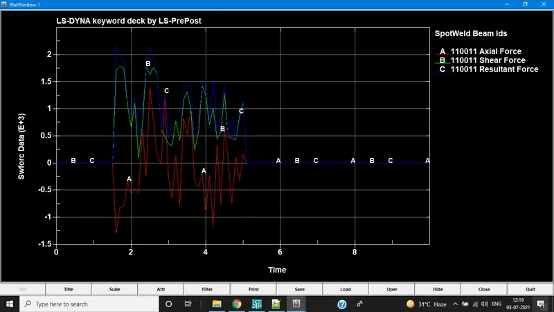
SWFORC FOR BEAM
Below graph represents only for the particular elements
SWFORC FOR SOLID
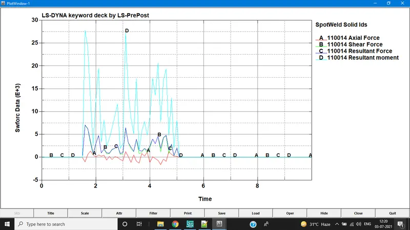
RESULT:
SOLID
BEAM