Week - 5 - Modelling Spotwelds
Objective:
To model the spot-weld for the given assembly parts using beam and solid elements separately. Also, perform the crash analysis for the same and compare the output results of the beam and solid spot-welds.
Procedure:
Case setup & Execution:
1. Importing the model:
- Open the keyword file in spotweld-assignment.k LS PREPOST.
- The file consists only of nodes and elements, to perform the simulation other important parameters are needed to be defined.
- The unit system followed here is gmm, mm, ms.
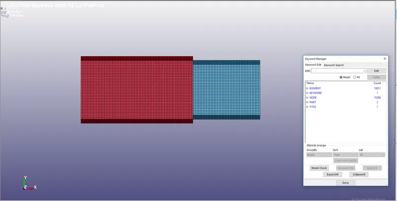
To perform the Simulation, materials, Section, initial velocity, Contact Interface, Boundary conditions, Weld elements. Output For the Following Must be Specified.
Creation of Beam:
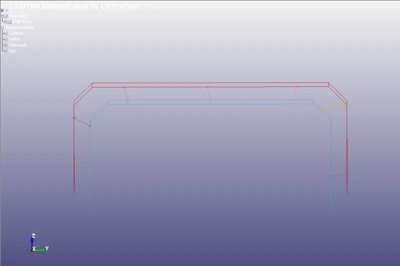
- Spot weld is modelled by using beam element is created by using the following commands
- Mesh `rarr`Element generation `rarr`Beam `rarr`New part ID `rarr`Select Beam by Two_node_sets `rarr`Select any two nodes `rarr`Create `rarr`Accept `rarr`Done
- Repeat the above steps to create 7 beams across the model to record the behaviour of the weld.
2. Assigining the material:
- We need to assign material for beam and shell elements separately
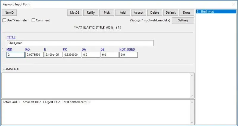
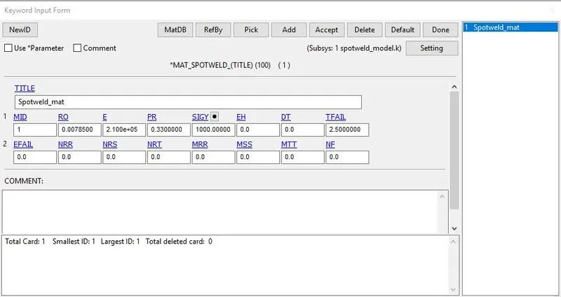
- For assigining the material the following steps are followed Keyword manager `rarr`All `rarr`Mat `rarr` Select the material card, here different material properties like mass density, youngs modulus, poisson's ratio and other recommended values are given
- For the shell elements Mat_Elastic_001 card With properties of steel assigned
- For the spotweld Mat_Spotweld_100 card with properties of steel assigned. Conditions Like TFAIL, EFAIL, Time-Dependent Failures, Force Dependent Failures With respect to Axial and Stress and resultant forces, And Moment-based Failures to the Beam elements were assigned as 2.5 ms.
- since we need to Solve This problem based On Time Based Failure All other Failures except Time are Comparatively High.
3. Section creation:
- The Section which is needed to be defined by selecting Keyword manager `rarr`All `rarr`Section `rarr`shell
- Here the solid selection with element formulation 16 ( Fully integrated ) is defined
- Similarly for creating the Section for beam which is needed to be defined by selecting Keyword manager `rarr`All `rarr`Section `rarr`Beam
- Here the solid selection with element formulation 9 ( For spot weld ) is defined
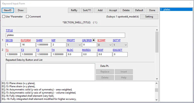
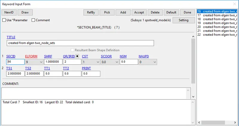
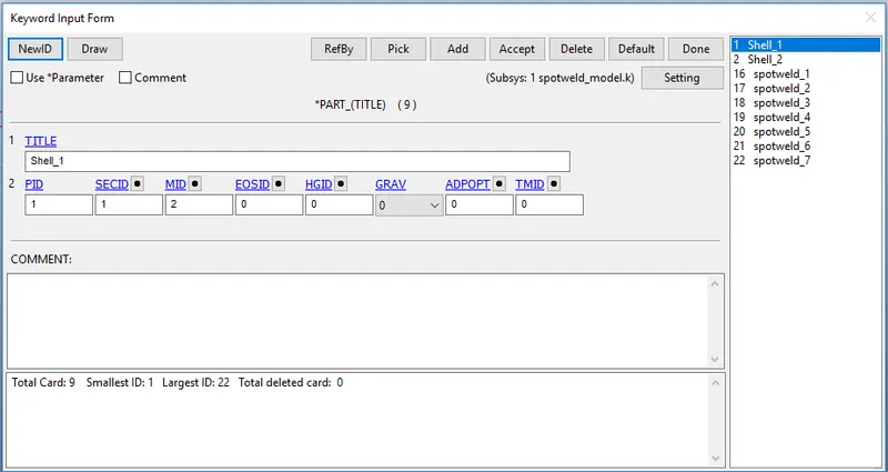
Specifying section and materials to their respective part ID's
- For creating the part Keyword manager `rarr`model `rarr` part is used , then the respective section and materials for the shell elements and beam is assigned to them respectively
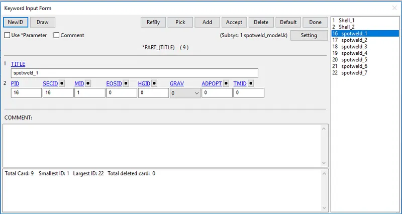
Rigid wall creation:
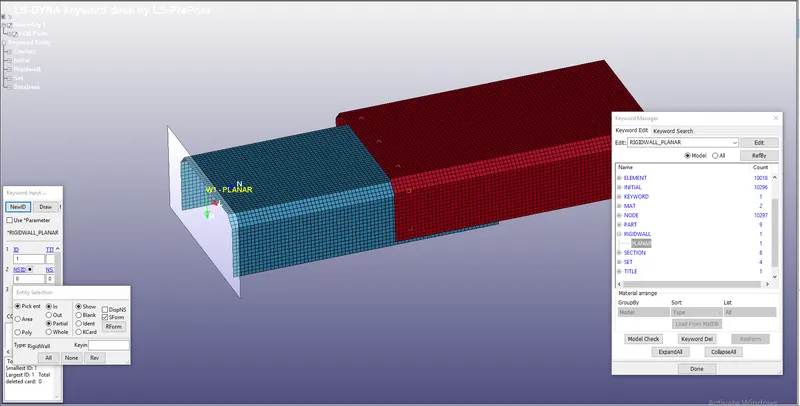
- The crash box must impact to a rigid wall, which can be created by using the following commands
- Create entity `rarr`Rigid wall `rarr`Planar `rarr`1n+Nl `rarr`Pick any node `rarr`apply
4. Contact interface:
- For the beam element, *CONTACT_TIED_SHELL_EDGE_TO_
SURFACE Contact Type is Used. - since the reactions Of the Beam is to be found It is defined as a slave And the Sheet metal parts as Master.
- For defining the Slave select beam nodes Set, The Beam nodes set is created by Entity Create `rarr`SetData `rarr` *SET_NODE `rarr` Pick the nodes `rarr` Apply.
- For Master The Part Set is created Entity Create `rarr` SetData `rarr` *SET_PART `rarr` Pick the nodes `rarr` Apply.
- Assign both the slave-set and the master-set as created by the above technique to the contact card. *CONTACT_TIED_SHELL_EDGE_TO_
SURFACE card. Select Slave-type - Node set ID and Master-type - Part set ID -
Similarly Automatic_single_
surface contact card Is created for the parts as after the Spotweld Breaks the parts shouldn't come in contact with each other.The Parts are selected as Slaves Here.
5. Initial velocity:
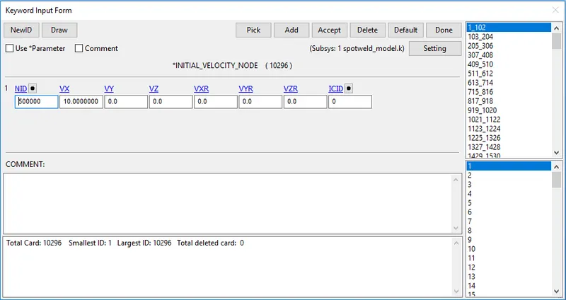
- Initial velocity is defined to the Shell elements by Keyword manager `rarr`New `rarr` Initial `rarr` Velocity
- The velocity is found out to be 10 mm/ms
6.Control cards :
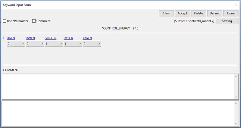
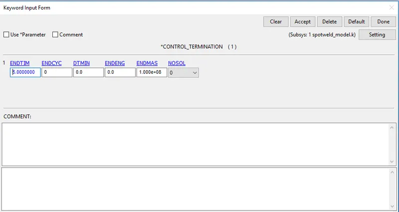
- Control cards such as control energy which is used to specify the control of hourglass energy and control termination which controls the termination of the end time of simulation are specified here
- Keyword manager `rarr`All`rarr` control `rarr` Energy/Termination command is used to define control energy and control termination, here the endtime is chosen as 5ms with DT as 0.5
For solid Elements:
creation of solid Elements:
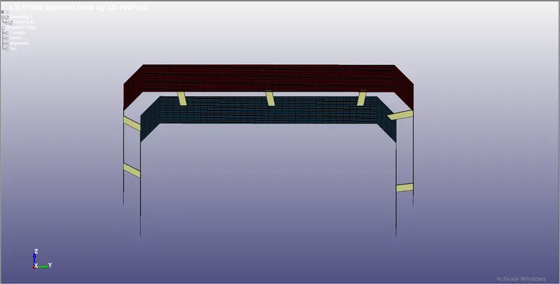
- The spot weld modeled using beam element is created by selecting the Element tools `rarr` Element edit `rarr` Create `rarr` Element type:Hexa `rarr` select 8 nodes `rarr` Accept `rarr` Done.
- SInce Element Type- Hexa is selected, 8 nodes are selected From the element where The solid elements to be Formed In between. Create 5 elements at different places.
Creating a section:
- The Section which is needed to be defined by selecting Keyword manager `rarr`All `rarr`Section `rarr`solid
- Here the solid selection with element formulation 1 ( default) is defined
Material assigning:
- For the spotweld Mat_Spotweld_100 card with properties of steel assigned. Conditions Like TFAIL, EFAIL, Time-Dependent Failures, Force Dependent Failures With respect to Axial and Stress and resultant forces, And Moment-based Failures to the Beam elements were assigned as 2.5 ms.
- since we need to Solve This problem based On Time Based Failure All other Failures except Time are Comparatively High.
Specifying section and materials to their respective part ID's
- For creating the part Keyword manager `rarr`model `rarr` part is used , then the respective section and materials for the shell elements and beam is assigned to them respectively
CONTACT INTERFACE:
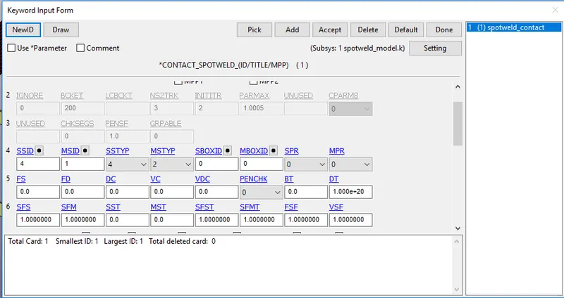
- The Contact Created Remains the same for the Sheet metal plates.For the Solid element, CONTACT_SPOTWELD is used.
- Since we need to Know the Reactions Of the Solid elements It is defined as a slave And the Sheet metal parts as Master.
7. Output request:
- Generally output resquest are specified to view the results of the simulation which is done by the following commands
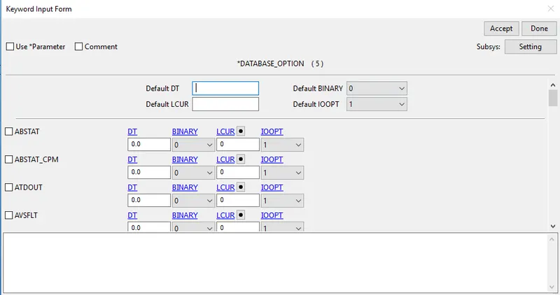
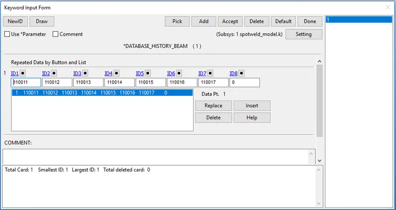
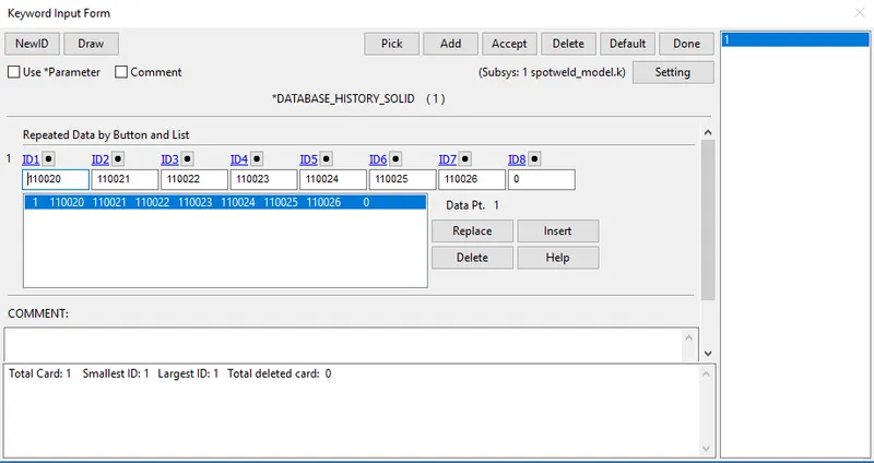
- Keyword manager `rarr`All`rarr` Database`rarr` ASCII_option from which GLSTAT, ELOUT,MATSUM, SWFORC & RCFORC option is selected with DT= 0.5 ms
- GLSTAT is defined with DT=0.5 ms which gives the output of energies such as Internal energies, kinetic energy & other types of energies
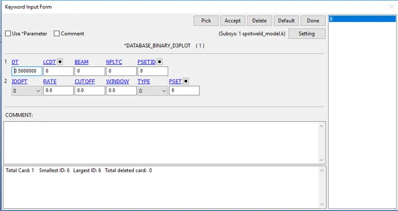
- Keyword Manager `rarr`Database `rarr` Binary D3plot `rarr` DT 0.5, this command prints the output at the end of each 0.5 ms
- The database ELOUT is defined so that the spotweld are defined in History node/solid Respectively
8. Run the simulation
- The keyword is saved in a separate folder and it is opened in Ls-Dyna manager and the simulation is made to run for solid and beam elements separately
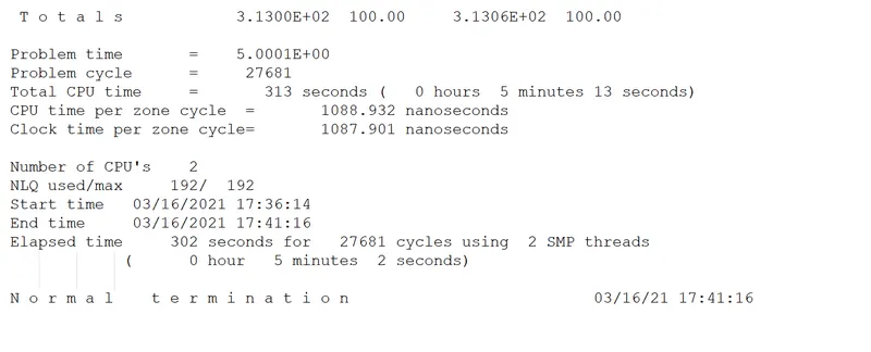
- From The Output, file Check the Time in which Solid and Beam Elements failing With the Time Specified in the TFAIL.
Output for Beam spotwels:
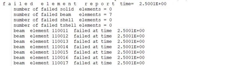
Since Tfail 2.5 ms it can be noted that the beam elements are failing at time 2.5ms
Von-mises observation:
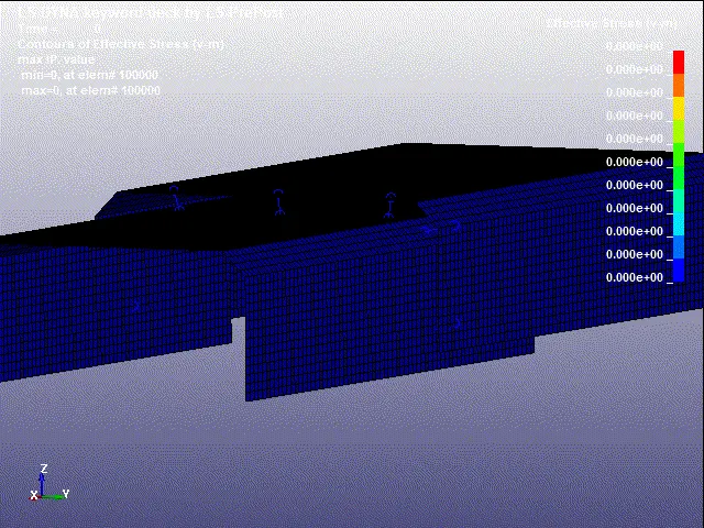
Note: The Rigid wall is made to hidden to view the deletion of elements
From the Simulation:
The Maximum Stress is 938.62 mpa at element 10836
The Minimum Stress is 0mpa at element 110011
Graph:
1. Energy graph:
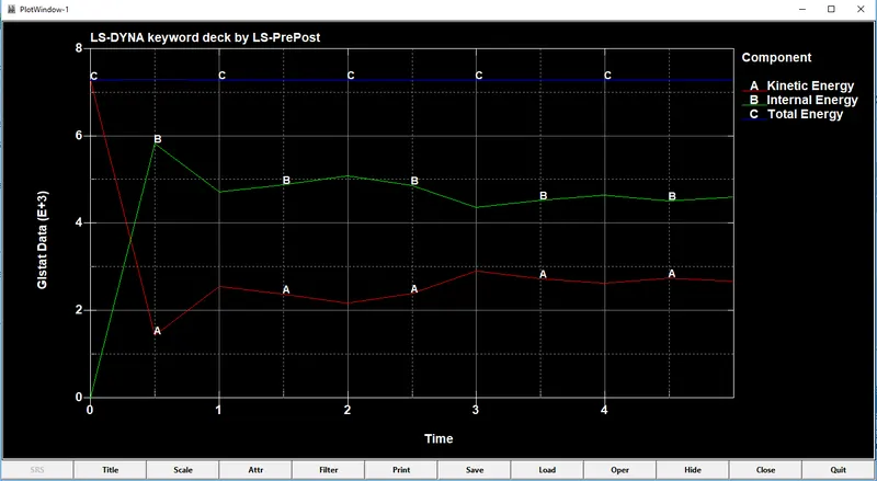
- From the above graph it can be seen that there is sudden drop in kinetic energy after the impact
- whereas the internal energy is increasing at the time of impact
- Also the total energy remains constant throughout by satisfying the Law of conservation of Energy
2. Spotweld Forces:
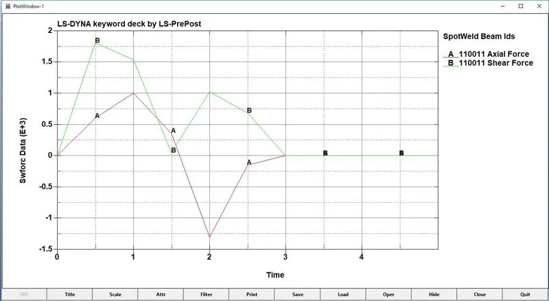
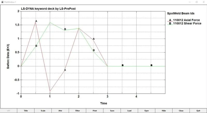
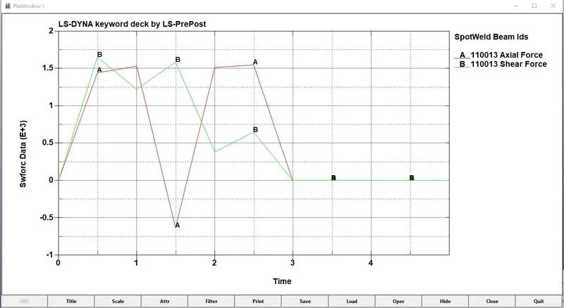
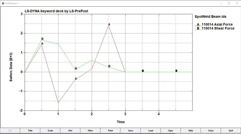
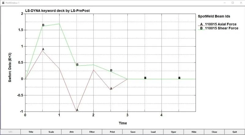
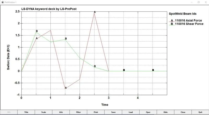
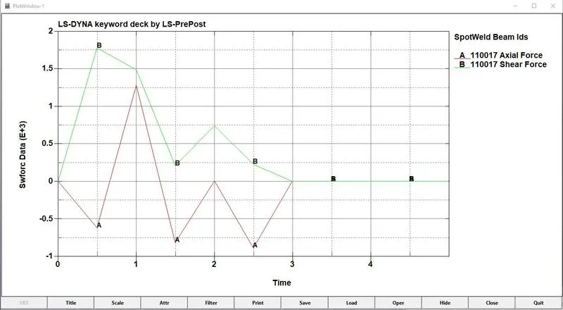
From the above graph, we can see that the Axial and Shear forces of Beam elements Getting deleted at 2.5 ms which is assigned as the TFAIL value
Output for Solid spotwels:
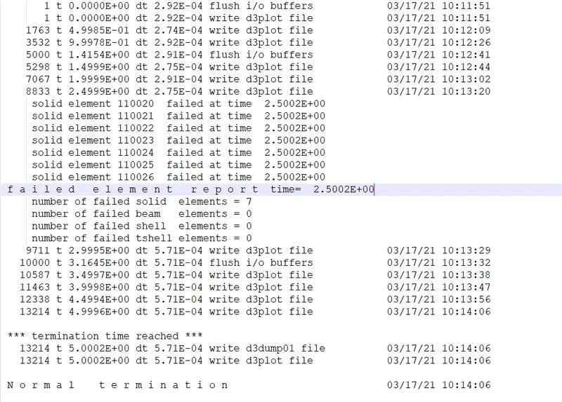
Since Tfail 2.5 ms it can be noted that the beam elements are failing at time 2.5ms
Von-mises observation:
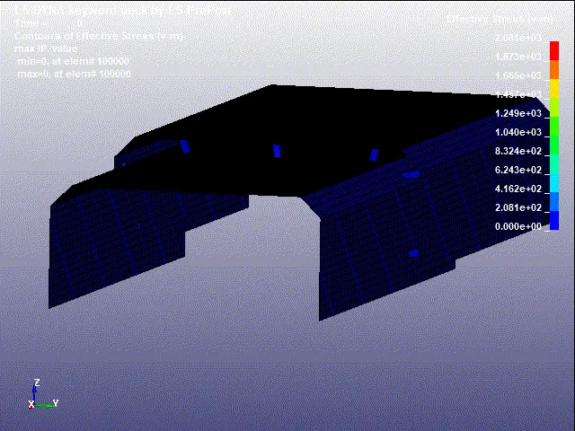
Note: The Rigid wall is made to hidden to view the deletion of elements
From the Simulation:
The Maximum Stress is 2080.95 mpa at element 104410
The Minimum Stress is 0mpa at element 100022
Graph:
1. Energy graph:
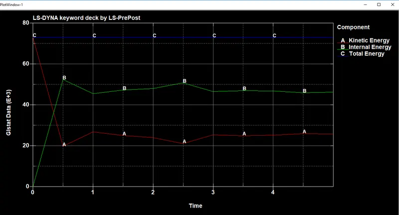
- From the above graph it can be seen that there is sudden drop in kinetic energy after the impact
- whereas the internal energy is increasing at the time of impact
- Also the total energy remains constant throughout by satisfying the Law of conservation of Energy
2. Spotweld Forces:
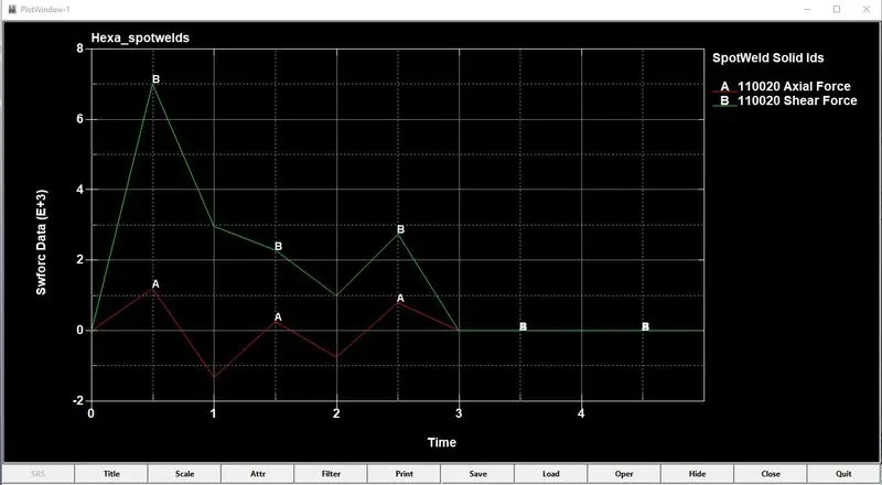
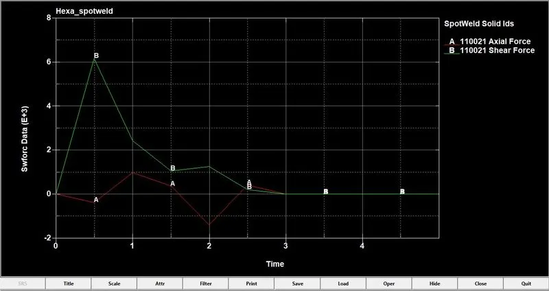
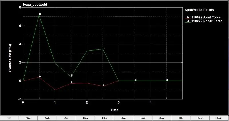
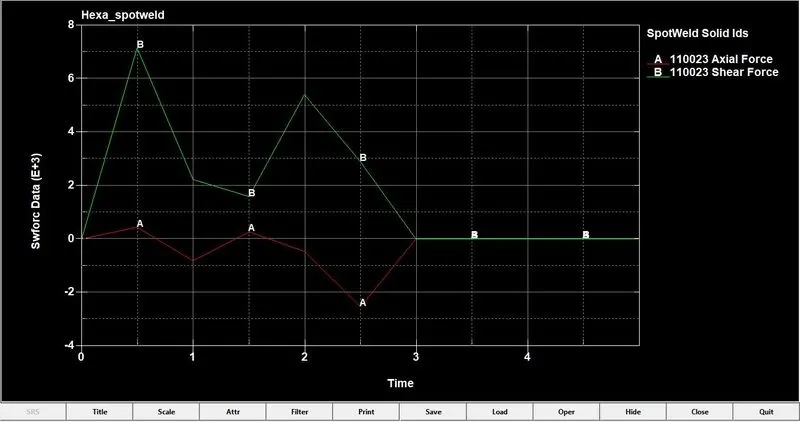
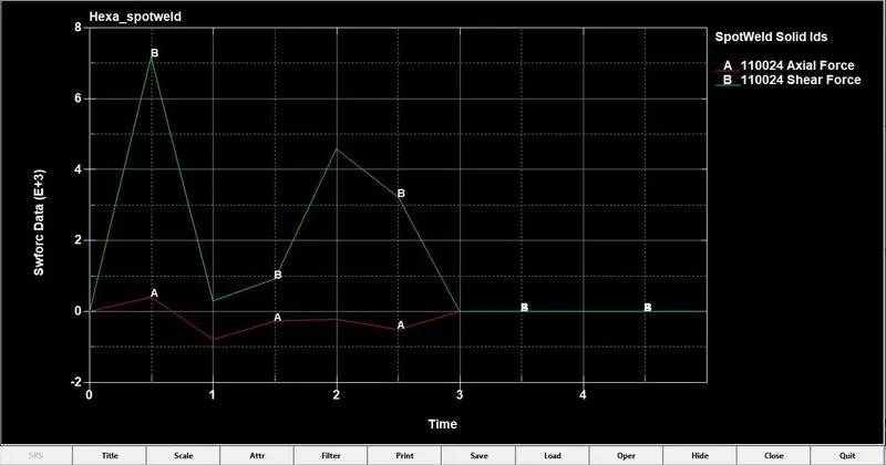
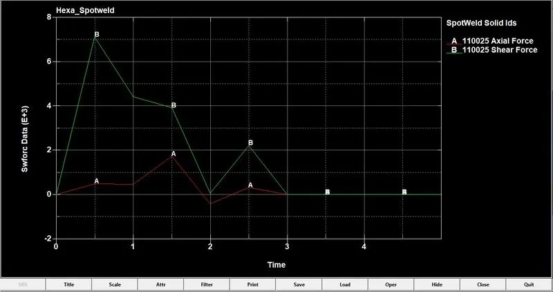
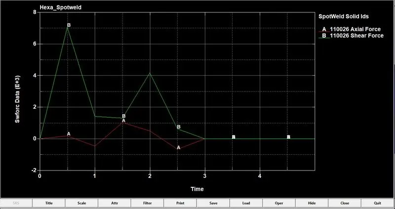
From the above graph, we can see that the Axial and Shear forces of Beam elements Getting deleted at 2.5 ms which is assigned as the TFAIL value
Observations:
- The Beam element Created Takes load axially More than Shear force
- The force acting on the spot weld is in the transverse direction (perpendicular to the axis) since the solid element gives the force-resisting ability in the transverse direction, higher shear force values are notices for a solid element than beam element.
Conclusion:
The spot-weld is modelled for the given assembly parts using beam and solid elements separately and their results are compared and plotted.