Week - 5 - Modelling Spotwelds
AIM:-To perform crash stimulation of box which are to be connected with respect weld by beams and solids.
PROCEDURE:-
- Import the model into ls pre_post.
- To import the model we need to open ls prepost and click on File and select the option import.
- Then select the keyword file and click on apply.
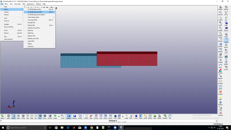
- Then after we need to assign the material and section property to the parts.
- Before that, we need to create the beam and solid elements to weld.
- To create the beams or solids we need to go to the mesh module and select element edit.
- To create select two nodes for beam and eight nodes for solid, make sure that we should select in a linear pattern.
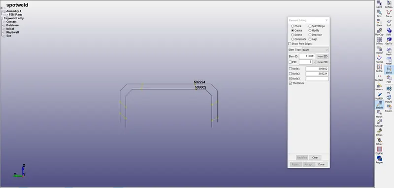
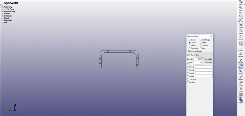
- After creating connections we need to specify material and section to the part created.
- There are two components which are weld with beam and weld with solids.
WELD WITH BEAM ELEMENTS:-
- To create material property we need to go to Keyword in the model module.
- Select the MAT and select piecewise plastic material and give the value to the variables for the material.
- For these, we are considering the property of steel for all
- For creating material for the beam we need to select spotweld as the material and give the values for the variables.
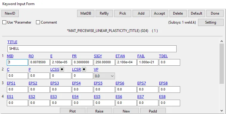
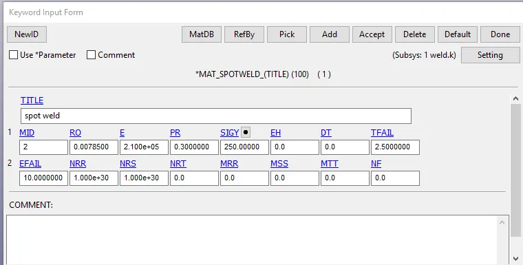
- After the creation of materials, we need to create the section for the parts.
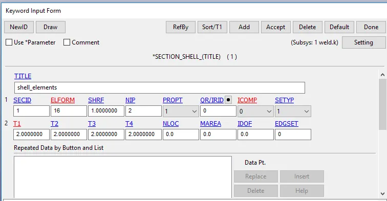
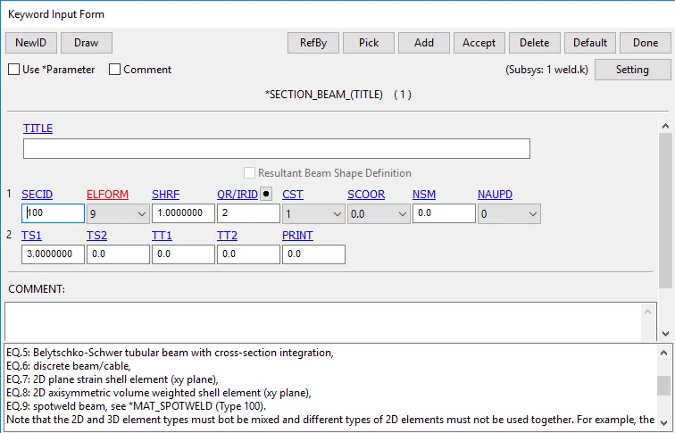
- To create the section we need to select a section from the keyword file.
- For the shell, element formulation will be 16, and for beam, it will be 9.
WELD WITH SOLID ELEMENTS:-
- To create material property we need to go to Keyword in the model module.
- Select the MAT and select piecewise plastic material and give the value to the variables for the material.
- For these, we are considering the property of steel for all
- For creating material for the beam we need to select spotweld as the material and give the values for the variables.
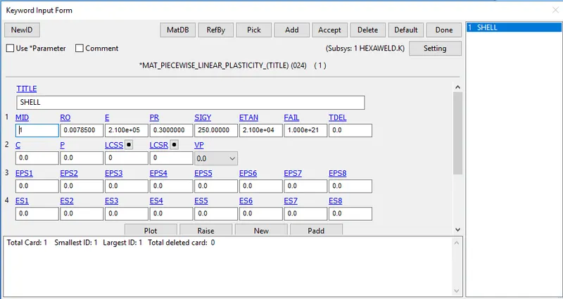
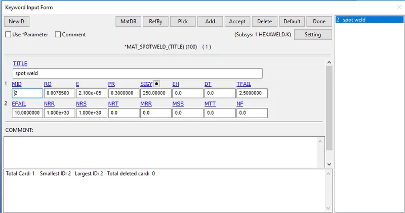
- After the creation of materials, we need to create the section for the parts.
- To create the section we need to select a section from the keyword file.
- For the shell, element formulation will be 2 and for solid, it will be 2.
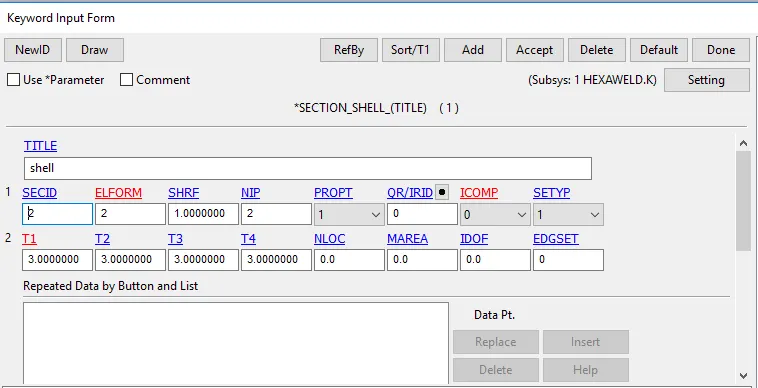
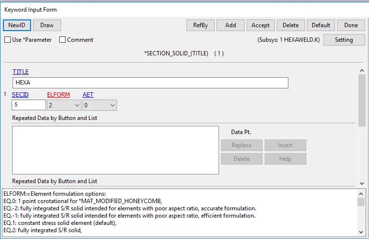
- Assign everything to part by selecting the ids of shell and material.
- After this, we need to create a rigid wall.
- To create the rigid wall we need to go to entity creation and select rigid wall
- select planar and select on create then click on the node and by translate move the wall.
- After that, we need to give the velocity of 13.6 mm/ms
- To give velocity we need to select the initial and select velocity and select the nodes and apply.
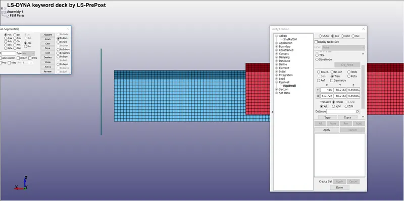
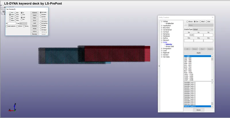
- Make sure that normal should be opposite to the direction of motion.
- Then we need to give the contacts between two shell and beam elements.
- The contact between the shell is automatic single surface contact, where we should create a set of all shell elements.
- And for the beam and shell, we need to give a tied contact where the beam is the slave and the shell is the master.
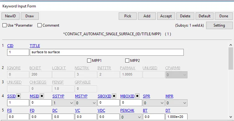
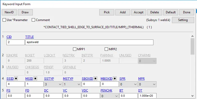
- The contact between the shell is automatic single surface contact, where we should create a set of all shell elements.
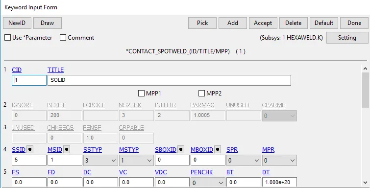
- And for the solid and shell, we need to give a spot weld contact where the solid is the slave and the shell is the master.
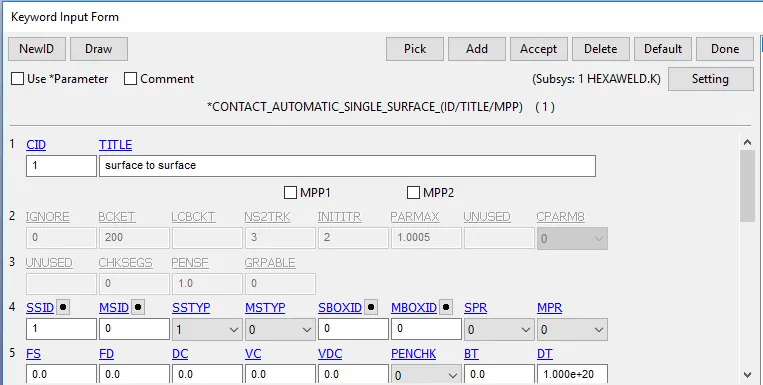
- Now we need to output the request to the problem.
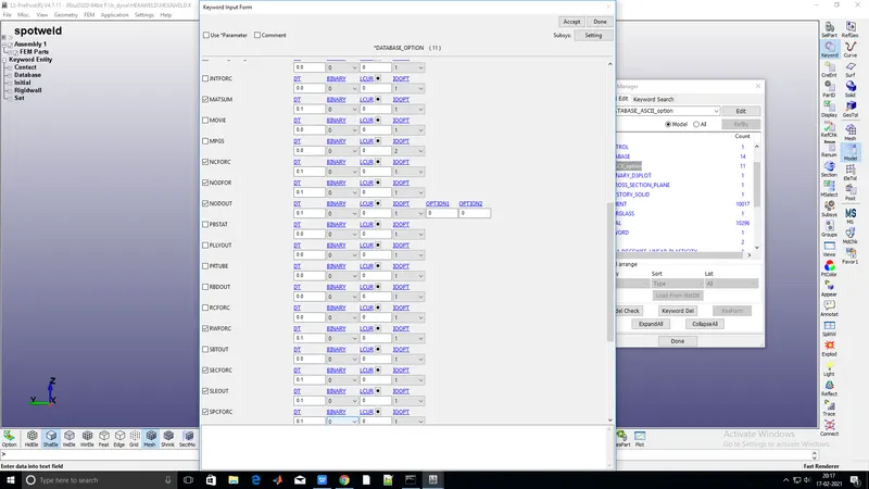
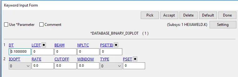
To give an output request we need to go to the database and give ASCII and BINARY POLT.
- ELOUT:-database for element results for SSD (stress and strain
components). - D3PLOT:-Database for the entire model.
- GLSTAT:- file is the sum of internal energy of discrete elements.
- MATSUM:- Energy values part by part.
- SPCFRC:-Single point force constrained
- SWFORC:- Spot weld forces
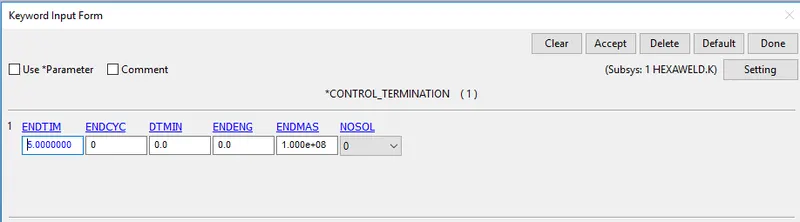
- After this, we need to specify the end time to run the simulation.
OUTPUT RESULT:-
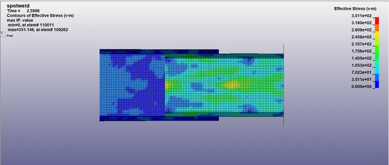
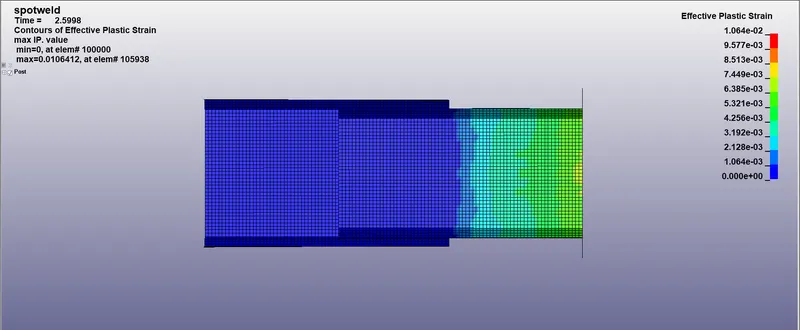
Result for the component with weld as the solid.
Result for the component with weld as the beam.
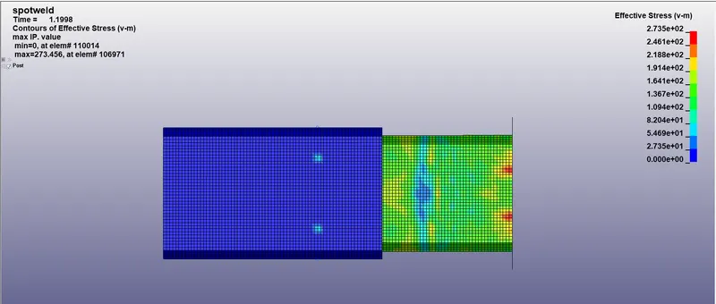
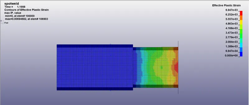
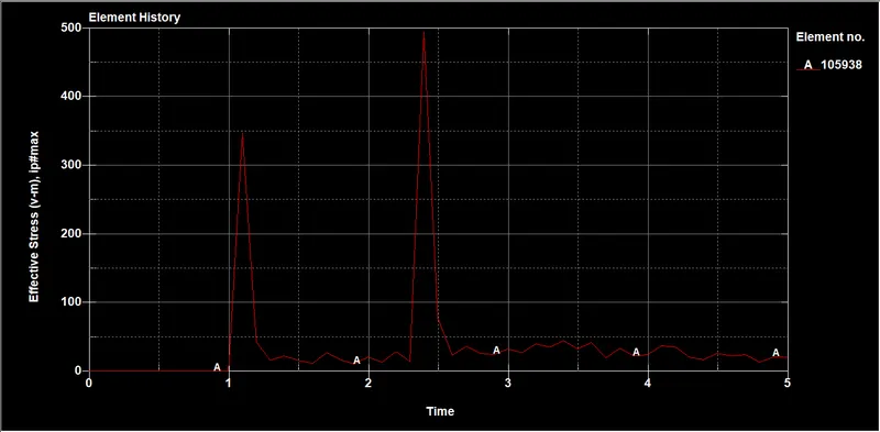
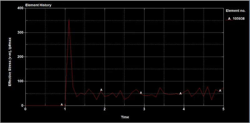
- As we can see that the max stress attained for the Hexa weld is 500gm/mm*ms^2 and for the beam, it is 328 gm/mm*ms^2.
- From these, we can understand that the max stress is attained by the Hexa element and it is been withstood up to the failure time.
stress obtained for weld by Hexa element stress obtained for weld by beam elements
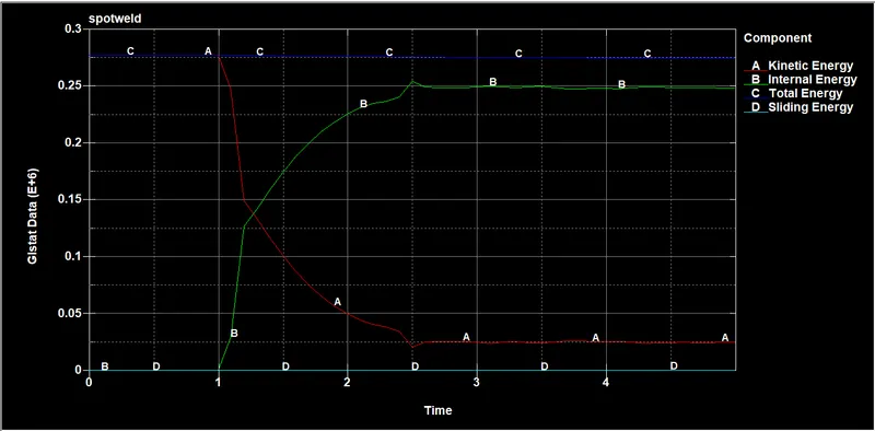
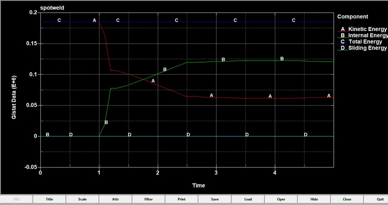
- The crash started at 1ms and then the and then we can see that there drop in K.E and there is an increase in internal energy.
- The max energy attained for the Hexa element is 274420 g*mm^2/ms^2 and for the beam, the element is 184626 g*mm^2/ms^2
- But there a constant and gradual drop in the Hexa weld which is smooth but if we see the beam there is sudden changes are been occurred in the curve that is not acceptable
- And we can see that Hexa element has attained high energy and it can withstand high velocity or load.
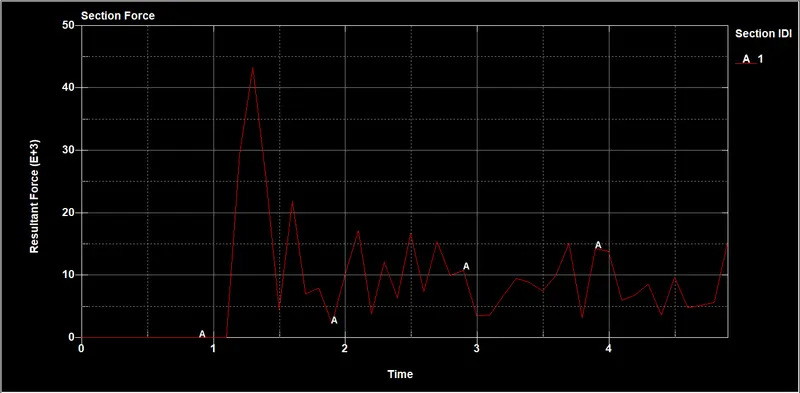
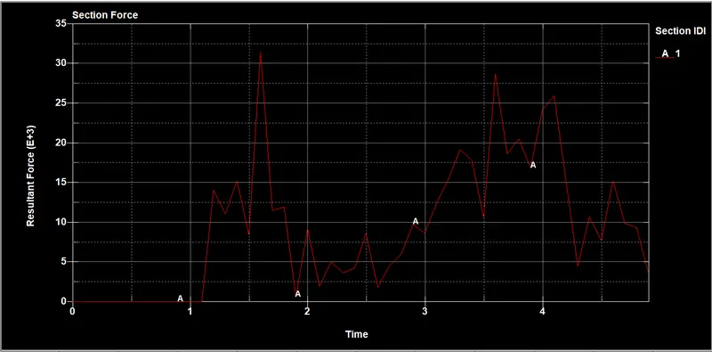
- The force attained by the Hexa weld is 43291 gm*mm/ms^2and for the beam is 31431 gm*mm/ms^2
- As the Hexa element is there a high amount of force is been attained because it has made the component highly rigid
- But the beam element are been not rigid so that we can see the fluctuating of the force
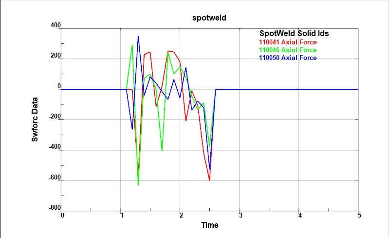
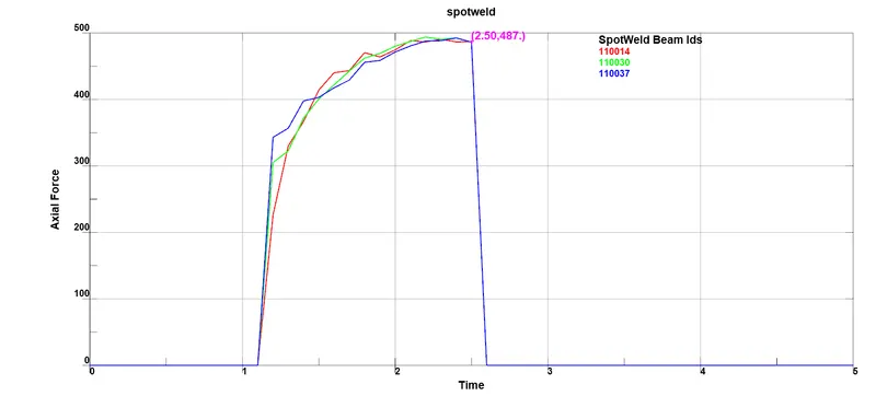
- But in the Hexa weld, a high amount of axial forces are observed in the weld due to its rigid behavior but the beam has linear raise in the forces and after the time fails it is been deleted.
- There is the linear distribution of the force to the connected component but the Hexa unable to have that property it has been behaving like rigid.
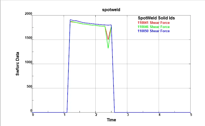
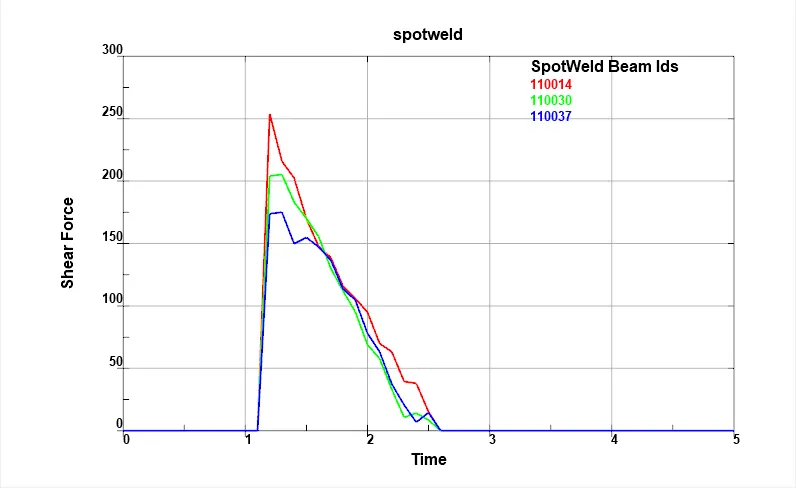
- As hexa has the high shear resistance so that the Hexa element is able to withstand but the force is been attained by the beam is very less
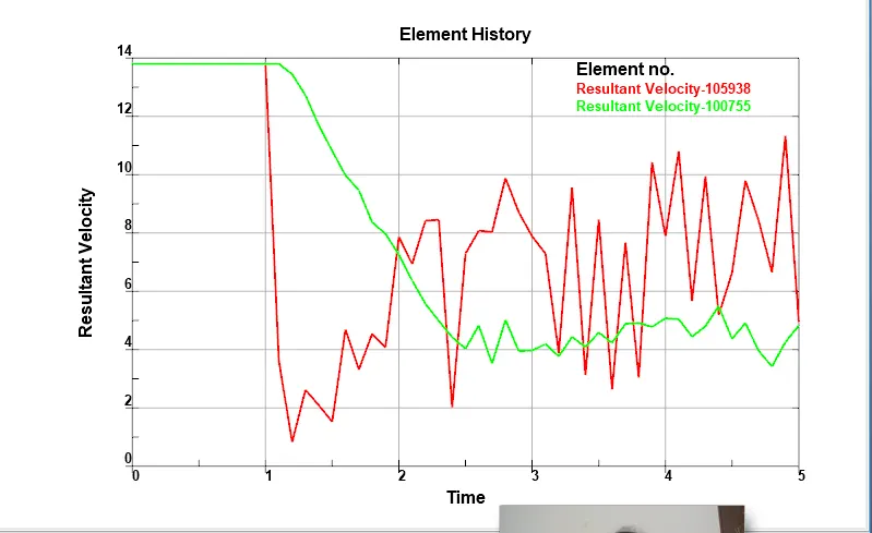
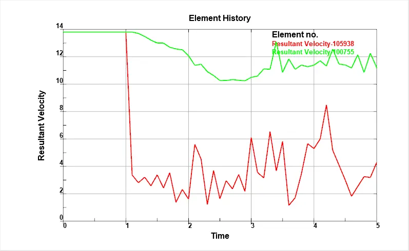
- From this, we can state that the for Hexa element the velocity is been gradually distributing to the other component.
- But the beam element has not attained the same velocity as the component attached.
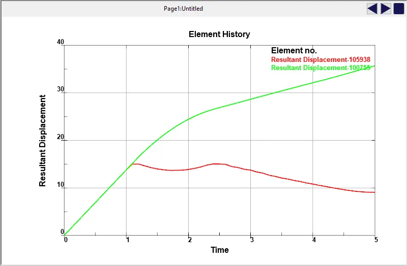
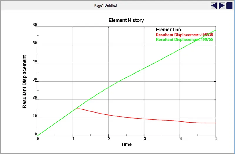
- The displacement of component 1 and 2 have noticeable displacement with respective component 1
- But the beam element has a high drop in displacement with respect to the component.
CONCLUSION:-
- Understood how to perform weld connection.
- Understood different ways to perform weld.
- understood and performed weld creation by different contacts.
- Understood the difference between the beam and solid element weld creation.