Week - 5 - Modelling Spotwelds
Objective: The objective of this project is to model spotwelds for an assembly of parts and run a crash test simulation using LS-DYNA. The spotwelds are modeled using both beam and solid elements, and their performance is compared in terms of axial and shear forces, stress, strain, and energy plots.
Theory: Spot welding is a resistance welding process used to join two or more metal sheets by applying pressure and heat from an electric current to the weld area. The result is a series of small, localized welds known as spotwelds. This technique is widely used in the automotive industry for its efficiency and strength, playing a critical role in ensuring the structural integrity and safety of vehicle assemblies.
In finite element analysis (FEA), spotwelds can be modeled using various element types to represent their mechanical behavior accurately. The most common approaches are:
- Beam Elements: Simplified representation using line elements that capture the essential mechanical properties of spotwelds, including stiffness and load-bearing capacity.
- Solid Elements: Detailed representation using 3D elements that provide a more accurate depiction of the spotweld’s physical characteristics and failure modes.
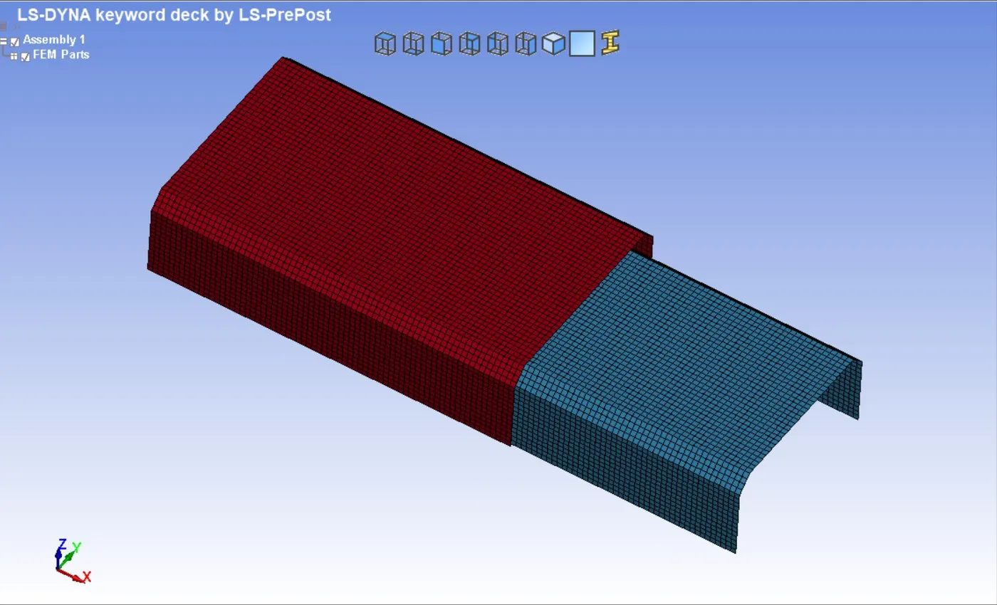
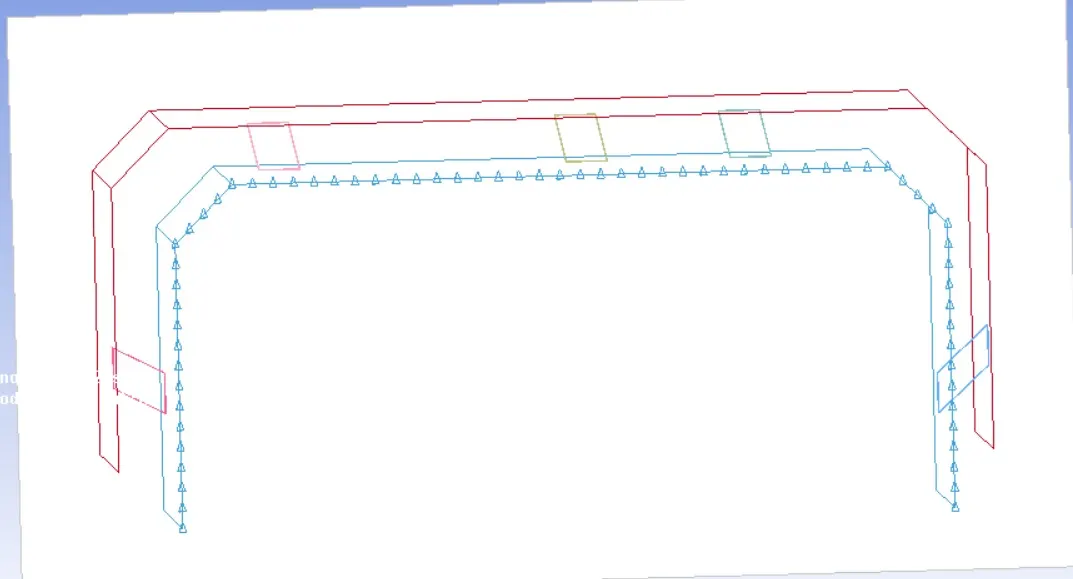
Model Image:
Procedure:
CASE 1: Beam Element
1) Open the Keyword file in LS Pre-Post Deck.
To open a keyword file in LS-PrePost, go to File > Open, navigate to your file, select it, and click Open.
We can see that there are two plates which are needed to weld.
2) Spot Weld Beam Generation
go mesh > ElemGen > Beam > Beam by = Two_Node-Sets > Pic Node set 1 > Pick Node Set 2 > Create
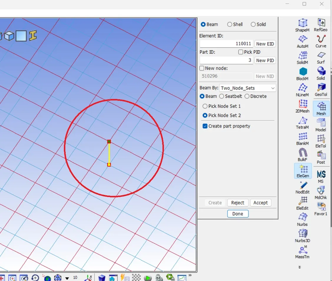
This beam element will be act as spotweld.
Similarly draw six beam elements along a line
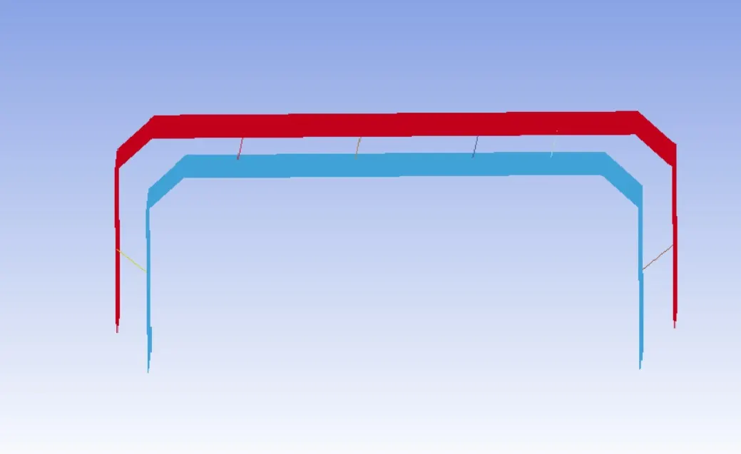
By default material and section card will be created. we will delete these cards and create appropriate card.
3) Creating Material Card and Section Card
Material Card for Beam
Go to Model and Part > Keyword > All > Material >> MAT_SPOTWELD >> Give required value
Here TFAIL (Time of failure should half of the termination time.)
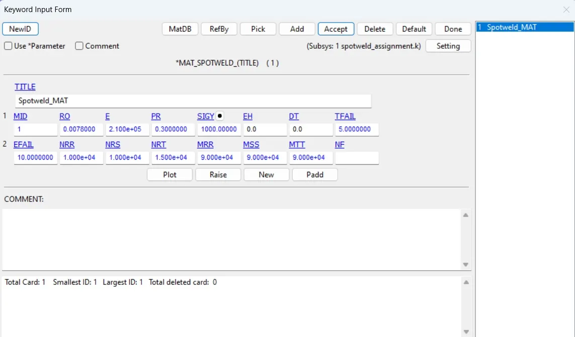
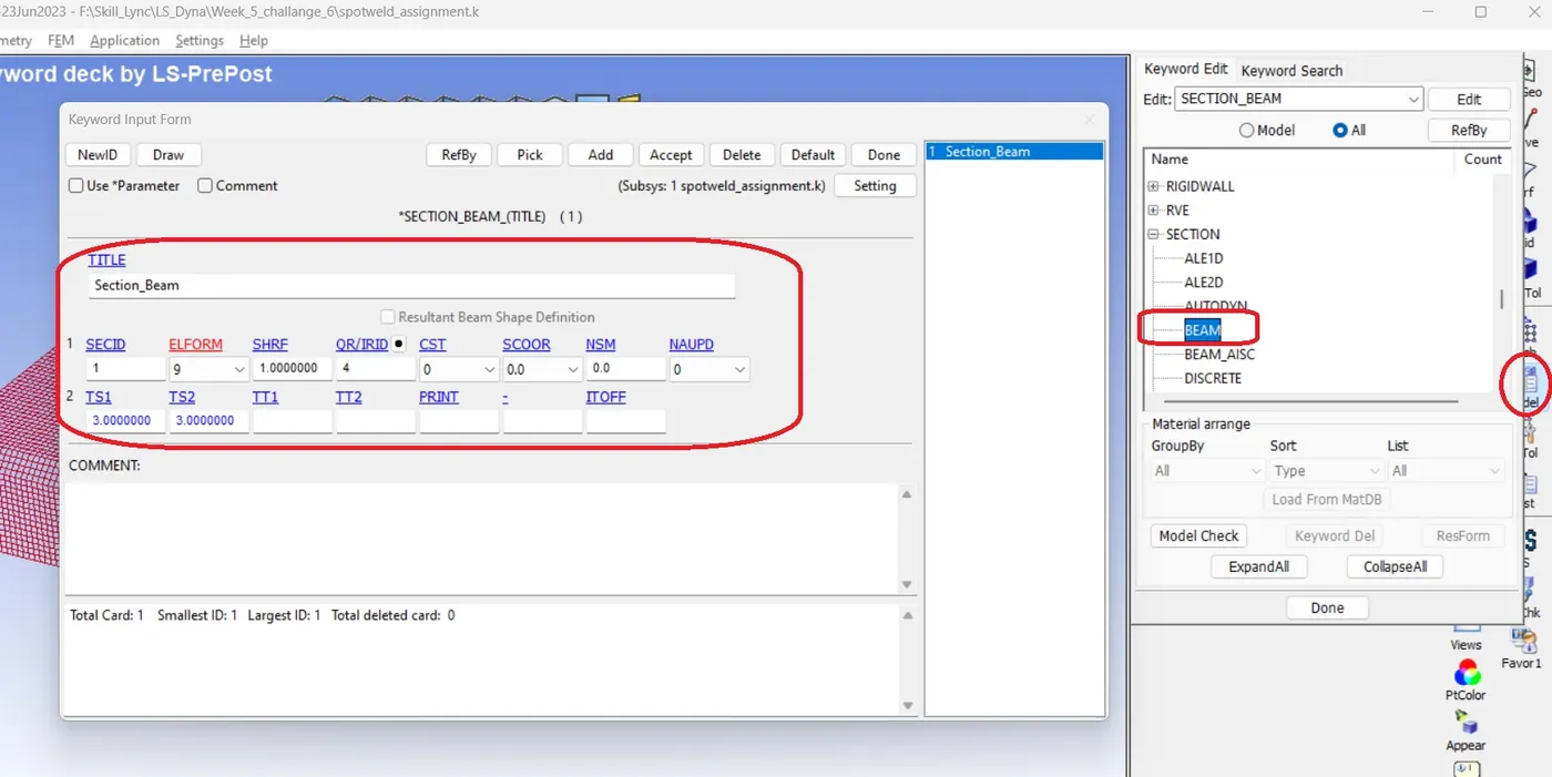
Section Card for Beam
Go to Model and Part > Keyword > All > Section >> Section_Beam >> Give required value
Put CST value = 1 for the tubular cross section
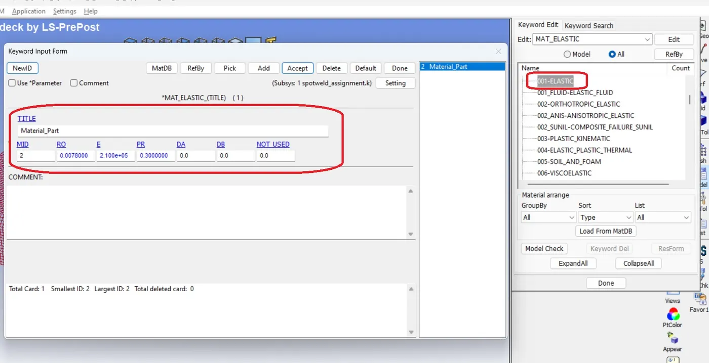
Material card for Part
Go to Model and Part > Keyword > All > Material >> MAT_Elastic >> Give required value
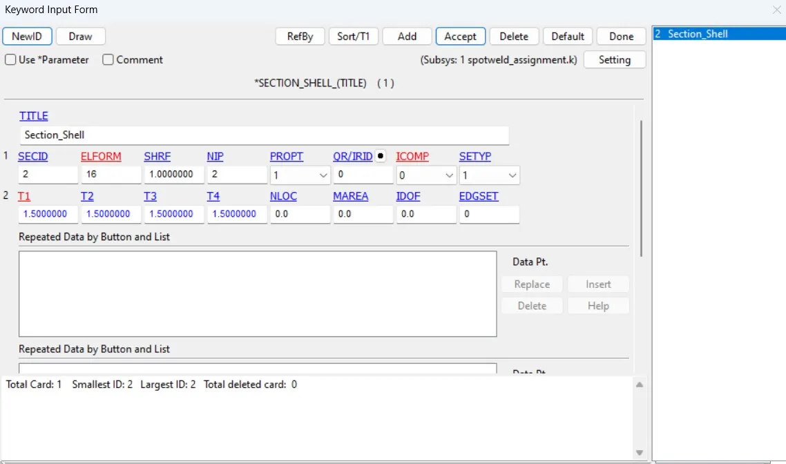
Section Card for Part
Go to Model and Part > Keyword > All > Section >Shell > Give required value
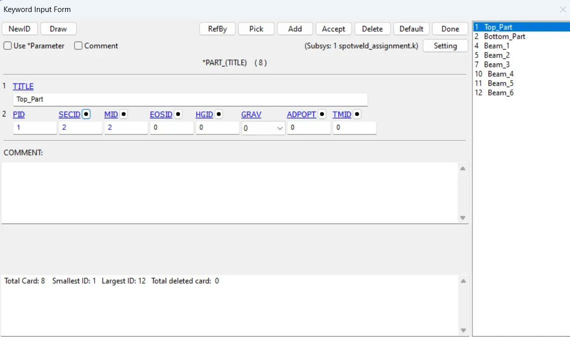
4) Applying Section card and Material Card to beams and Top and Bottom parts
Go to Model and Part > Keyword > Part > Part > Select section Id and Material Id for the part.
5) Create Contact Card
we will use following contact card for spotweld
*CONTACT_TIED_SHELL_EDGE_TO_SURFACE
First Create Node set for beam Elements. For this go to Create Entity > Ste Data > Set Node > Create > Select beam nodes > Done
Similarly create part set for part elements. For this go to Create Entity > Ste Data > Set Part > Create > Select Parts > Done
Now, go to Model and Part > Keyword > all > Contact > TIED_SHELL_EDGE_TO_SURFACE>> fill required value
Select Node Set as SurfA (Slave Set) and Part Set as SurfB (Master Set)
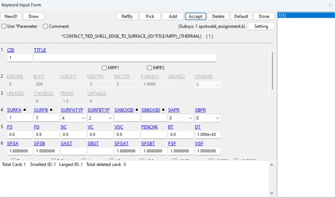
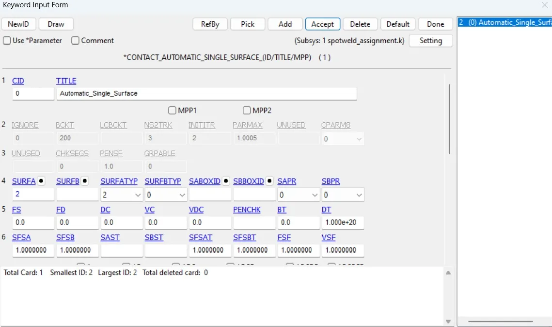
Now Create CONATCT_AUTOMATIC_SINGLE_SURFACE card so that, the two parts does not penetrate to each other.
For this go to Model and Part > Keyword > all > Contact > Automatic_Single_Surface >
Here SurfaceAtype is 2 and Surface A should be Part Set that we have created earlier
6) Apply Boundary Condition
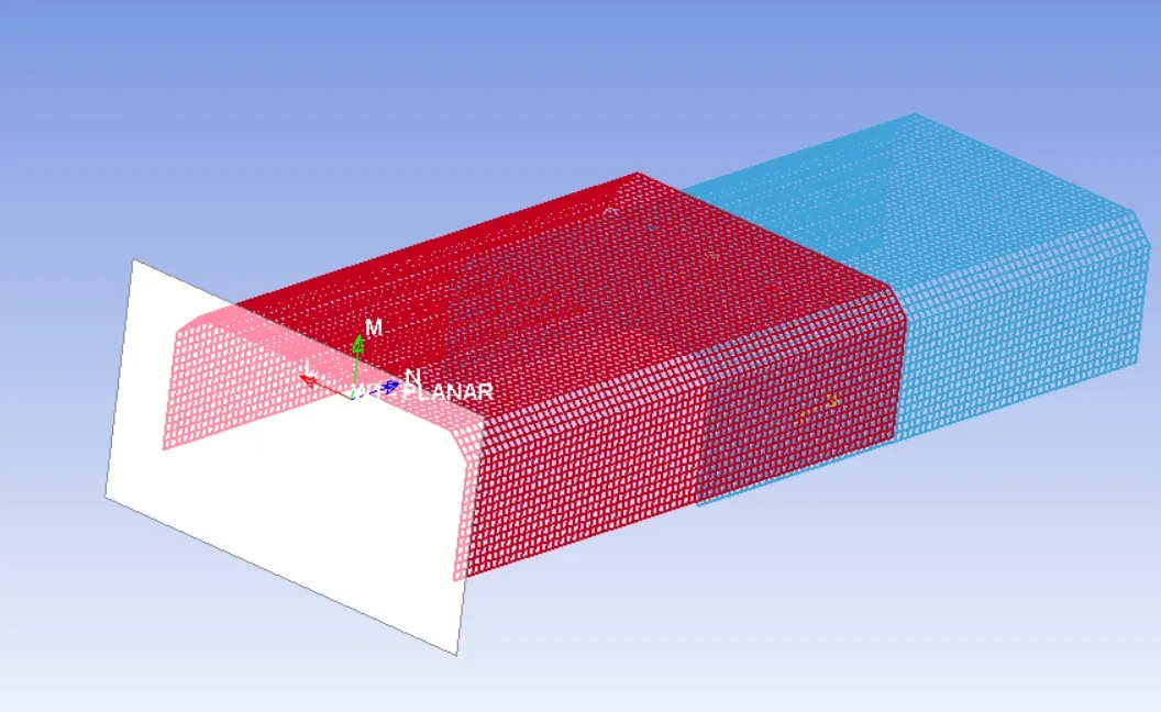
First, Create Rigid Wall
for this go to Model > Create Entity > Boundary > Rigid Wall > Create > Planar > 1n+NL > select a node at edge > translate the plane by 10 mm > Apply > Done
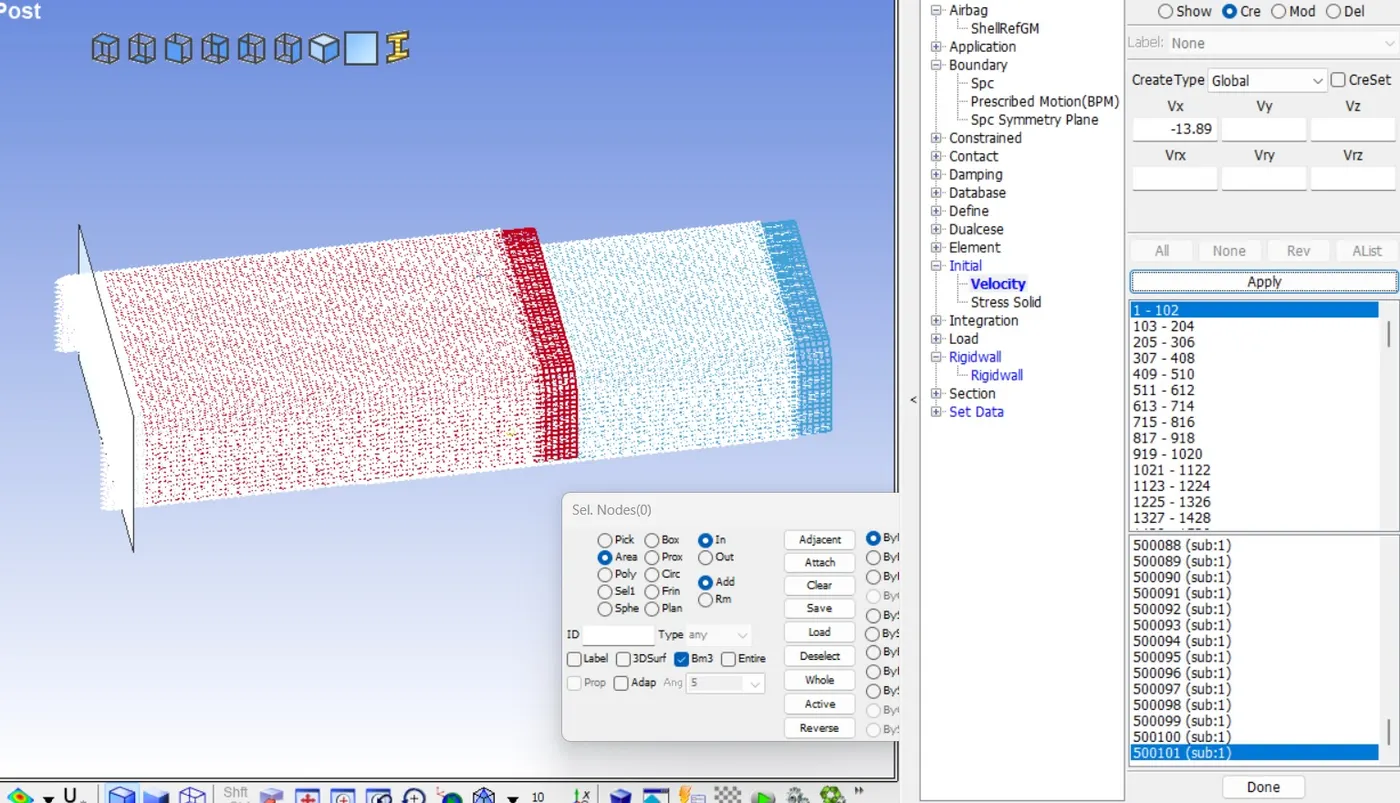
Give initial Velocity to the Model
for this go to Model > Create Entity > Boundary > Initial > velocity > Select nodes > give velocity in negative x direction i.e. -13.89 m/s
7) Control Termination
For this go to Model and Part > Keyword > all > Control > Termination > Endtime = 10
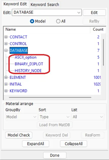
8) Database Output
For this go to Model and Part > Keyword > all > Database > Change DT = 0.1 for following
ASCII - GLSTST , SWFORC, NODOUT, MATSUM, ELOUT, SECFORCE
BINARY DL3PLOT
For History_Node - Give ID of spot weld node
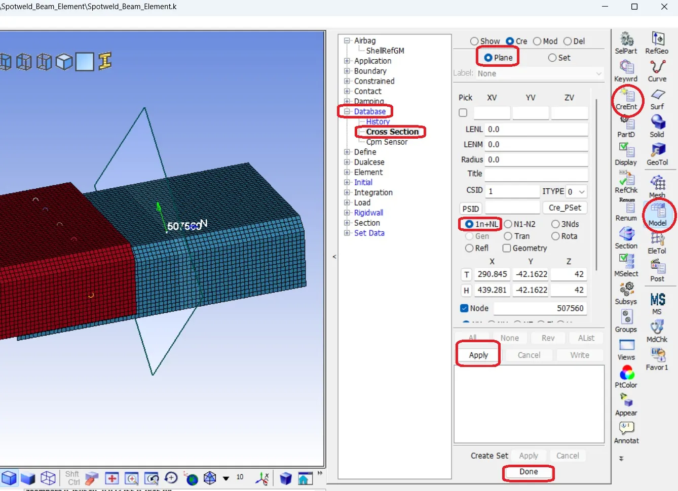
9) Create a cross section plane to analyse sectional force
For this go to Model > Create Entity > database > Cross Section > Create > Plane
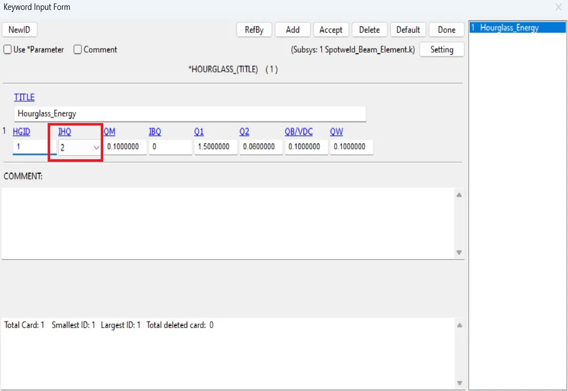
10) Create Hourglass Card and add it to part
11) Save the model and Run in LS Run and then Open the binary file in LS Prepost for Postprecessing.
CASE 2: Hexa Solid Spot Weld Element
9 In the above mode do the few minor change
1) Spotweld Solid Hexa Element Generation
EleTol > EleEdit > Create > Hexa > select 8 nodes, 4 from top shell and 4 from bottom shell just beneath the top nodes > Accept > Done
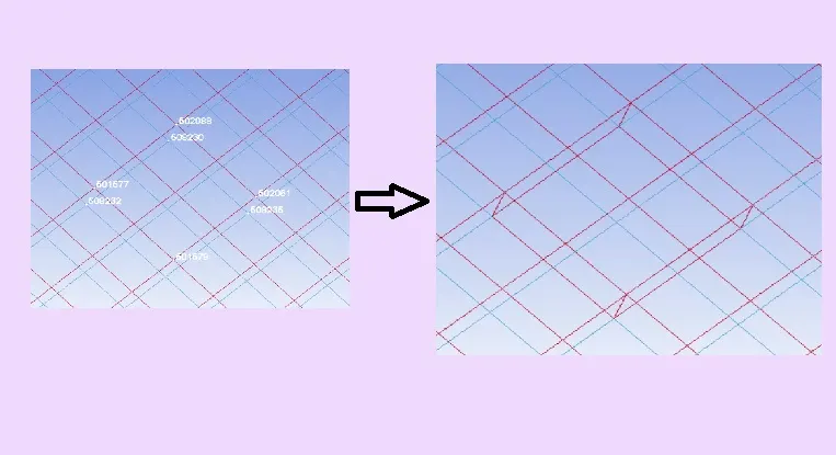
Create 5 solid hexa elements in a line.
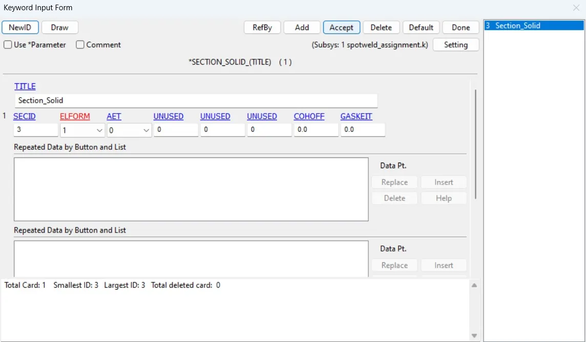
2) Material Card will be same but section card has to be change as solid and elform should be 1
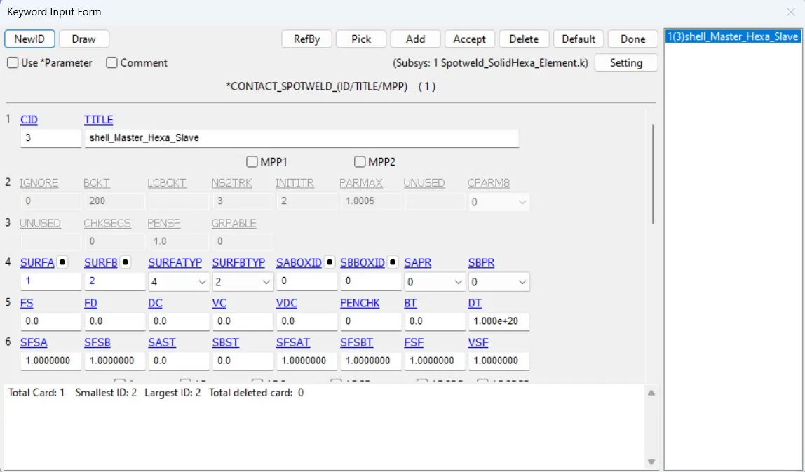
3) Contact Card
Define the contact type for spotweld in solid element as CONTACT_SPOTWELD create as a part and define spotweld as slave and shell as master.
RESULT
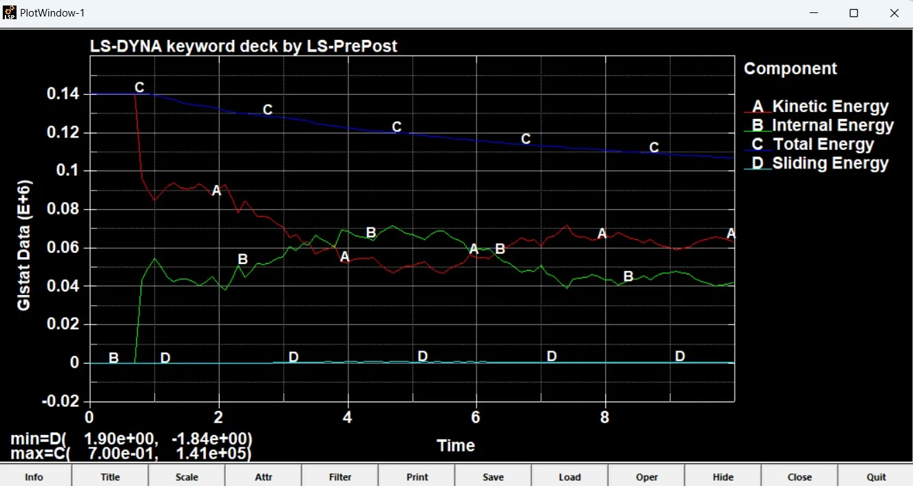
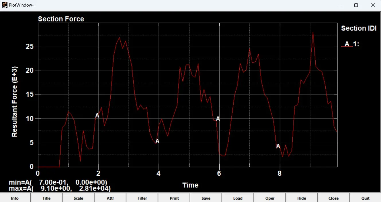
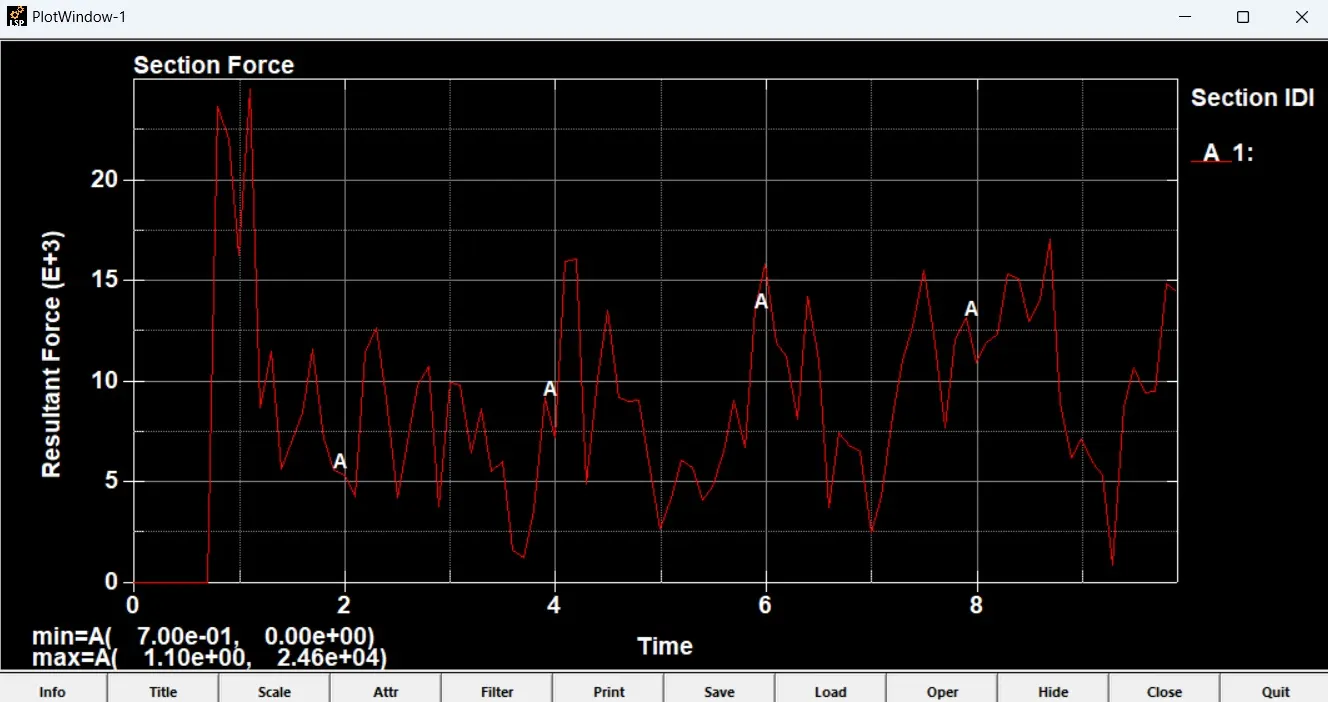
A Comparison is made between the beam and solid elements as shown below:
Energy Plot
Energy Graph for spotweld Beam Element
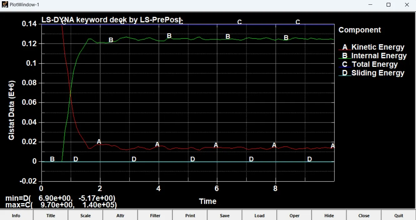
Energy Graph for Solid Hexa Element Spotweld
Section Force Plot
Section Force for Beam Element Spotweld
Section Force for Solid Hexa Element Spotweld
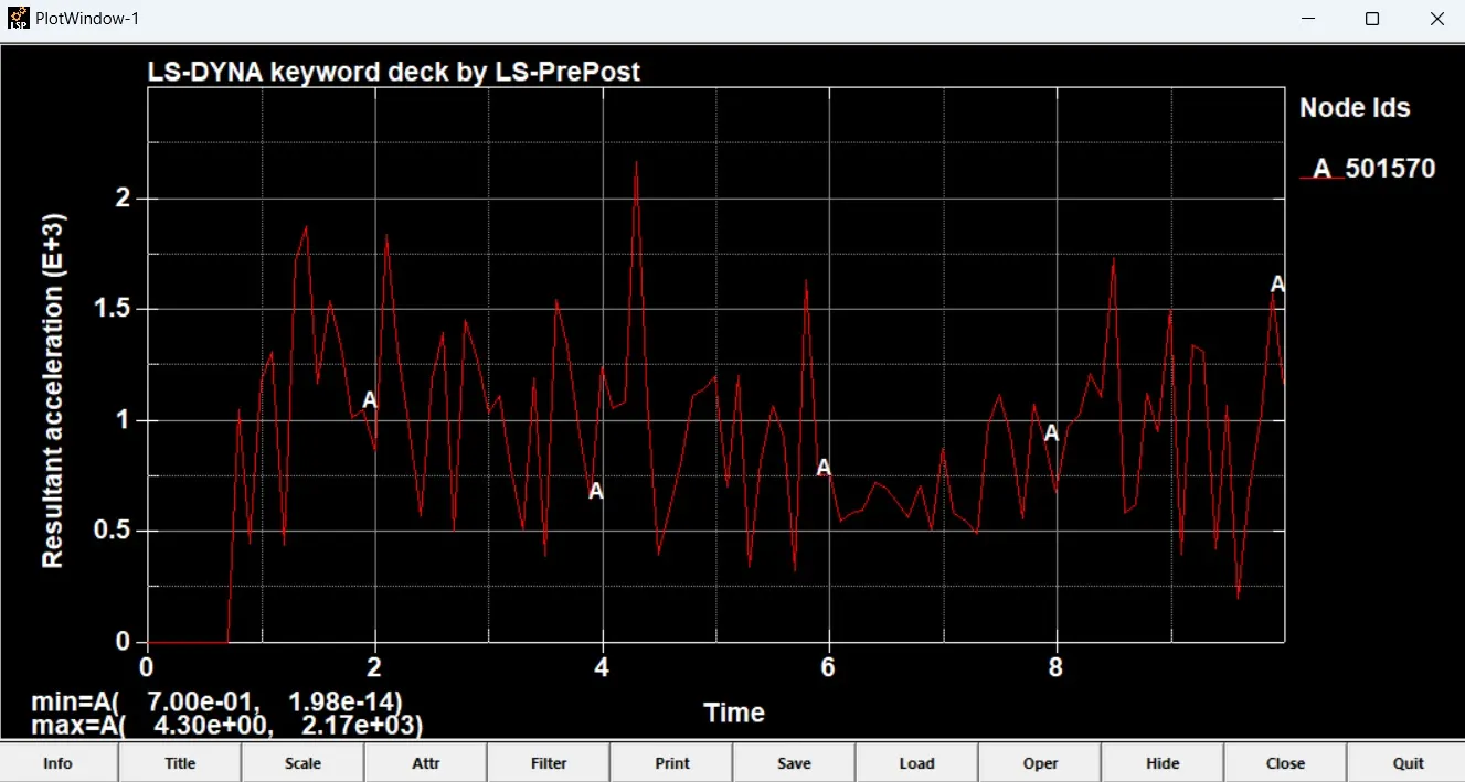
Acceleration Plot (Node)
Acceleration plot for the node of Beam Spotweld
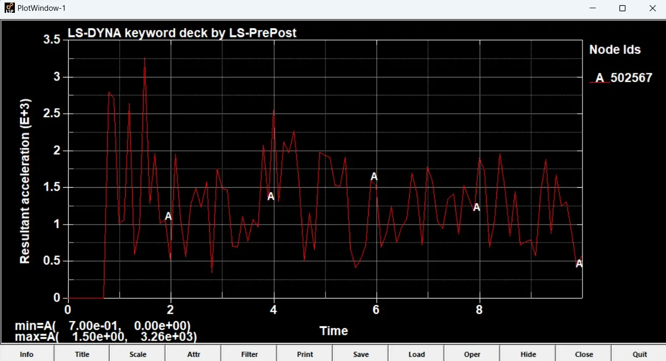
Acceleration plot for the node of Hexa Element Spotweld
Directional Stress and Strain
For Spotweld Beam Element
Maximum stress in X direction = 3.542e+02
Maximum stress in Y direction = 3.266e+02
Maximum strain in X direction = 0
Maximum strain in Y direction = 0
For Spotweld Solid Hexa Element
Maximum stress in X direction = 3.516e+03
Maximum stress in Y direction = 1.585e+03
Maximum strain in X direction = 0
Maximum strain in Y direction = 0
Simulation Animation
For Spotweld Beam Element Spotweld
https://www.youtube.com/watch?v=kGZsoz9IvQk
For Solid Hexa Element Spotweld
https://www.youtube.com/watch?v=aKLCF0cMGfM
Conclusion:
Thus we have done spotweld modeling using Beam Element and Solid Hexa Element.