Week 6 - Creating connection for Rear door
Aim: Creating Connections for real door of a passenger car.
Introduuction: A card model has various components and each components is modeld. Each model is meshed seperatly and then assembeld for the analysis. For assembling there is need of Connections between the models. The connections are of diffwerent type and done in ANSA.
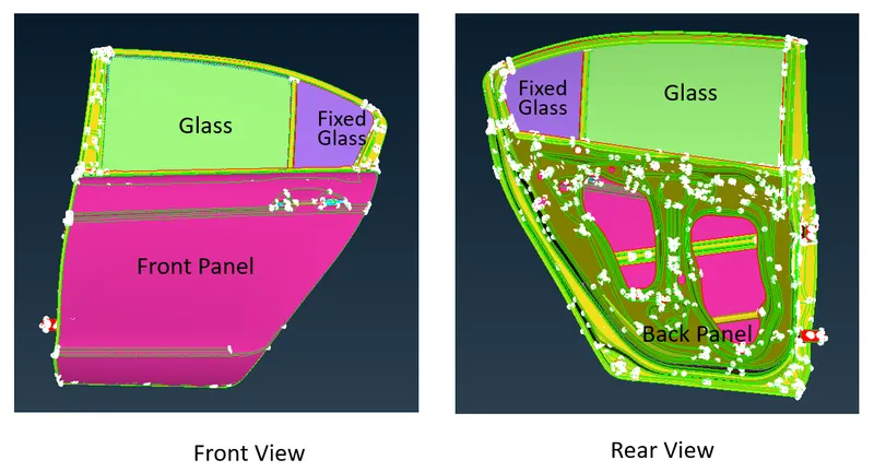
Generally, Process of connection is divided into two parts:
1. First create a ANSA entities, containing information such as types, position, parts to connected and geometry.
2. Realized (Convert to FE representation) already created entities.
Types of Connections:
1. Rigid
a) RBE2 (two node and multi node)
b) RBE3 (two node and multi node)
2. Seam Weld
a) Y joint weld : For perpendicular surfaces
b) Overlap weld : For parallel serfaeces
3. Cbush Element: Use to lock air, water
4. Spot weld
5. Bolt
Steps to create different connections:
Bolt Connection:
1. We have to create a 3d point.
2. We have to convert the 3D point to a bolt.
3. We have to use the connection manager and we have to select it.
4. We have to select the PID’s(P1,P2etc..)
5. Fe representation - Bolt
6. We have to provide the Search distance.
7. Say apply and realize it.
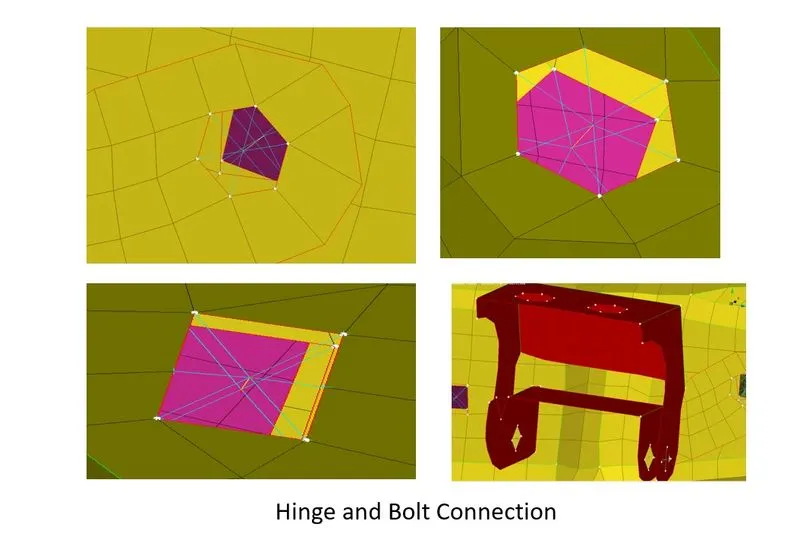
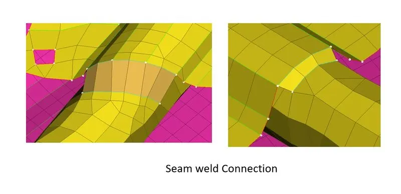
Seam weld Connection:
- We have to create a curve by using the feature2 curve(Mesh>Perimeters>Feat2Curve) option.
- We have to convert the curve to a seam line.
- We have to use the connection manager and we have to select it.
- We have to select the PID’s(P1,P2)
- Fe representation - Overlap Shell (For Parallel Surfaces) or Y-joint Shell ( For Perpendicular Surfaces)
- We have to provide the Search distance.
- We have to choose the Proper base sheet.
- We have to provide the width value as the target element size.
- We have to create the weld pid.
- Say apply and realize it.
Spot weld Connection:
- We have to create a 3d point.
- We have to convert the 3D point to spot weld point.
- We have to use the connection manager and we have to select it.
- We have to select the PID’s(P1,P2)
- Fe representation - Rbe3-Hexa-Rbe3
- We have to provide the Search distance.
- We have to create the weld pid.
- Say apply and realize it.
CBush Connection:
- We have to create a curve by using the feature2 curve(Mesh>Perimeters>Feat2Curve) option.
- We have to convert the curve to a spot line.
- We have to use the connection manager and we have to select it.
- We have to provide the Spacing value.
- We have to select the PID’s(P1,P2)
- Fe representation - Rbe3-CBush-Rbe3
- We have to provide the Search distance.
- We have to create the Bush pid.
- Say apply and realize it.
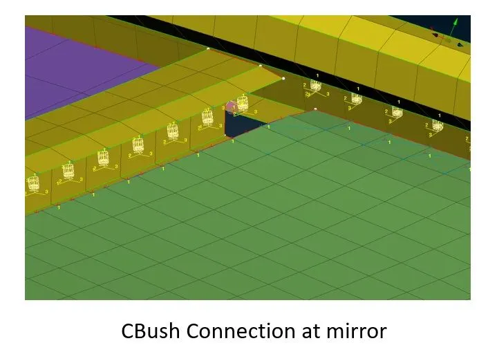
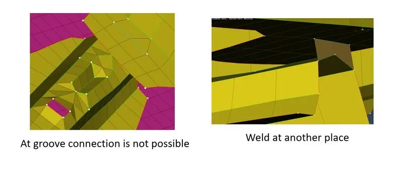
Note: At grove it is difficult to creat any connection, so we find a proper place to connect it.
Difference bwtween RBE2 and RBE3:
RBE2 has master node at center and slave nodes at Corners while RBE3 has slave node at center and MAster nodes at corners.
Conclusion:
Thus we create connections at different locations.