Week - 5 - Modelling Spotwelds
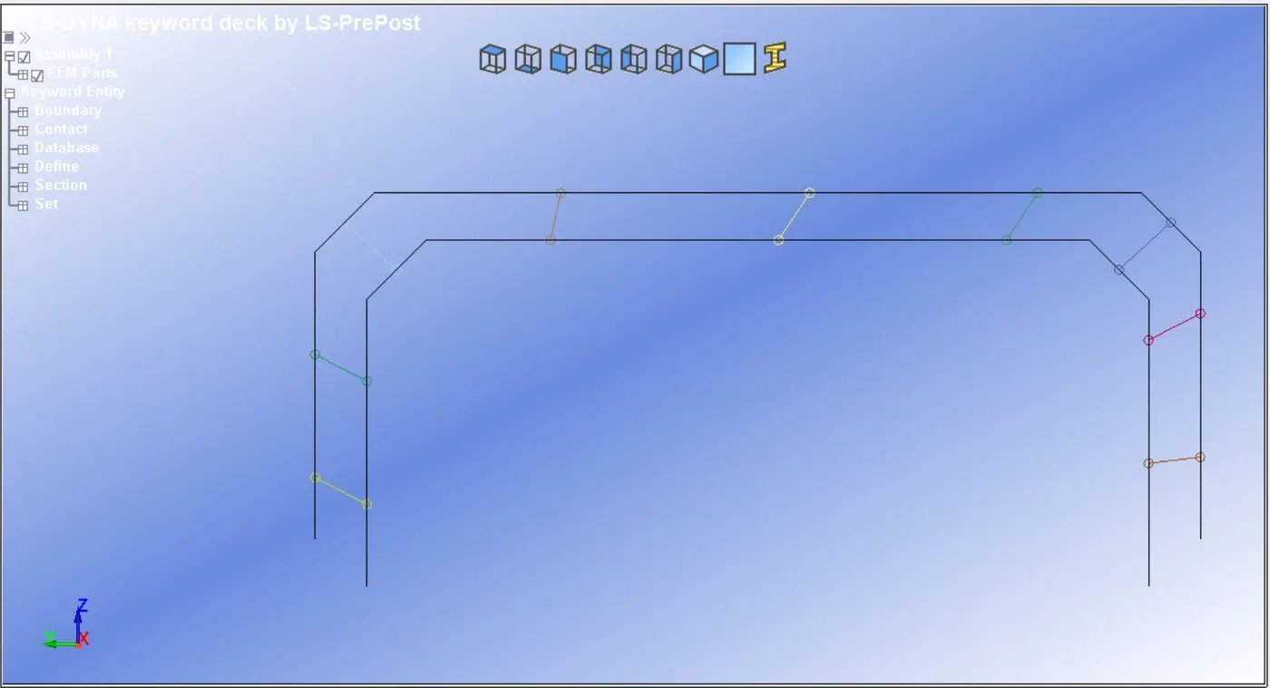
Aim:- In this challenge, we create two types of spot weld one from the beam element and the other from the solid element, and compare them to the given component.
procedure:-
1. Spot weld with beam element:-
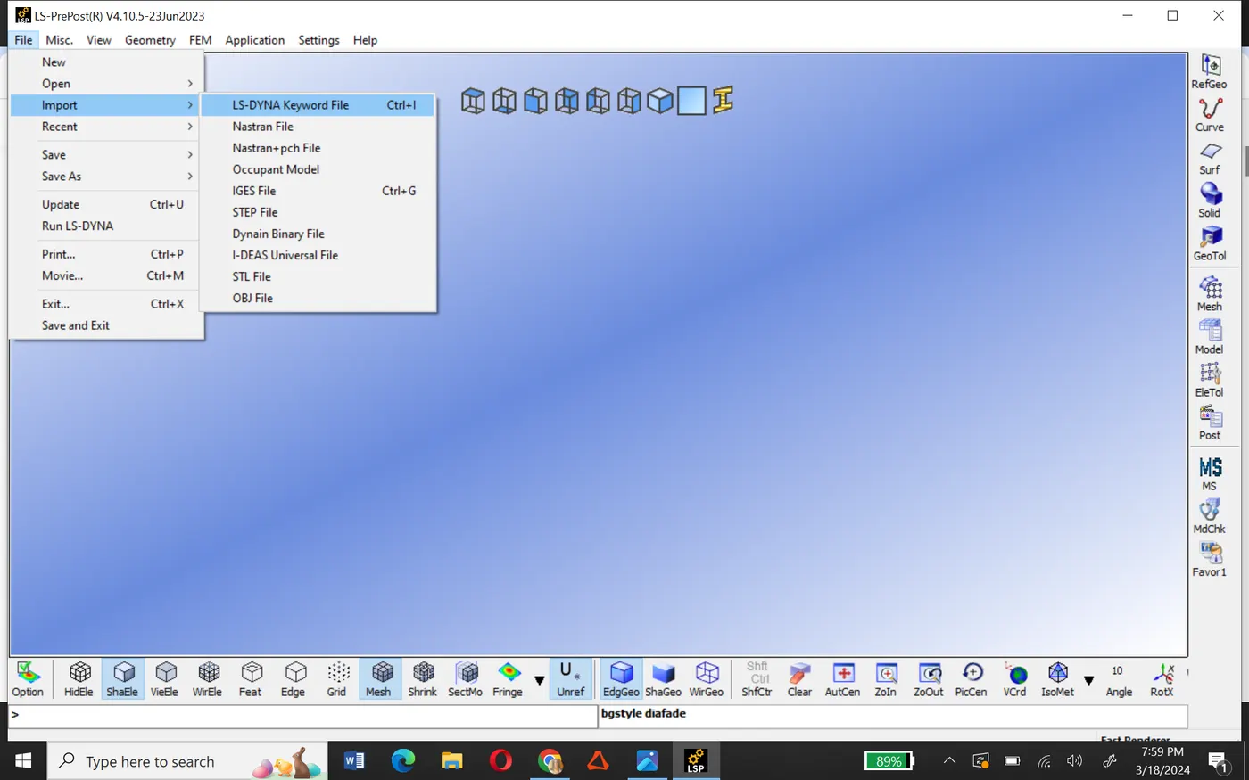
- First open Ls-prepost and import the file here.
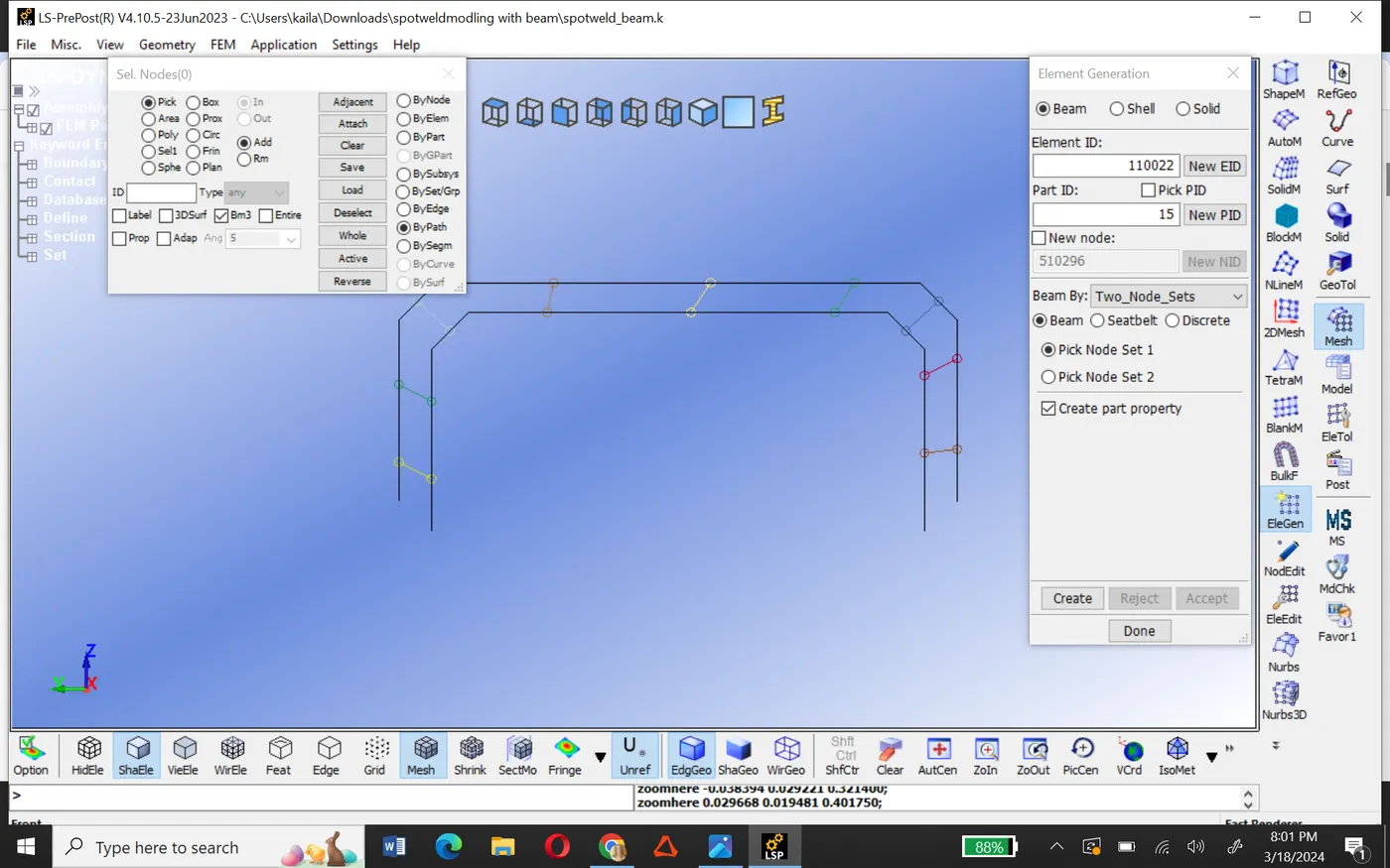
- To create beam element go to mesh>elegen and create the element as shown in below image.
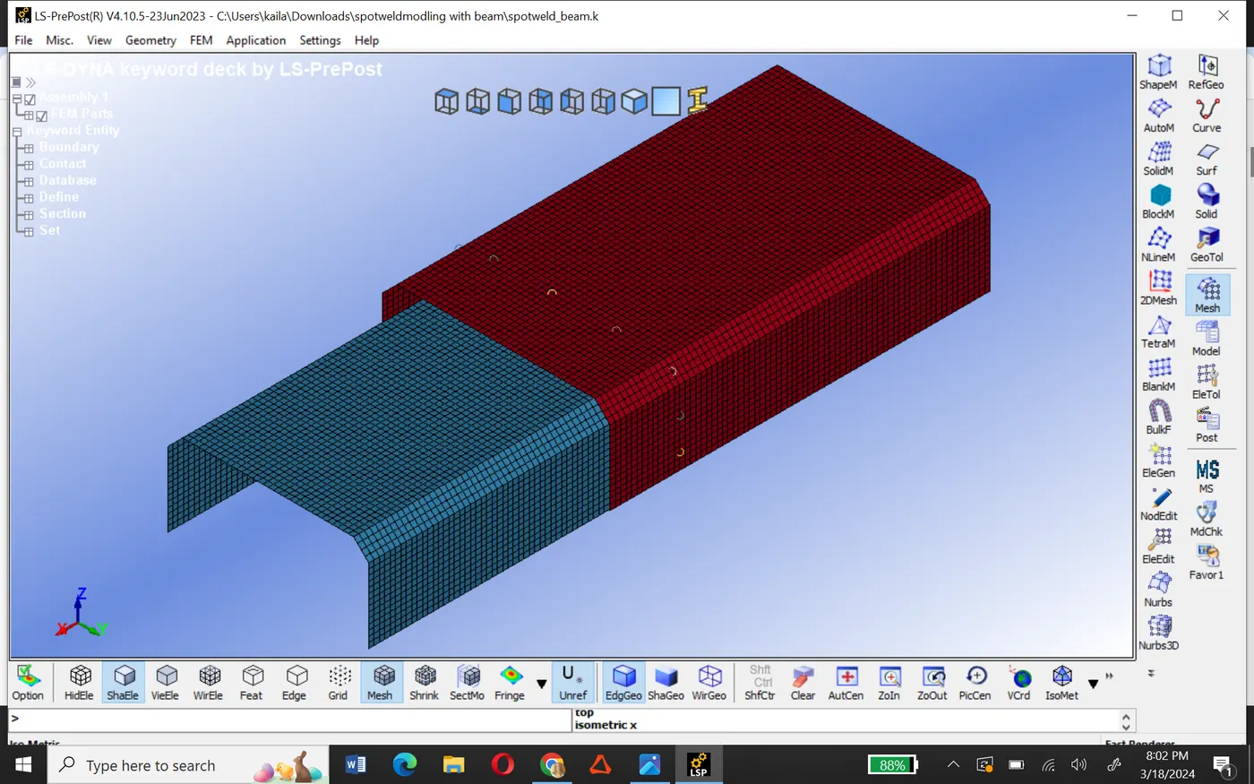
- After creating all beam elements define section ID two different types one shell and the other beam.
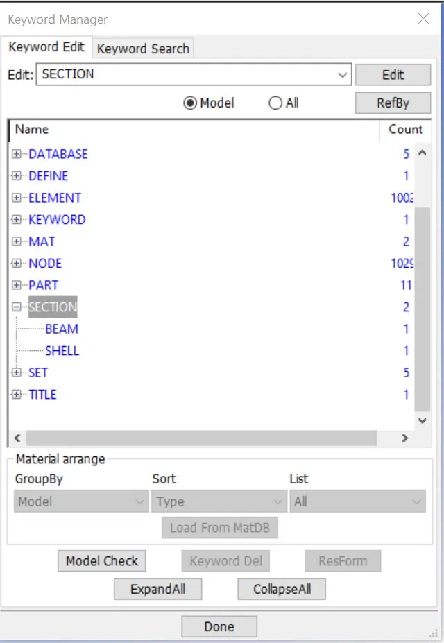
- In beam section element formulation of beam element as 9 which signifies the behavior of spot weld as beam element.
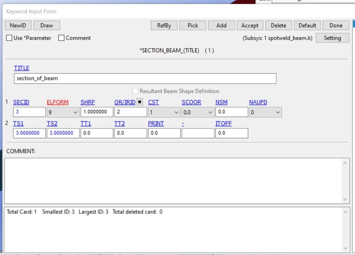
- Then create material properties both for weld and shell parts.
- Material property of the weld parts.
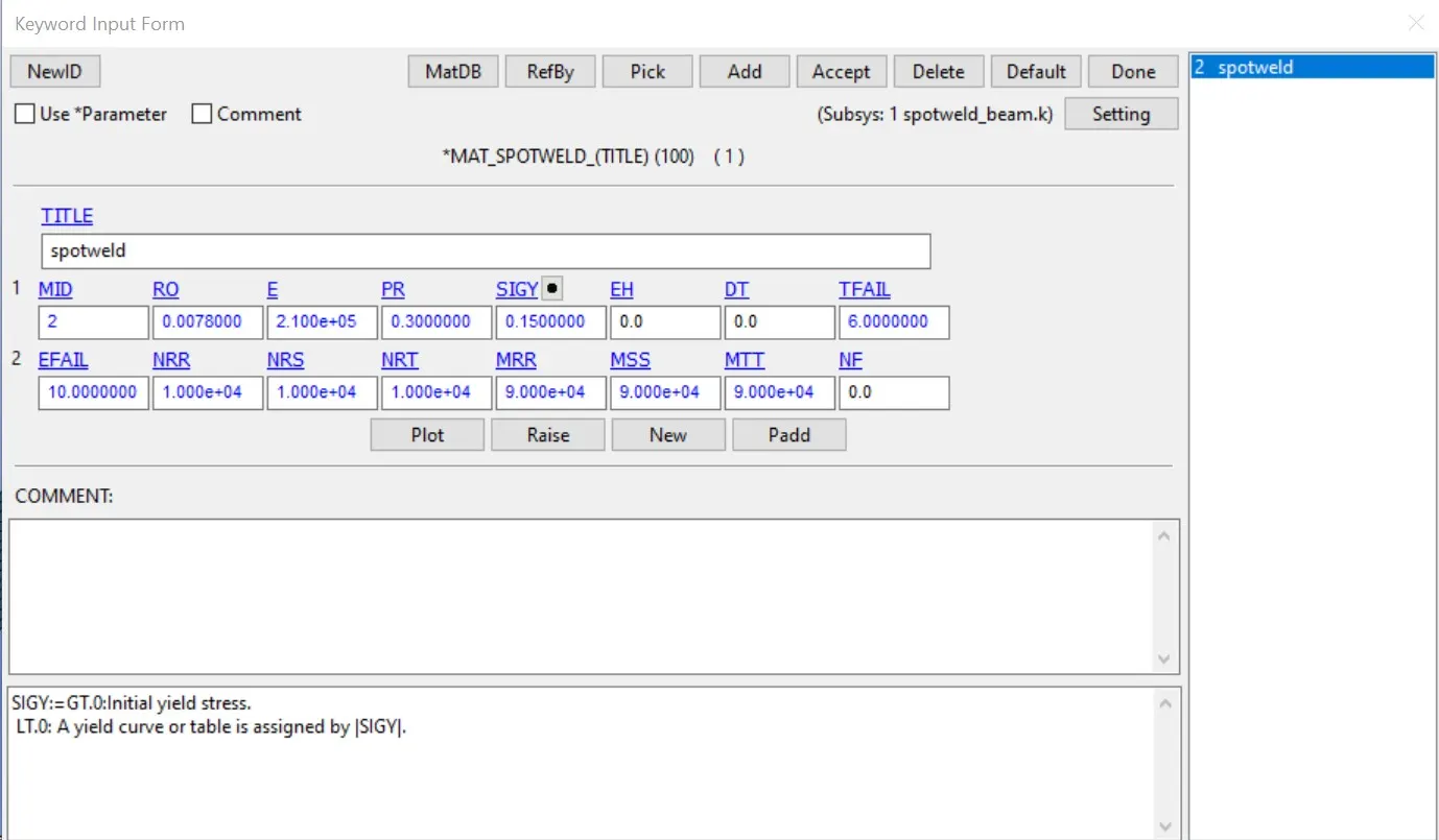
- Material property of the shell parts.
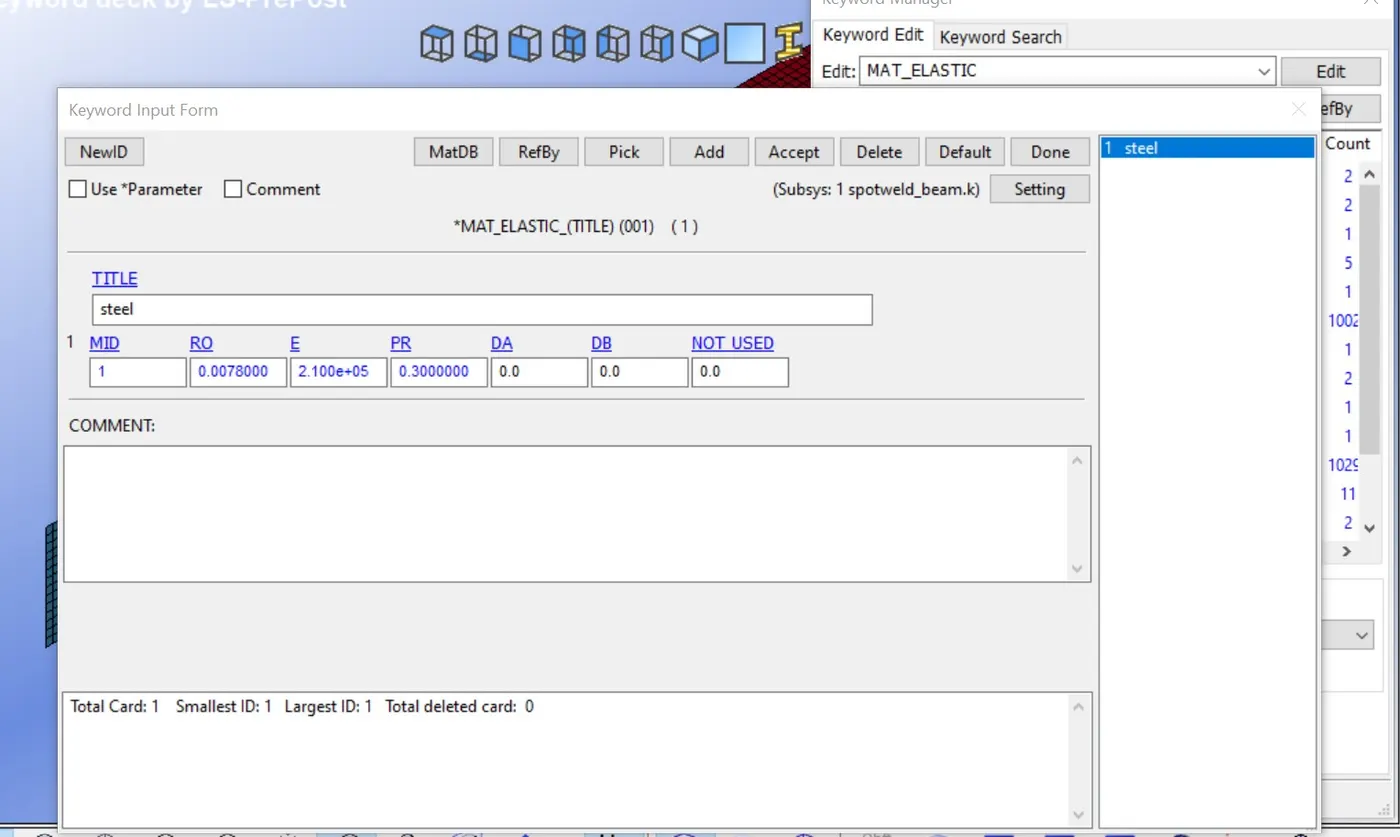
- Now assign all the respective material properties to the part ID and beam.
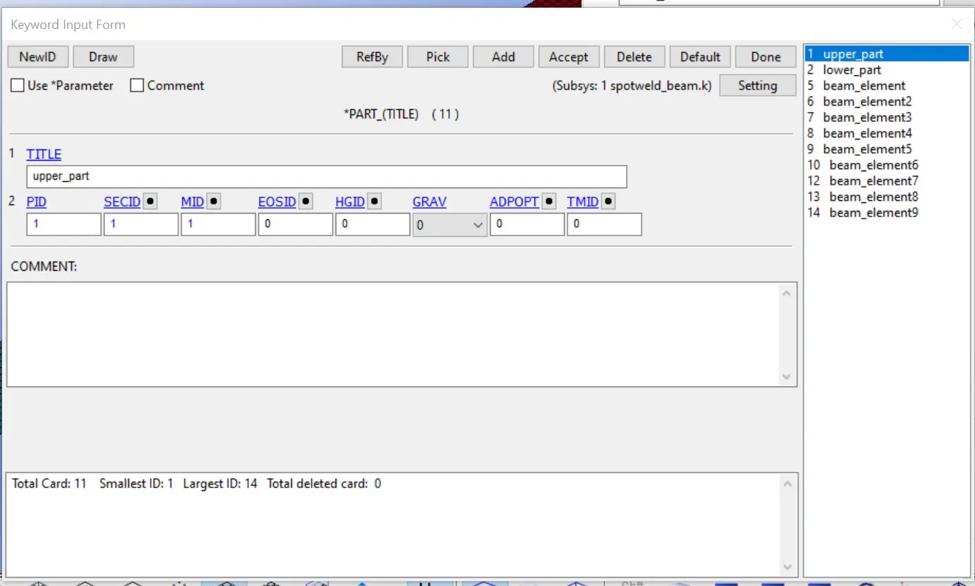
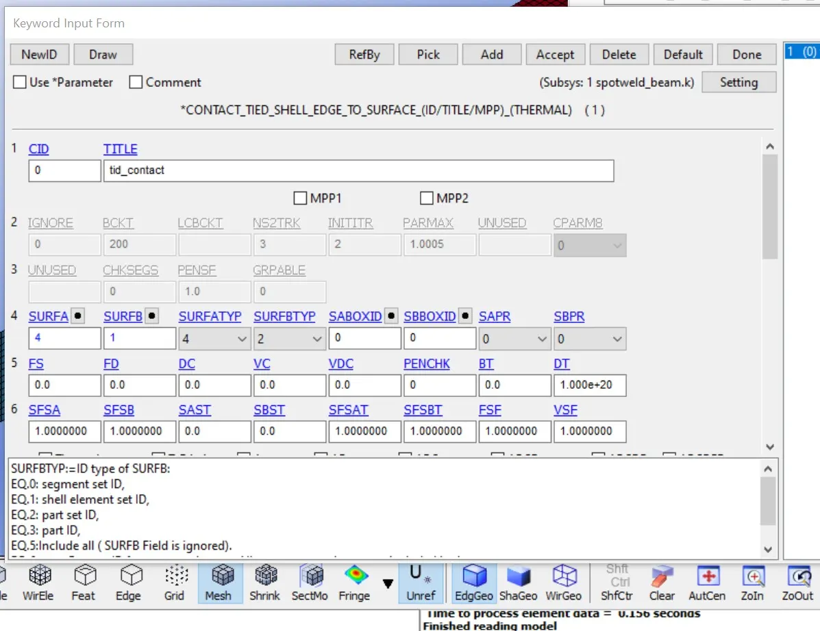
- Then we have to define contact cards for the shell for auto single surface contacts and one for the spot weld element which is a tied shell edge-to-edge contact card.
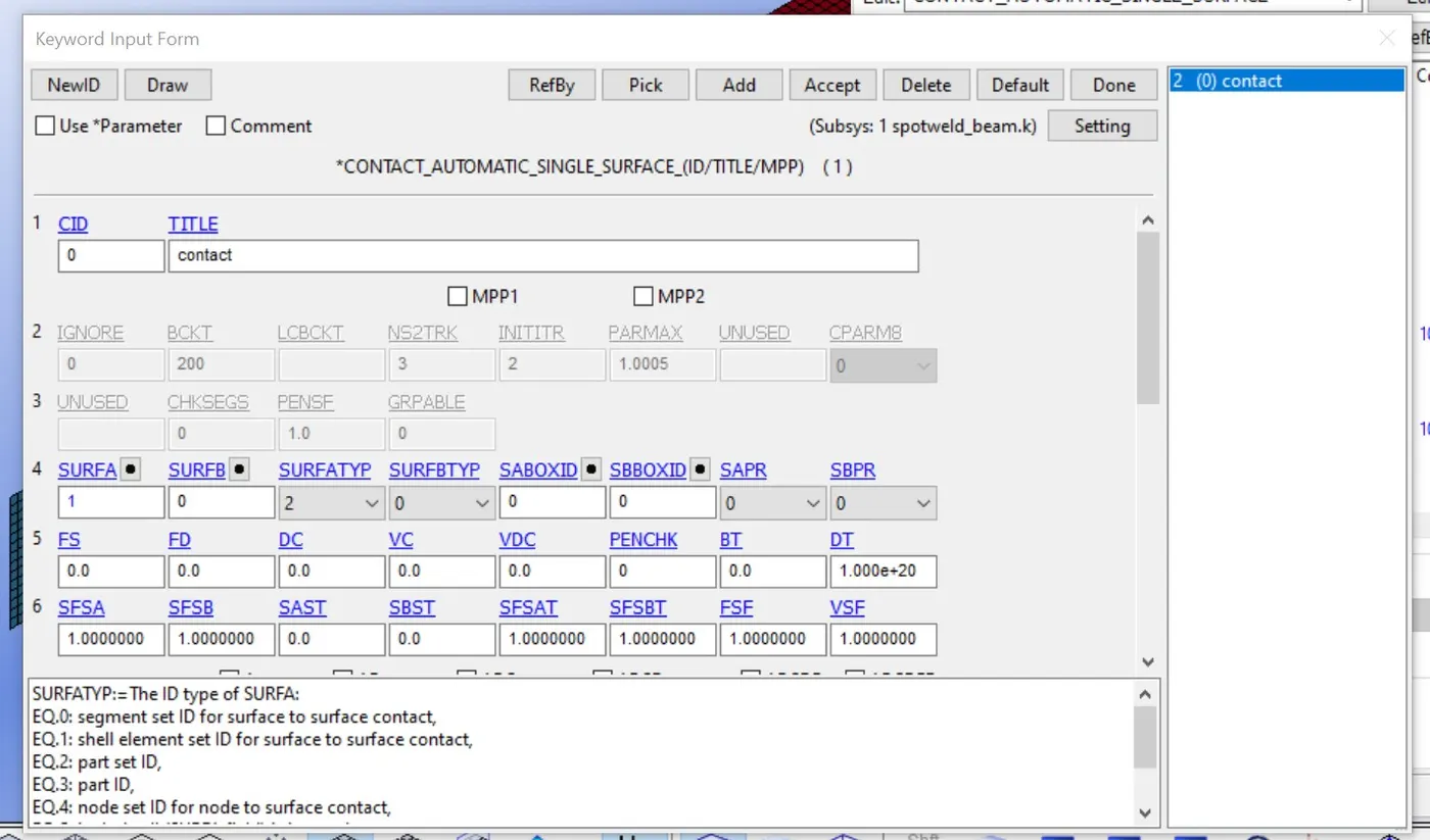
- in auto single surface contact we need only to define slave which is set as a part for the shell.
- in tied shell edge-to-edge contact card the slave card is given as a node set of spot weld beam elements and a master card is given as a part set of shell parts set for shell part.
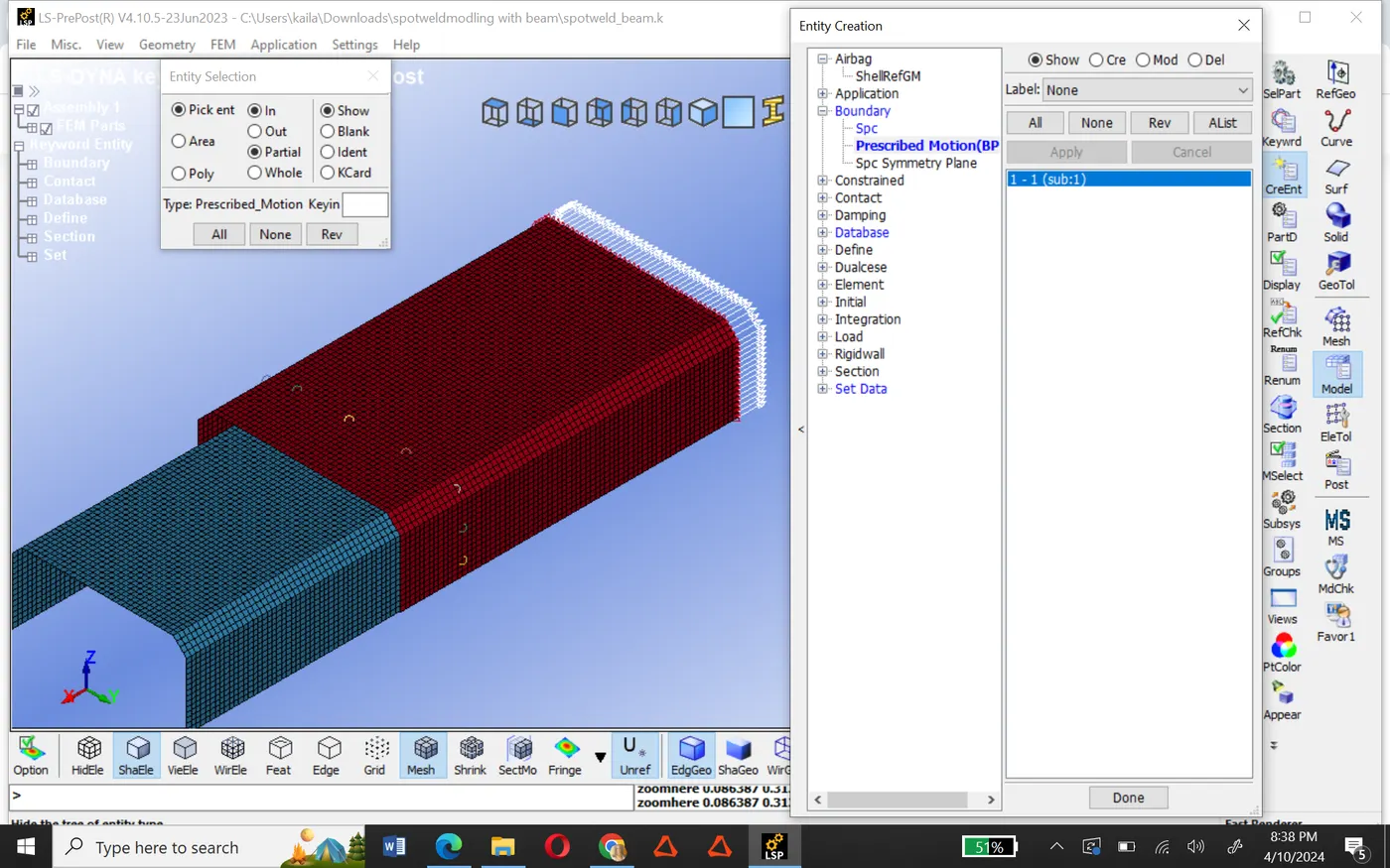
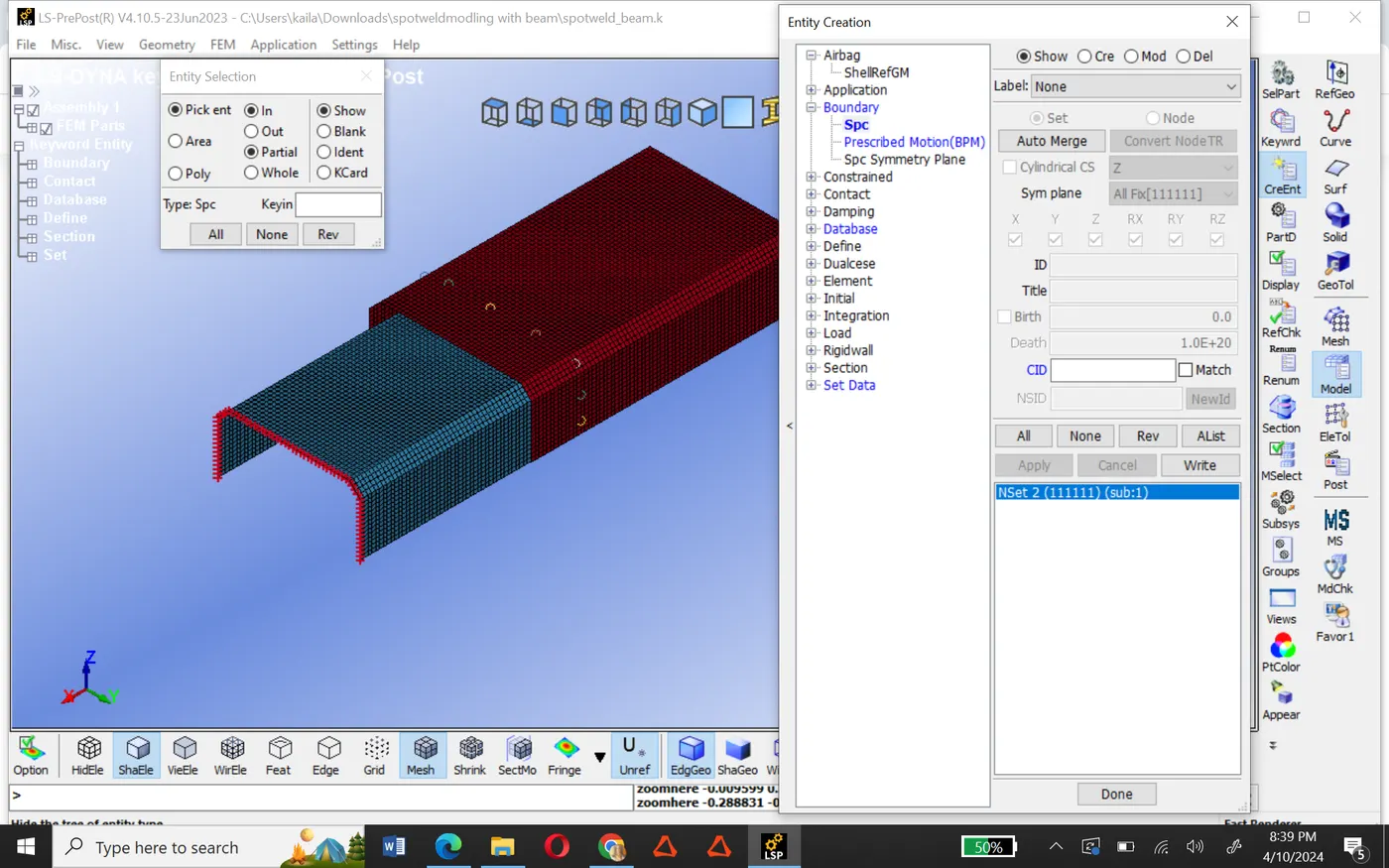
- Now we define boundary conditions like prescribed motion set for displacement and spc set (single point constrained) for fixed.
- After that we define the curve for displacement.
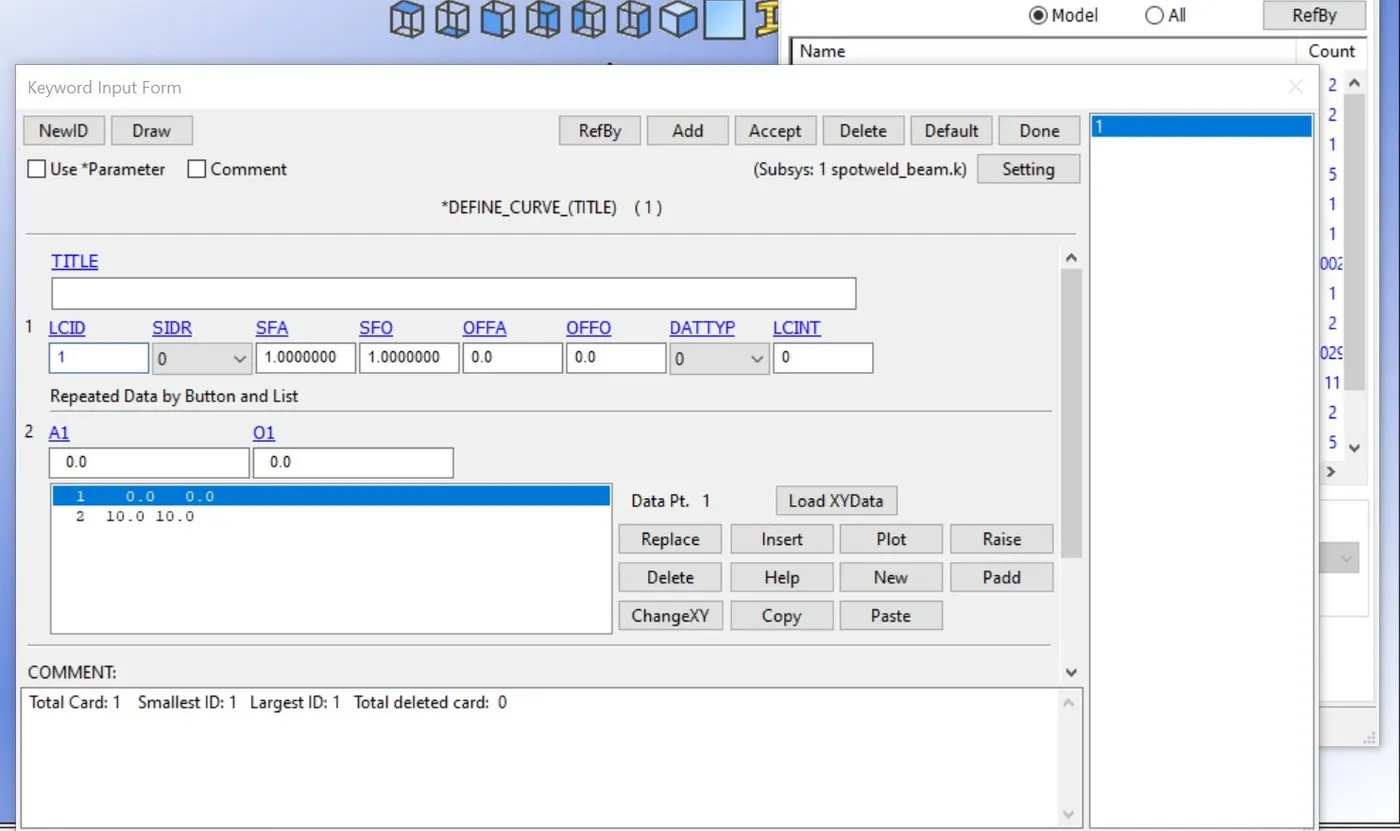
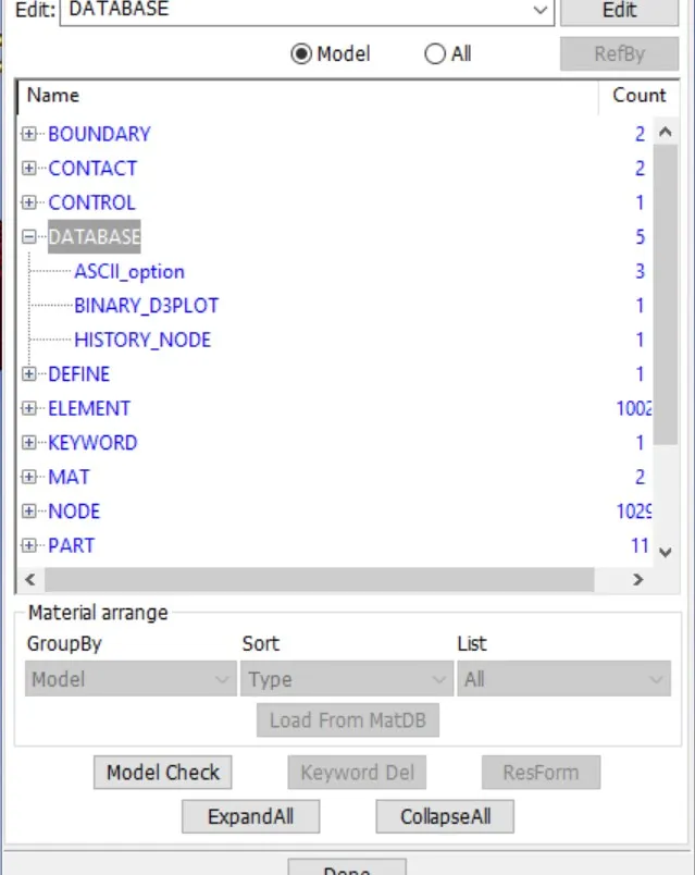
- Then define the database like ASCII, binary d3plot, and history node.
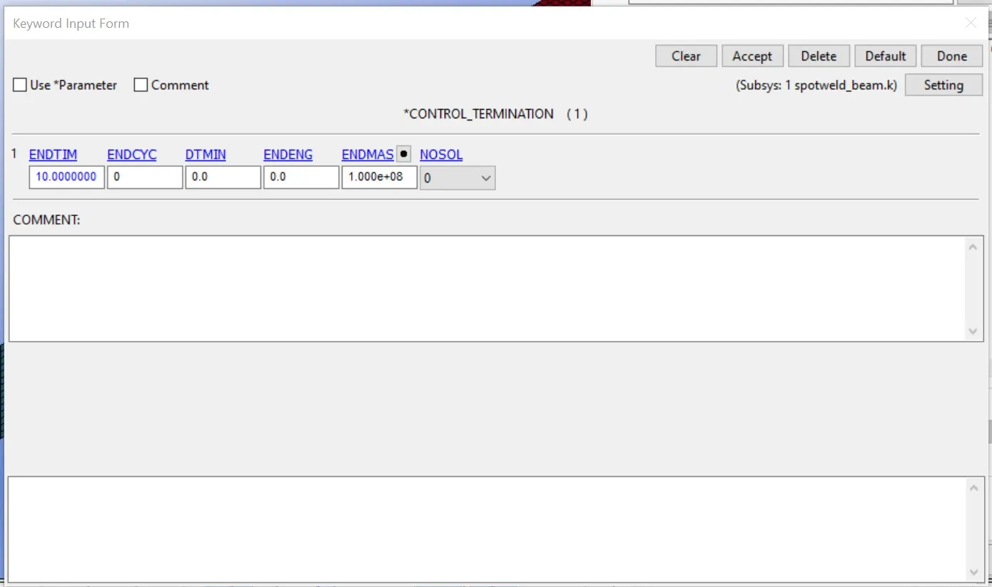
- now define termination with 10ms.
Post-processing(result):-
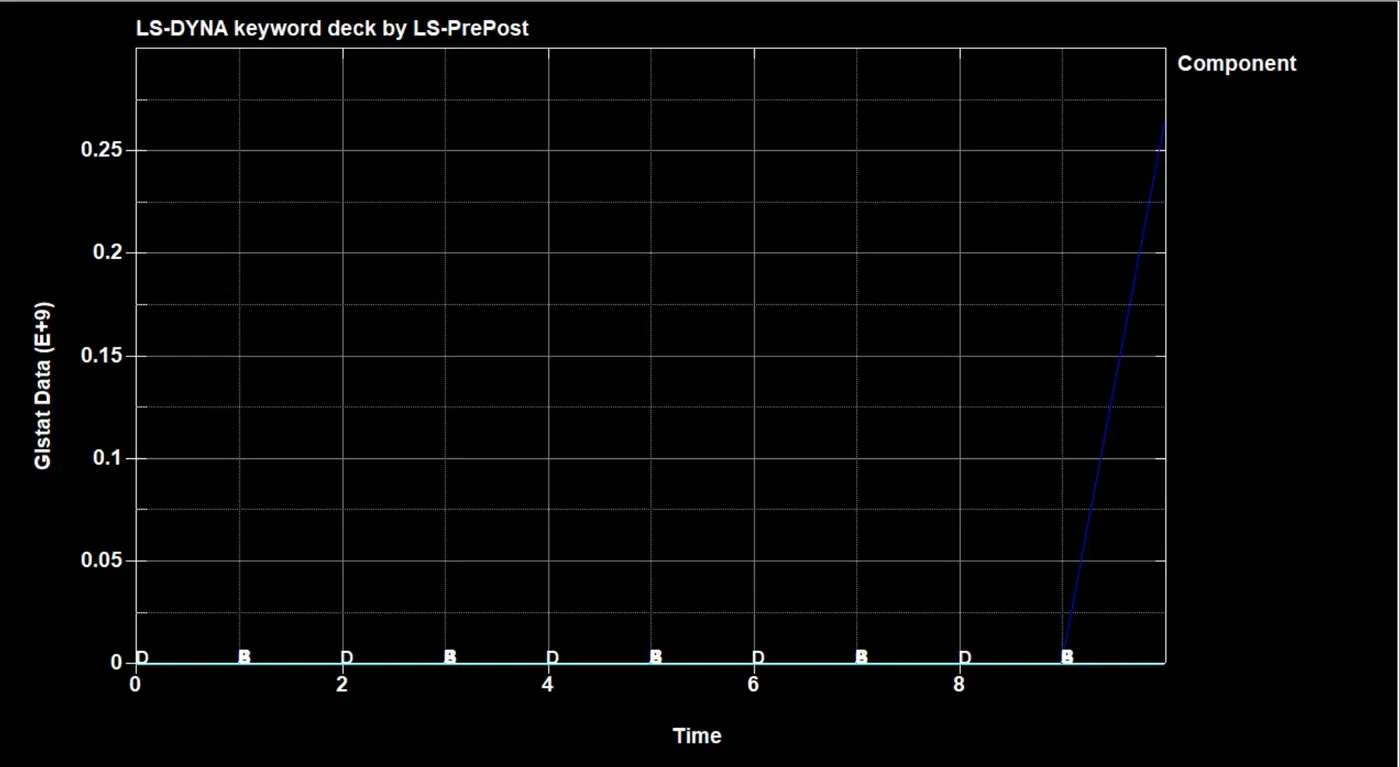
- plot for all energies (total, internal, kinetic, sliding)
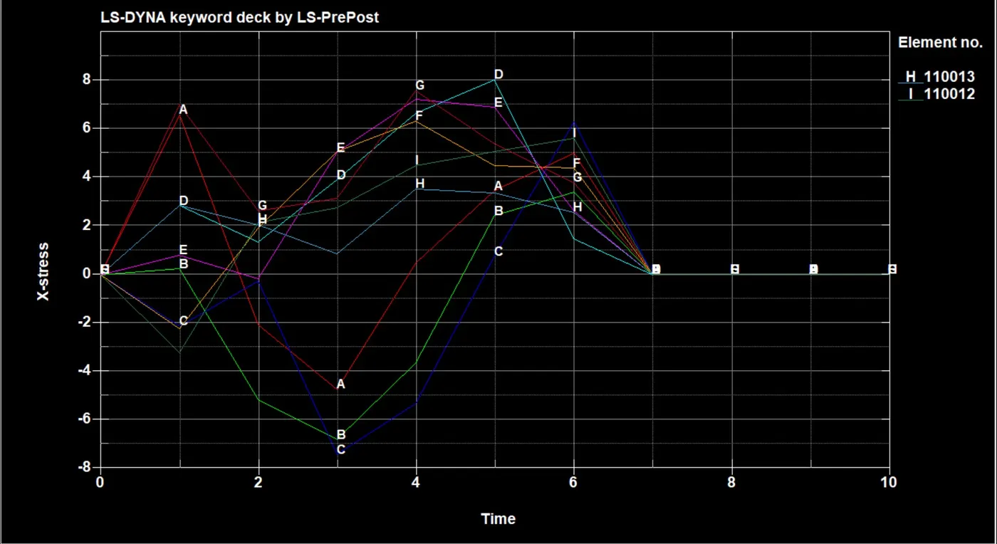
- Maximum directional stress along the length crash box.
- X -stress to the beam element.
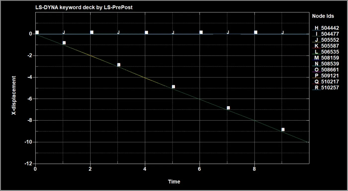
- we can see the displacement of the beam element through the graph. in this graph, some elements show the gradual displacement and some show the shudden displacement.
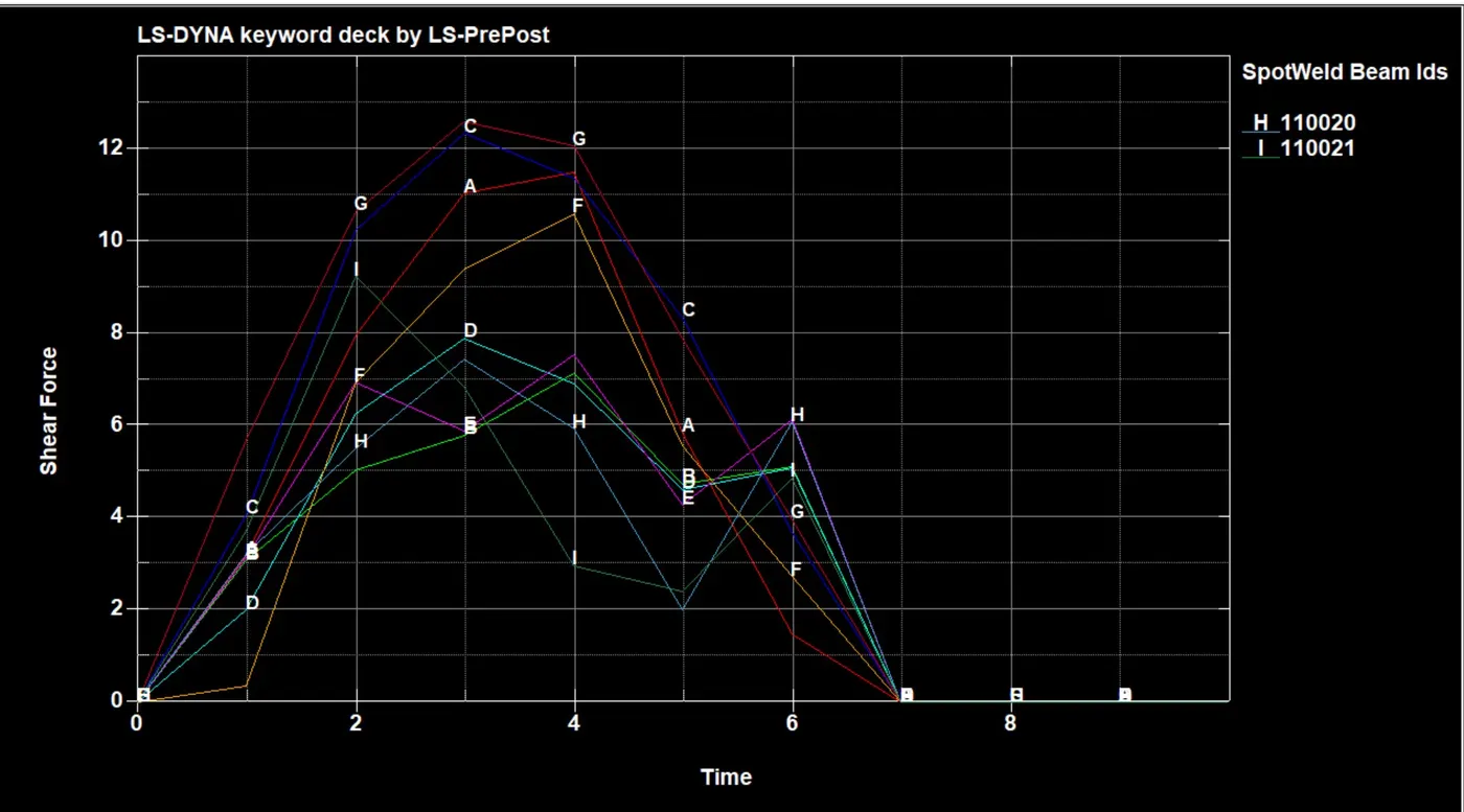
- we can see through the graph shear force for the beam element is high at 12.5 n/mm at 3ms and after 6ms it gradually decreases at 7ms it becomes 0.
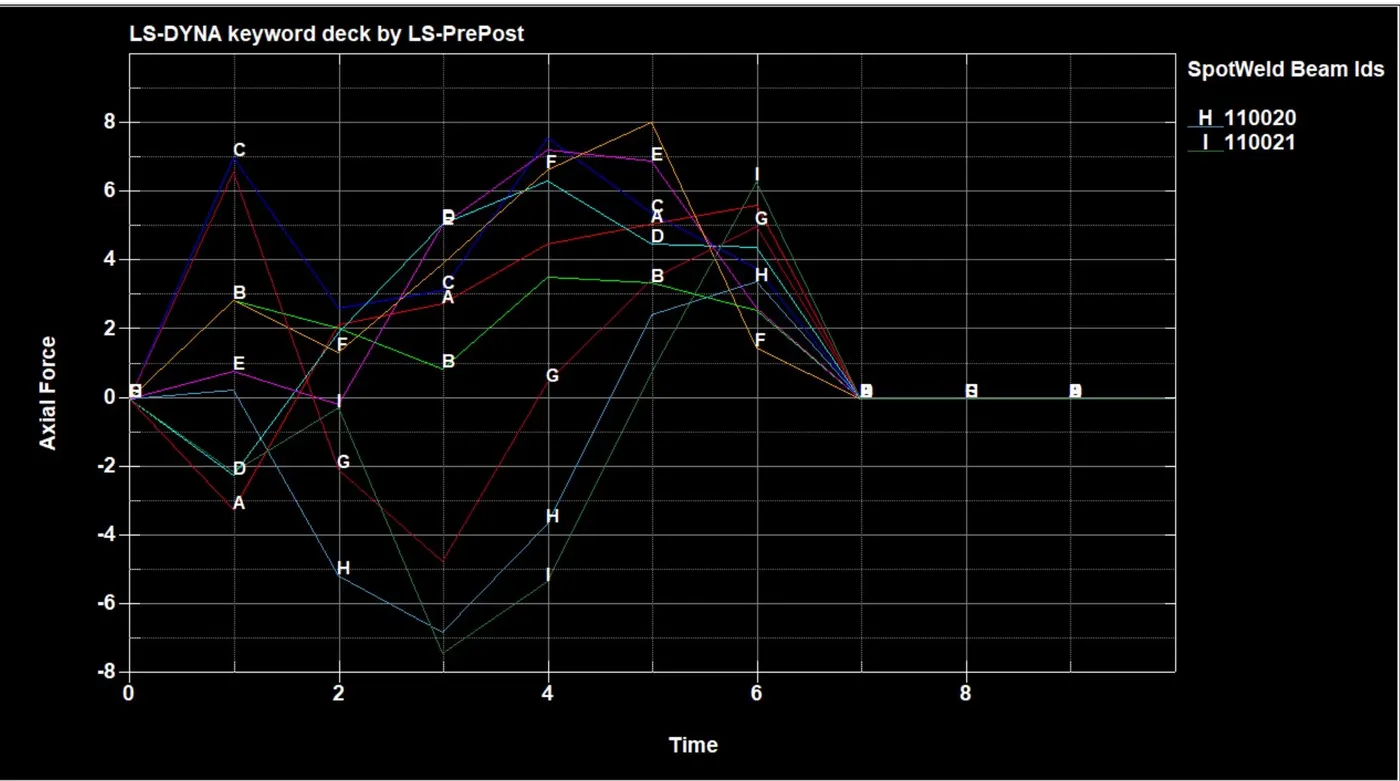
- Axial force generated in the weld of the crass box along the weld length. The highest value of force shown on the F weld (orange line ) is 8n at the time 5ms and after that it rapdly decrease at 7ms all weld brakes.
Spot weld with solid element
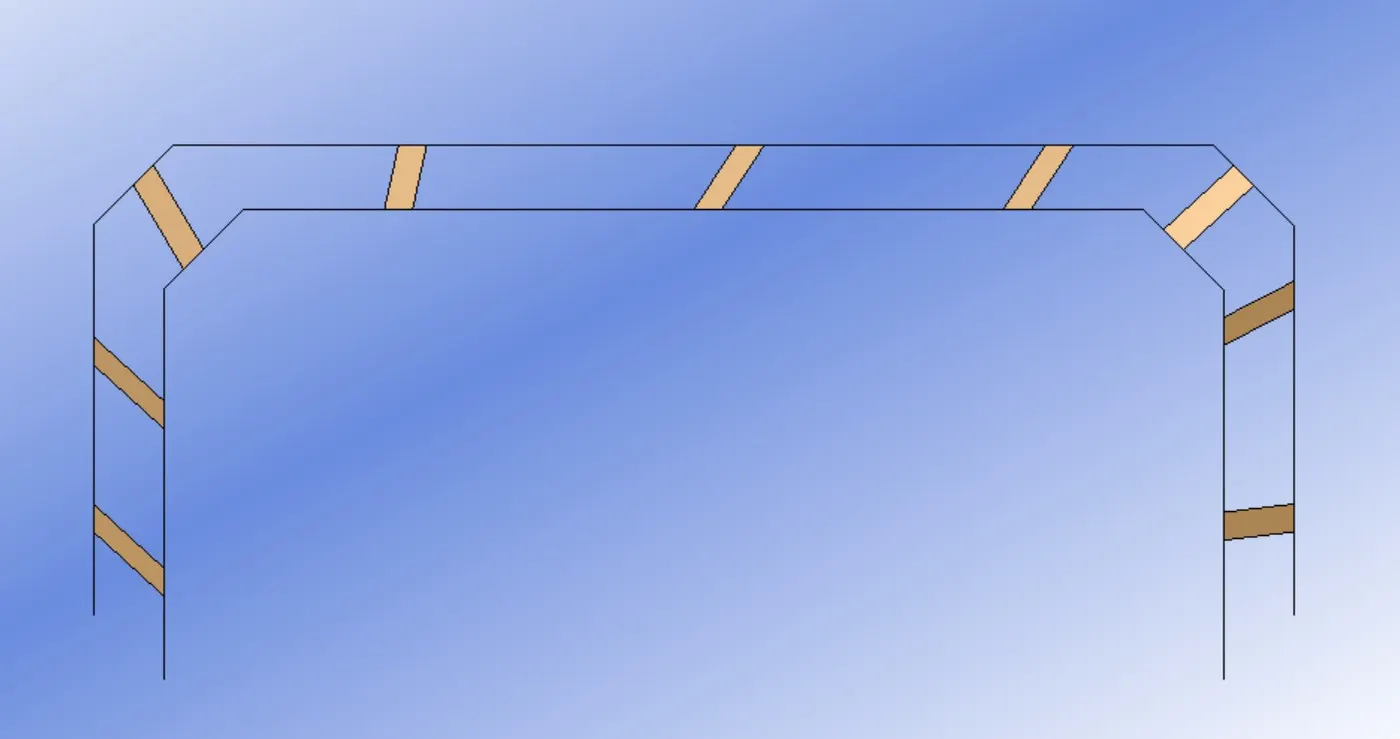
- First create solid elements between two shells using the element edit option. To create the solid elements select four nodes of both opposite shells that the solid element formed.
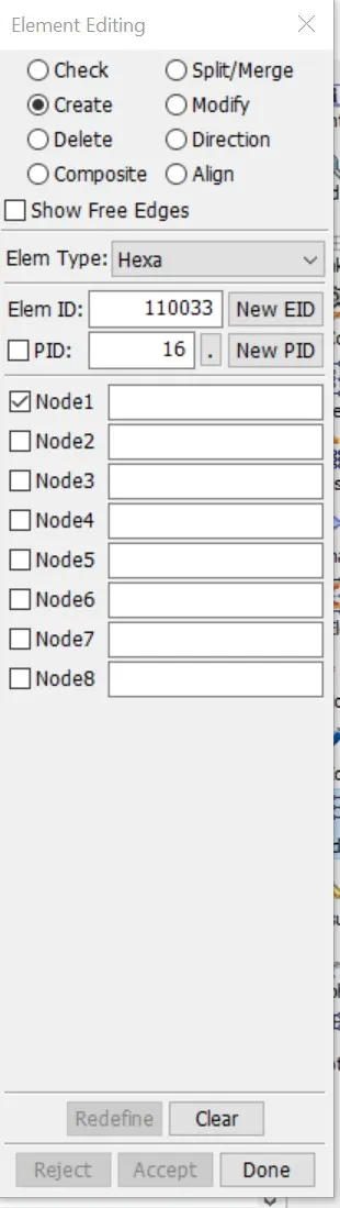
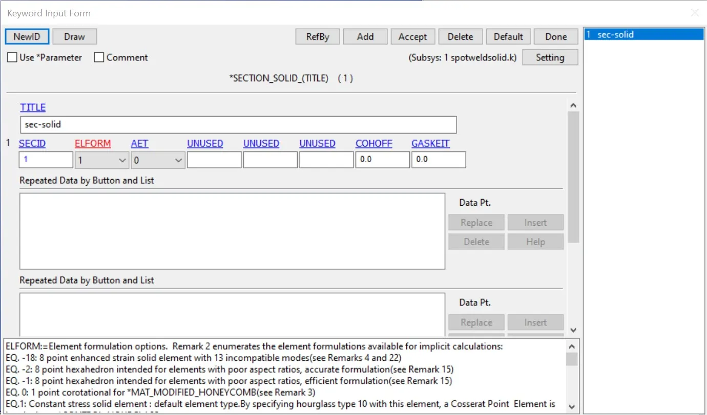
- Next we create a section card for the Hexa element. Here we select ELFORM 1 which is the default for solid elements.
- then we select the material ID for the solid element.
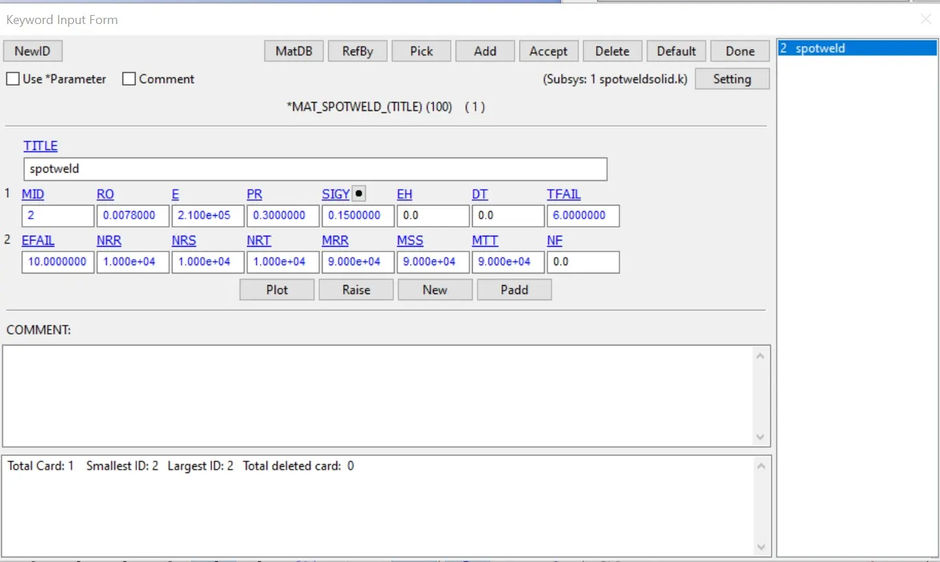
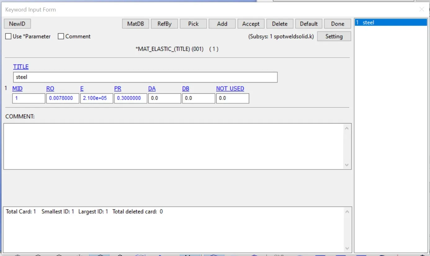
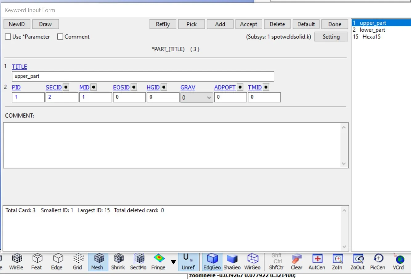
- Now assign the material ID and section ID in the part card.
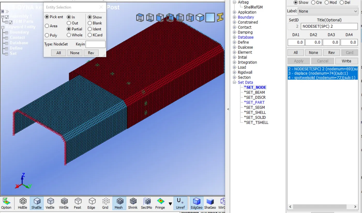
- Now create node-set and part set for all the parts using the entity option.
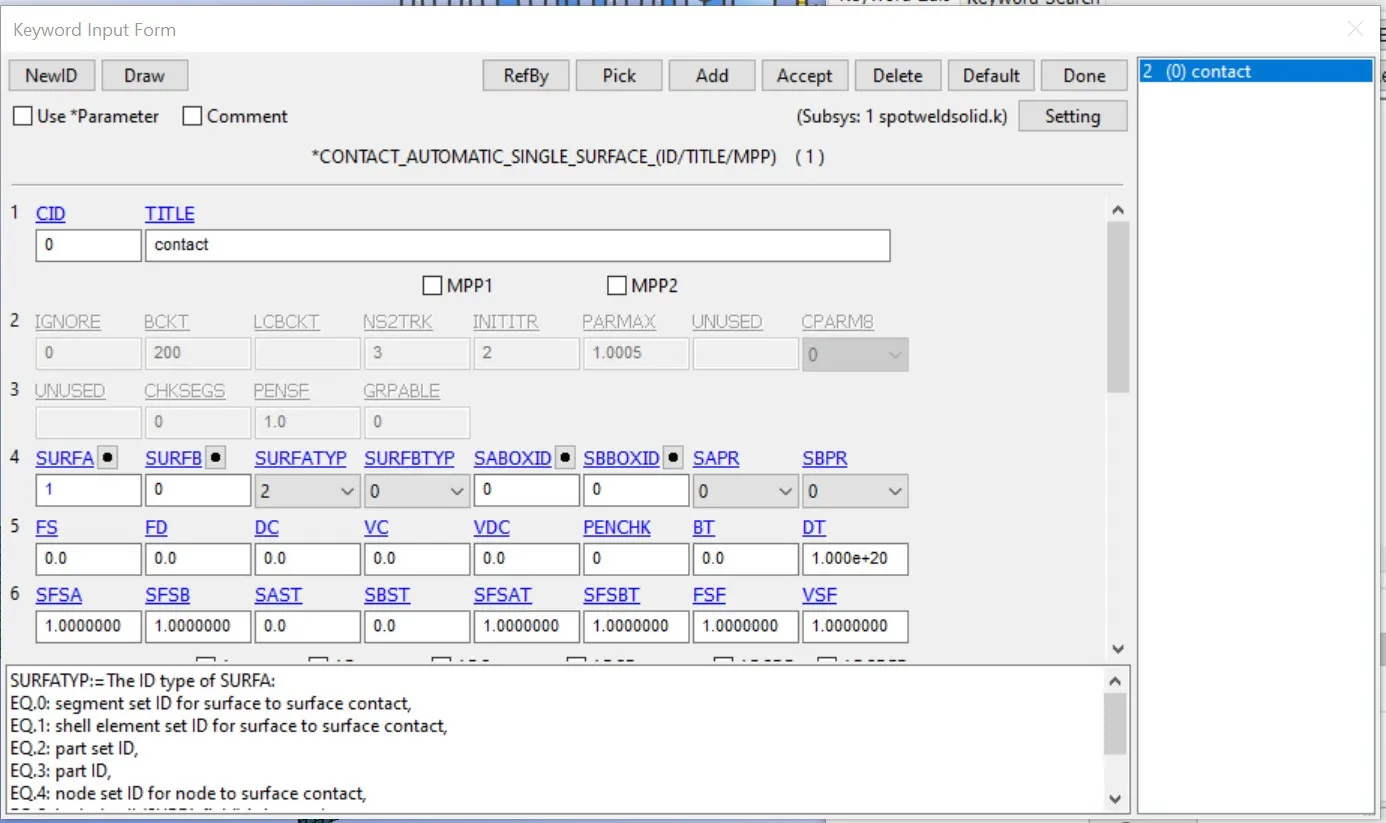
- Now we create a control card that includes an automatic single-surface and select shell part as a slave part.
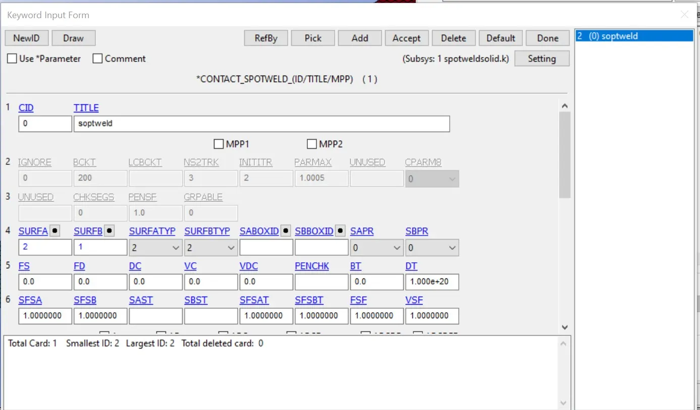
- After that we create a spotweld card and select a hexa element as a slave part and shell as a master part.
- Then define the ASCII data like binary d3plot, historynode.
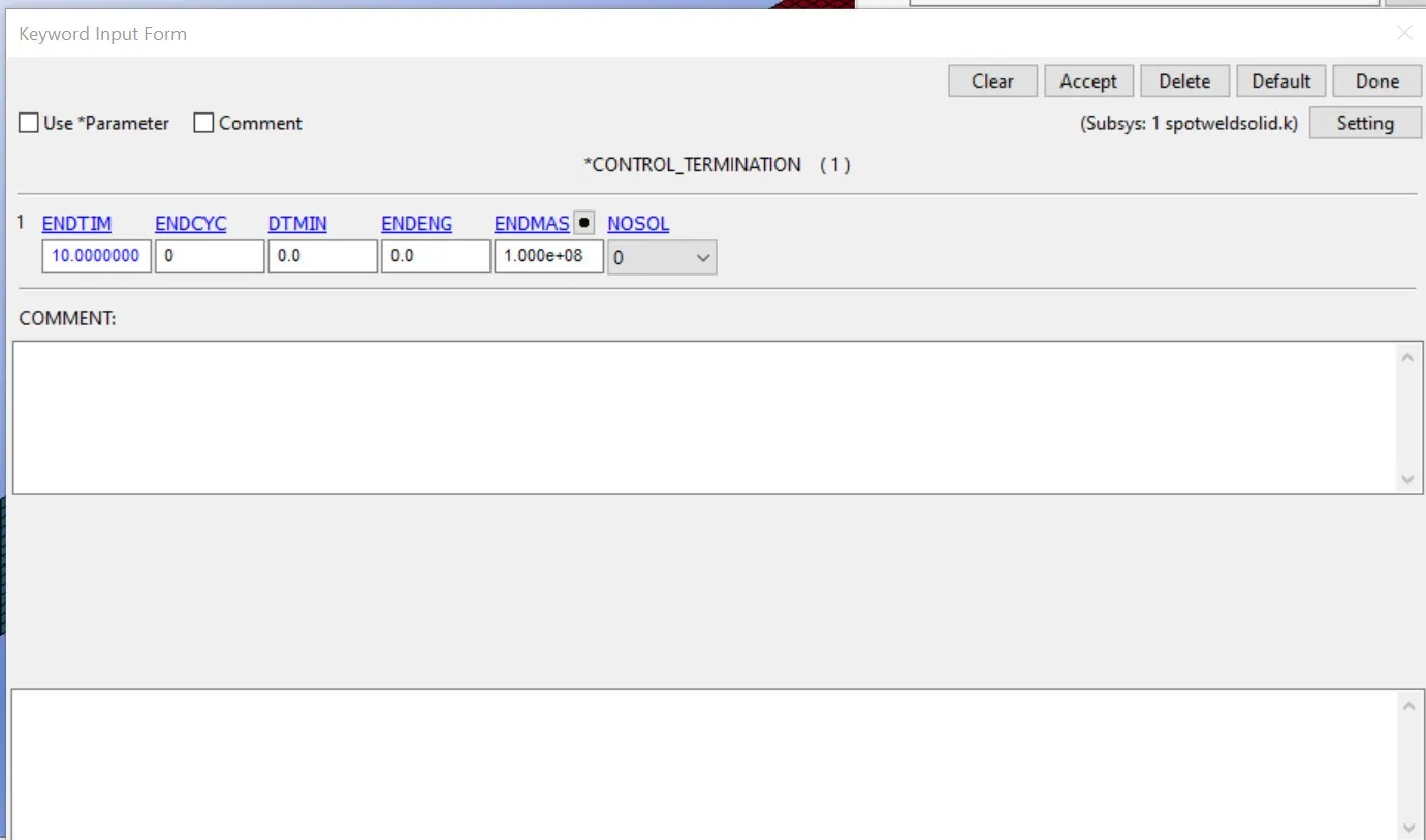
- Then define control termination with termination 10ms.
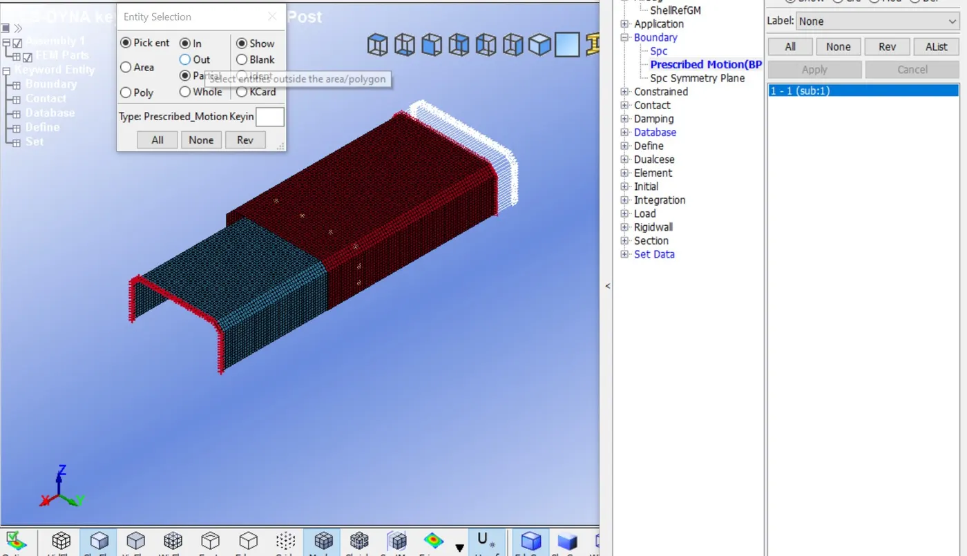
- boundary condition similar to the above case.
Post-processing for hexa weld element:-
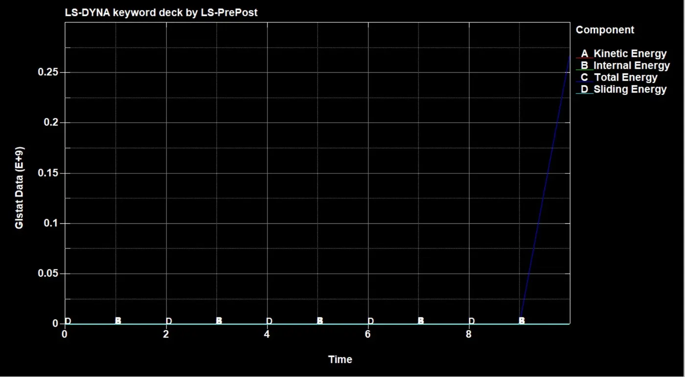
- plot all energies for all parts kinetic, internal, total, sliding.
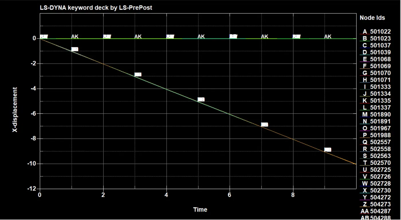
- we can see the displacement of the beam element through the graph. in this graph, some elements show the grasuall displacement and some show the shudden displacement.
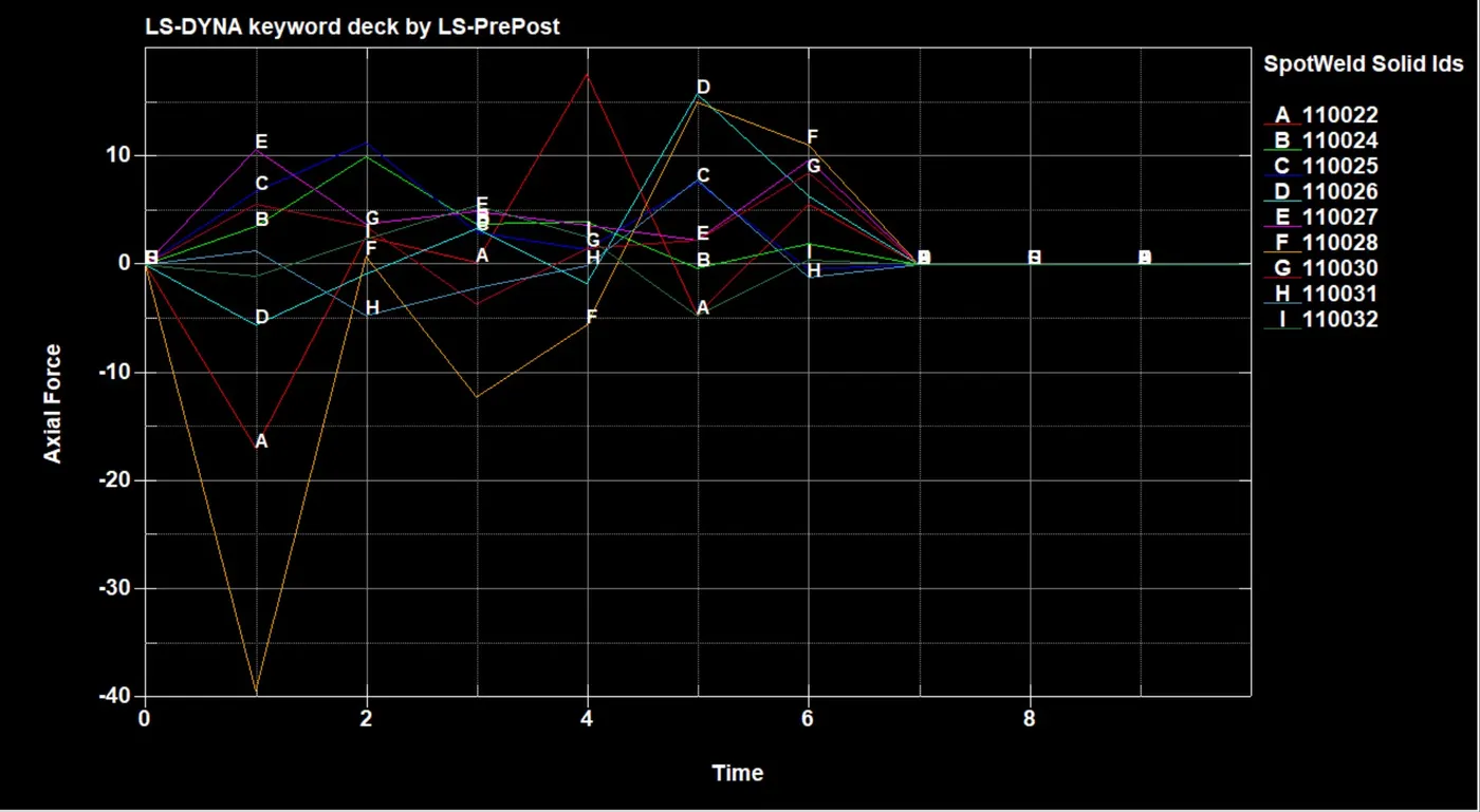
- Axial force generated in the welds along the length. The highest value of axial lode is 25n and after 6ms it's become 0.
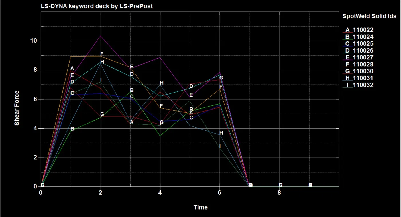
- we can see through the graph shear force valuen for every elements here highest value of shear force is 10.5n/mm and after 6ms it's become 0.
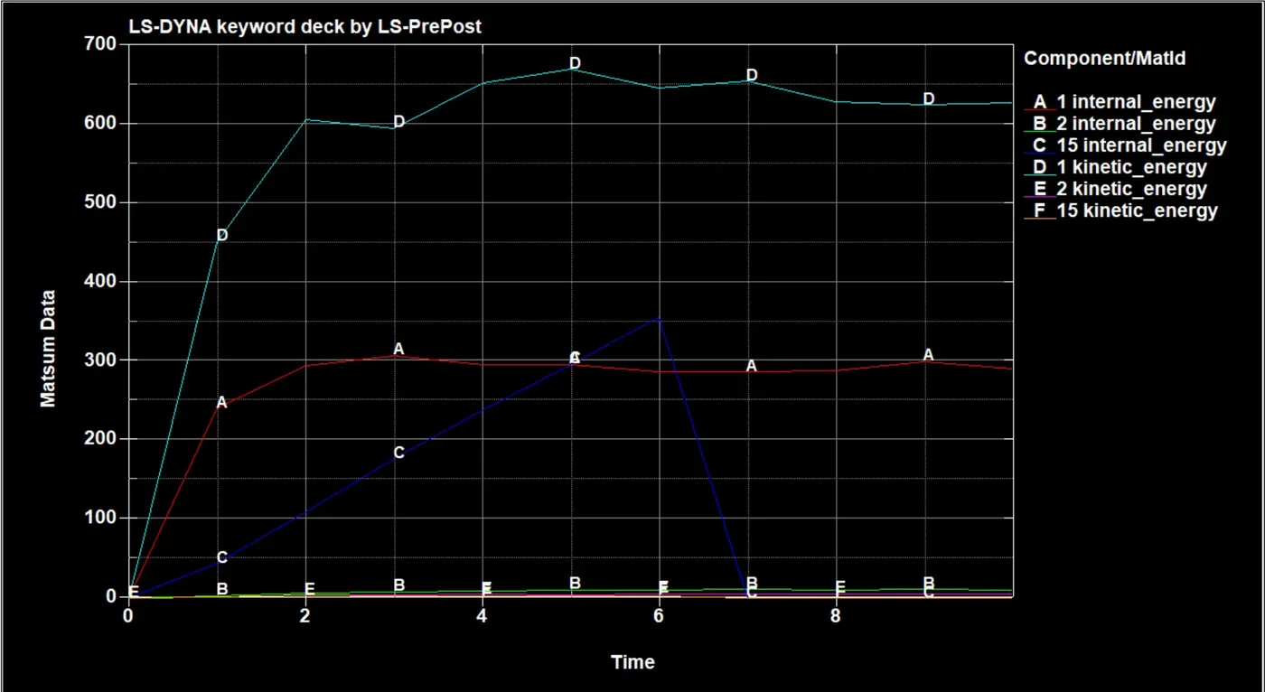
- we see the material energies like internal, and kinetic.
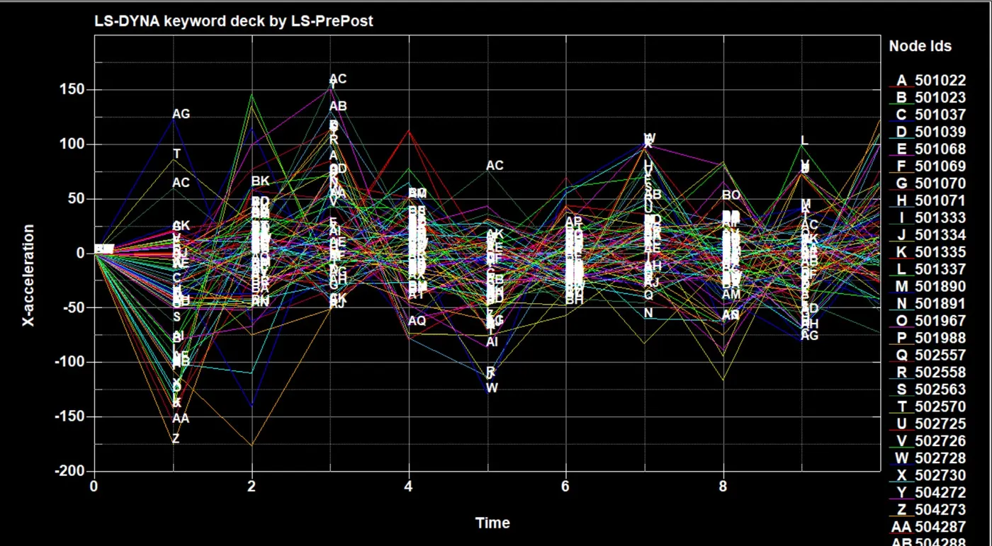
- Acceleration plot for the weld, we can able to plot every node graph.
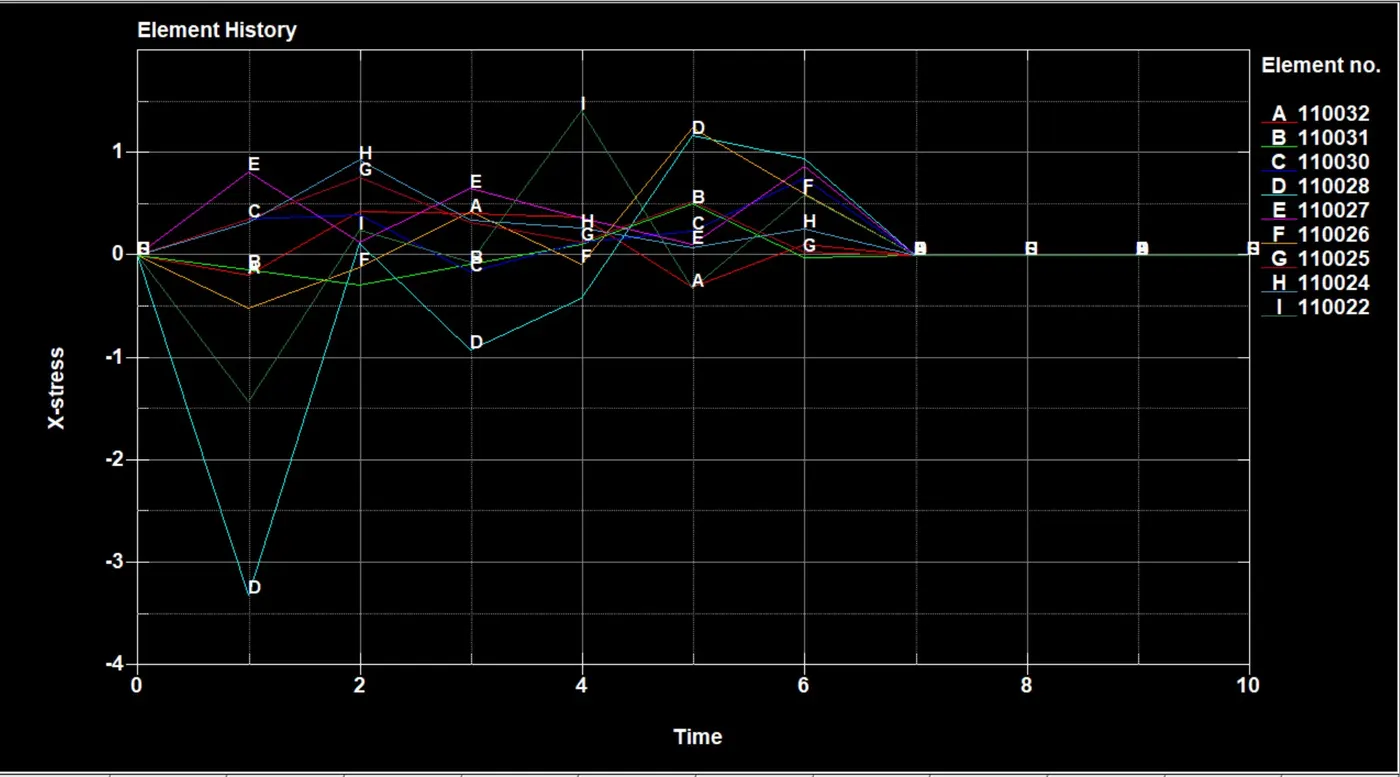
- Here, we can see maximum stress develop at 4ms is 2n/mm greenline and maximum compression at 1ms is -3.5n/mm at 7ms these brack .
Comparison:-
| Beam element | solid element |
|
|
| |
|
| |
|
| |
|
Conclusion:-
- In this challenge I learned the process to be followed to smooth the analysis procedure while working on a model.