Week - 5 - Modelling Spotwelds
Aim: Modelling Spotwelds using beam and solid elements by *MAT_SPOTWELD card.
Procedure:
1)Create the beam element between the parts. The beam elements are created by using the element generation command in the element and mesh section. In element generation option we have three options: beam, shell and solid, we will select the beam option. For proper understanding of the deck assign the PARTID, (PART ID:100). Now to create the beam, two nodes have to be selected, one from each component. THe similar procedure is used for creating solid elements as well, by opting solid option and two_Shell_Sets command. Below are the front view images of spotwelds using beam elements and solid elements.
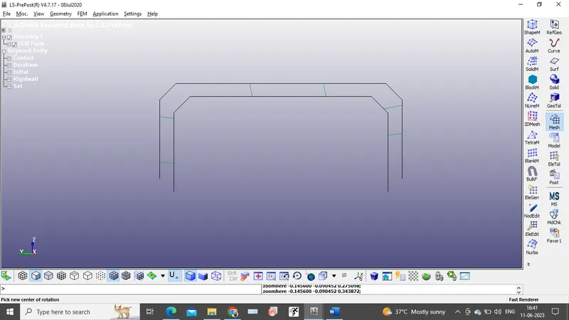
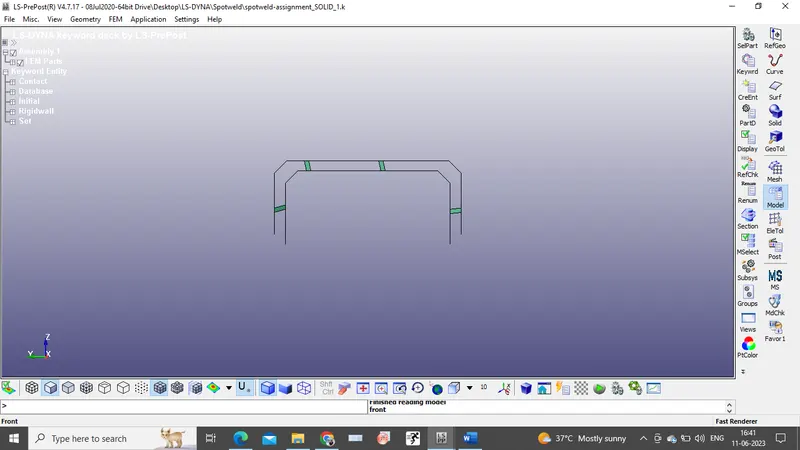
2)Go to keyword manager in the model and part group. In keyword manager we can observe the keywords assigned to the component. In the beginning of the solver deck only, element, node and part keyword will be present, we should add the keyword based on the requirements.
3)As we created a beam element, lets assign the section ID and material ID. Beam section is created with a ELFORM 9 w.r.t spotweld material and a thickness of 3mm and Shell Section ID is created for the parts with ELFORM 16. *MAT_SPOTWELD (100) and *MAT_ELASTIC (001) are created with the steel properties are assigned. (gm-mm-ms). Now assign the material IDs and Section IDs to all parts. Fof solid elements the suggested ELFOM is 1 for the *MAT_SPOTWELD(100).
4)Next step is to create the contacts between the spotweld beam nodes and the material to be spotwelded. Based on the *MAT_SPOTWELD Theory, *CONTACT_SPOTWELD is used. First, slave set ID and master set ID has to be created. (The stiffer part is selected as master part and the less stiffer part is slave. So, using the create entity option to create Part ID(MSID) and Node ID (SSID)are created respectively. *CONTACT_TIED_SURFACE_TO_SURFACE is reccommanded and also SSID and MSID has to be created.
5)For Crash simulation, rigid wall has to be created. A planar rigid wall is created at distance of 30mm from the Bottom part. Now create a node set ID so that velocity can be assigned. A velocity of 10mm/ms is assigned to the part.
6)Now *Control_Termination keyword is added to assign the end time i.e 10ms. *Database keyword is also specified with d3plot, ASCII(glstat, swforc, nodout), and history beam is also specified.
Conclusion:
1) A crash run is performed.
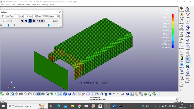
2)Axial and shear stresses in the solid elements.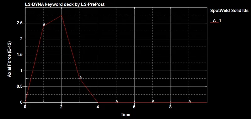
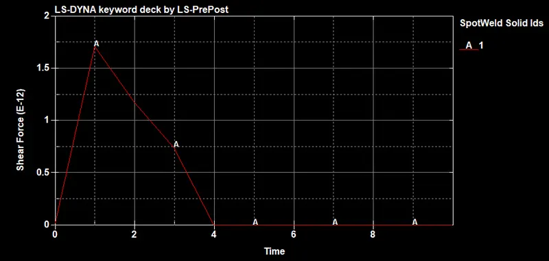
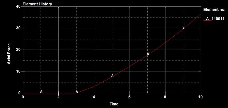
3)Axial force in beam elements.