Week - 5 - Modelling Spotwelds
AIM:
To model the spotweld for the given brackets with beam element and hexa_solid element and then compare the results bewteen them.
Given model:
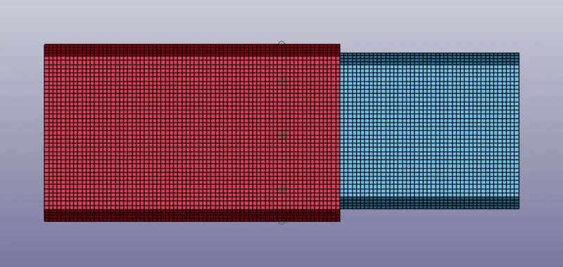
PROCEDURE:
Creating Beam element:
Go to mesh>element generation>beam>two node sets>select the two nodes click create and done. Symmetrically generate the beam elements between the two brackets.
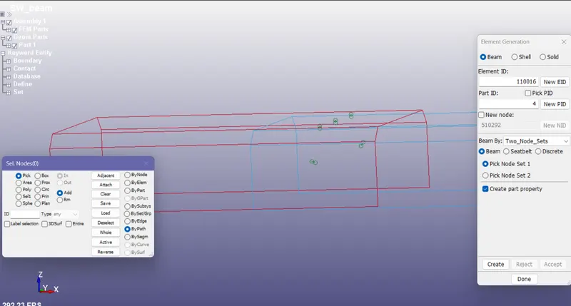
For creating hexa_solid element go to element tools>element edit>element type as hexa>select 8 nodes>click create>done.
Creating material cards:
spot weld:
For defining spot welds (100 - spotweld) card is used. The gm/mm/ms unit system is used so that the material properties are asssigned based on the selected unit system.
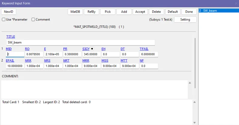
The spot weld failure time is given as 6ms and the corresponding axial and shear force quantities are determined. Next time the resultant axial and shear force values are entered in the material card and test the failure time.
Brackets:
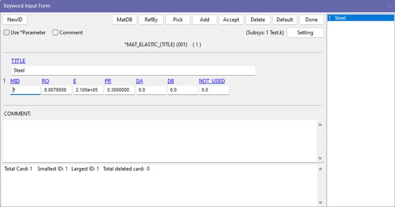
For brackets the elastic properties is assigned and steel properties are used.(001_Elastic)
Creating section:
Beam:
For beam, tubular cross section is selected with thickness 3mm through out the length of the beam. Element formulation 9 is selected to mention it as spot weld beam. Delete the automatically created section and pids.
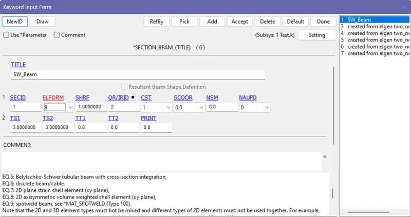
Shell section is used for brackets with element formulation of 16 more integration points to increase accuracy. 1.5mm thickness is assigned for the brackets.
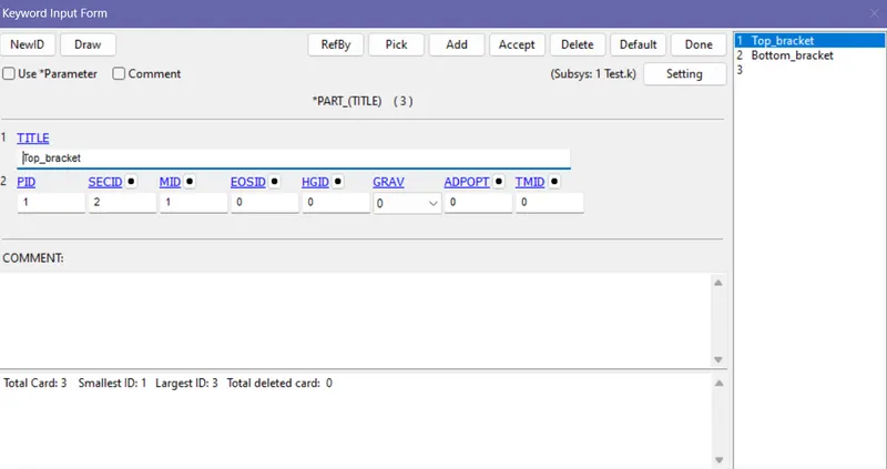
Now go to part assign the correcponding sections and materials for the particular pids.
Boundary Conditions:
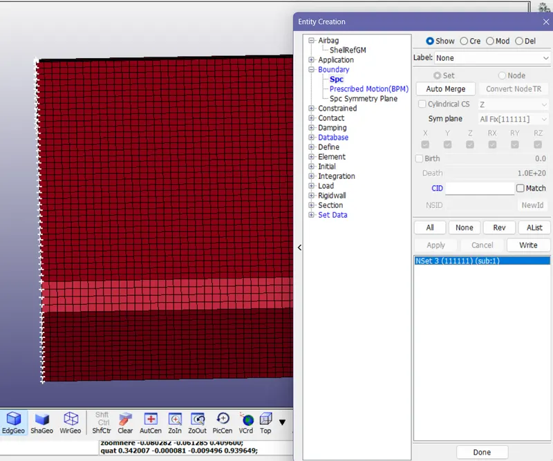
The instance used is one end is fixed and other end is applied with displacement. For creating fixed entities go to model>create entities>Boundary>spc>all fix(1,1,1,1,1,1). Use by area option and select all the nodes at one end. The node set will be automatically created.
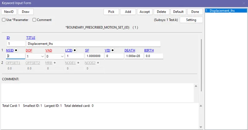
For applying displacement prescribed motion set is used. Before that the node set for brackets has to be created. For that go to set data>node set>Select all the nodes on the other end>accept>done.
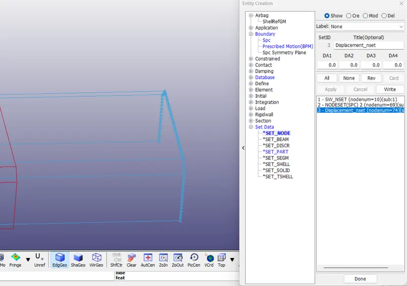
Now model>keyword>Boundary>prescribed motion set>select the node set> apply displacement in negative x displacement of 20mm by giving DOF as 1. Create a load curve to apply diaplacement gradually.
Contacts:
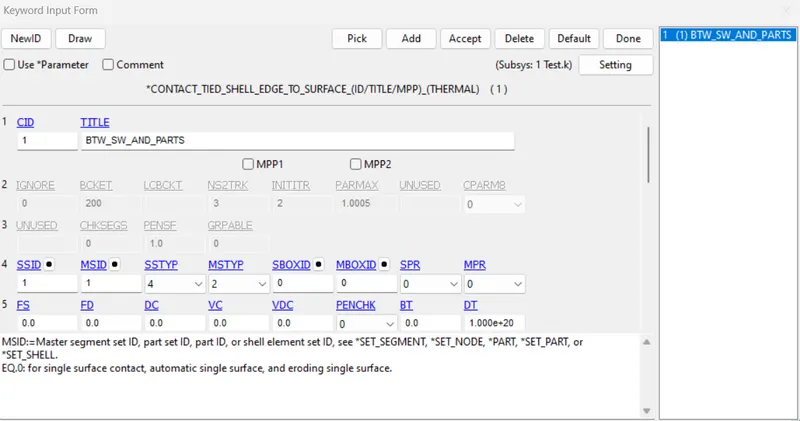
For difining contact between the spotweld and the brackets, Contact_Ties_shell_edge_to _surface is selected. Here the master set is the brackets and the slave sets are the spot weld elements. The spot elements are put into a separate node set to make the definition easier
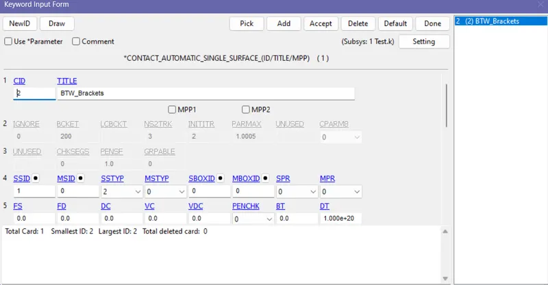
Once the spot weld get fails there will be a chance of top bracket penetrate over the bottom bracked for that a single surface contact is used to avoid penetration.
Control:
Termination:
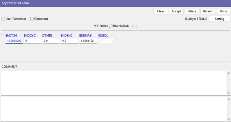
Give the end time for the simulation as 10 ms. At 10 ms a displacement of 20mm is applied and then failure time for spot weld is 6 ms.
Database:
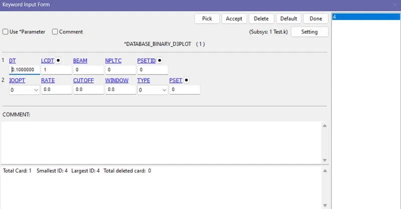
Binary d3_plot:
Give the time step as 0.1 so that the data are recorded for every 0.1ms.
History node:
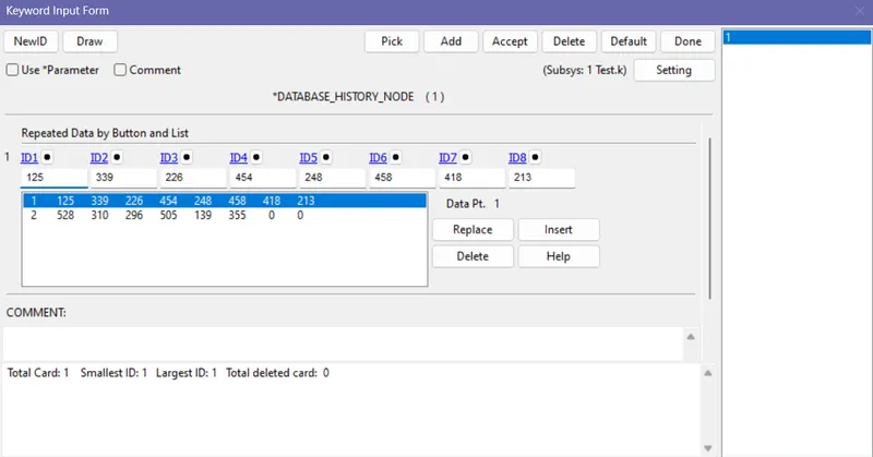
It is used to store information of nodes on the solution is done which can be used for nodeout results.
SWForce is used to see the spot weld results - resultant axial, shear, tortional momentum etc.
RESULTS:
Case1: BEAM ELEMENT
First the two brackets are constrained by spot welds. Then one bracket is fixed and other has displacement. Naturally one bracket tries to move away from other and the spot welds tries to resitrict the motion as it is a fixed joint.
Kinetic energy and internal energy in the brackets:
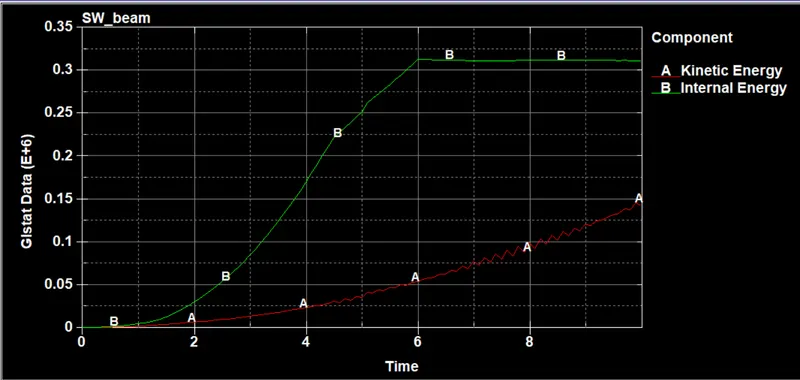
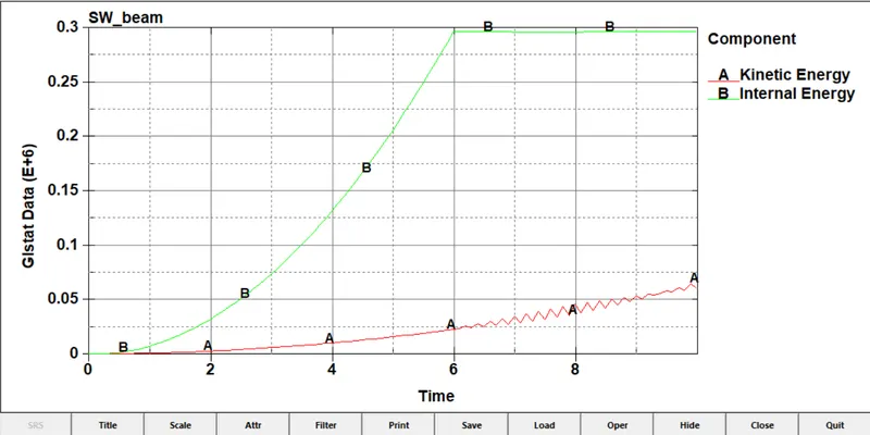
As the displacement is continuously applied, at one end kinetic energy is keeps on increasing. The failure time of the weld is 6 ms, up to 6ms the internal energy keeps on increasing and after that it becomes constant. Thats because the weld fails and it starts releasing the stored internal energy as kinetic energy that why the after 6ms kinetic energy increases rapidly.
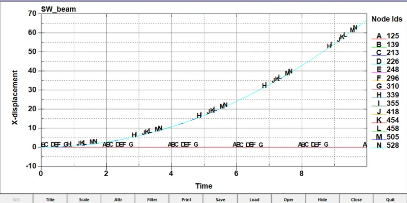
Nodal displacement;
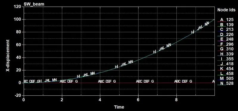
The nodes A,B,C,D,E,F,G are on the top bracket which is fixed so the displacement is zero throughout. The node H,J,K,L,M,N are on the bottom bracket which is displaced so that the stress is developed on the spot weld region.
AXIAL FORCE:
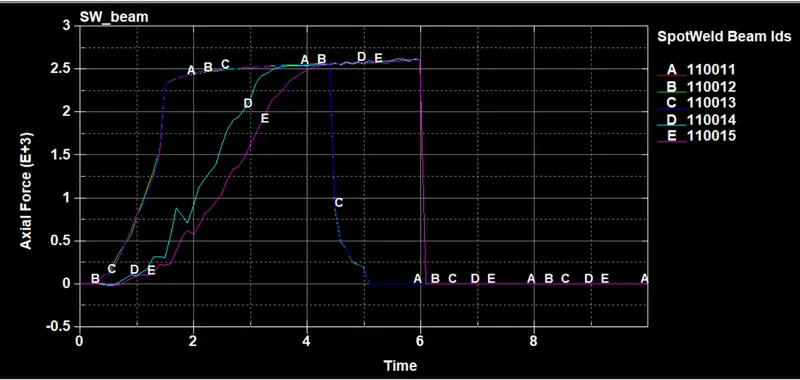
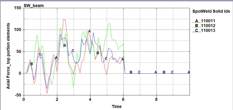
The maximum axial force it reaches is 2.6e+03 at 6ms. After 6ms the weld get break and the axial force suddenly drops to zero.
Shear force:
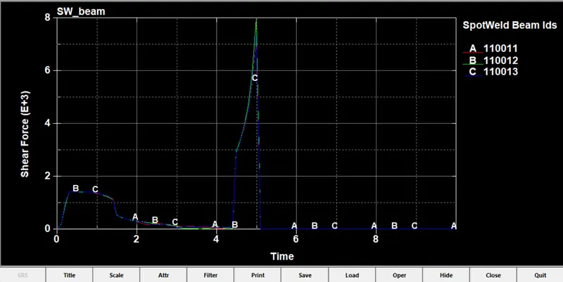
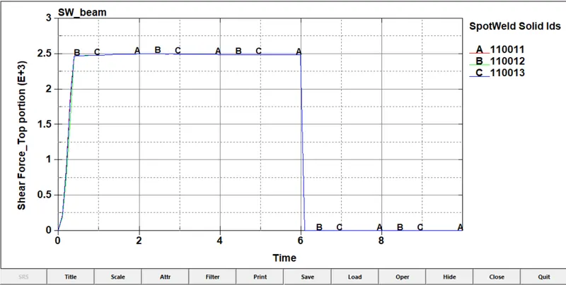
These three beam element are in the top portion and it has the maximum shear force of 8e+03.
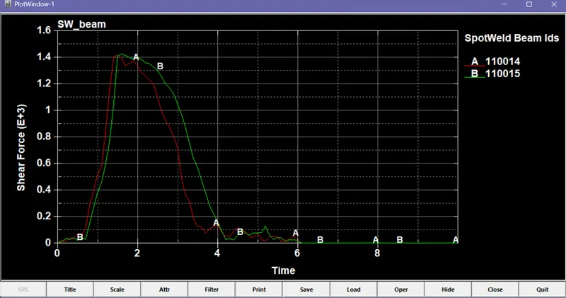
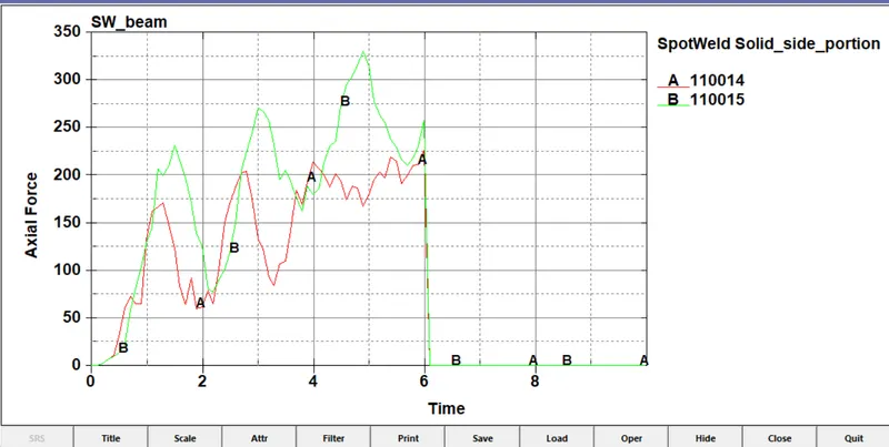
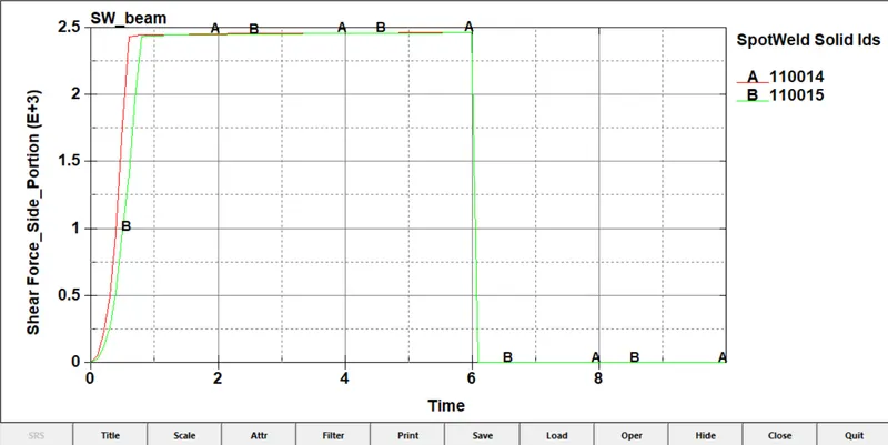
The beam element 110014, 110015 are the elements in the corner and the maximum shear force is 1.422+03.After 2ms the the shear force starts dropping because the elements in the corners are larger in length so it can't withstand larger shear force.
CASE 2 : HEXA ELEMENT:
The test case and conditions are similar to previous case and the beam element used is hexa solid element.
Stress acting on the brackets and beam elements:
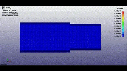
Kinetic energy and internal energy in the brackets:
Nodal displacement;
AXIAL FORCE:
Shear force:
RESULT:
From case 2 at 2.5e+03 amount of shear force the hexa beam element gets break which is similar to case 1 i.e.,beam element with tubular cross section with thickness of 3mm. All kinetic energy, internal energy and nodal displacement values are similar between the case 1 and case 2.