Week - 5 - Modelling Spotwelds
Aim: To simulate a crash test for sheet metal by modelling spot weld using Beam and solid (Hexa) elements using LS-Dyna.
OBJECTIVE:
- To create the material card.
- To create a section card for thickness 1.5 mm.
- To assign material and section card to the part.
- To define a rigid wall.
- To assign initial velocity to the crash box.
- To define spot welds using beam elements.
- To create a section card and material card to Beam element.
- To define a contact interface.
- To define control card.
- To define the output database as both binary D3 plot and ASCII.
- Model checkup and run the simulation.
- To define spot welds using solid (Hexa) elements.
- To assign section card and material card to solid Hexa element.
- To define a contact interface.
- To run the simulation.
PROCEDURE:
Open the LS-PrePost software, and then we have to import the required file i.e. spotweld-assignment, which is in .K format. So, in order to import the .K file format model in LS-PrePost, we have to follow:
File--->Import---->LS-DYNA Keyword File---->File: select file--->Import.
Once model is opened, it will look like as shown picture in below.
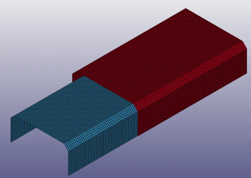
In order to check the keywords contained in the file we have to follow:
Model and Part---->Keyword Manager---->check: Model
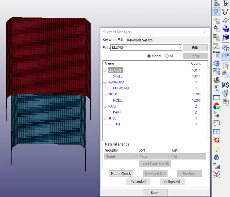
From above we can notice, we have shell element present in the model. Also according to analysis point of view, we need only shell element. Also we have not find any material and section card defined in the model.
Before creating these cards, first we will check duplicates of element. If find, we will remove them first then proceeds further.
To check duplicate elements:
In order to check duplicate elements. First we have to check duplicated node by following:
Element Tools---->Duplicate Nodes---->Select node: by area---->Show Dup Nodes.
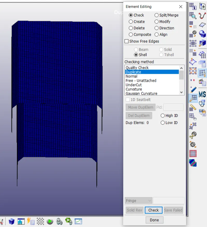
If duplicate nodes are found then we have to merge these nodes because one, two or three elements belong to same node. So, 0 duplicate nodes are found as shown in above picture. Also, we can say model is cleaned.
1. To create the material card.
Now we have to assign material card for spotweld_assignment model. In order to assign material we have to follow steps shown below
Model and Part---->Keyword Manager---->All---->MAT.
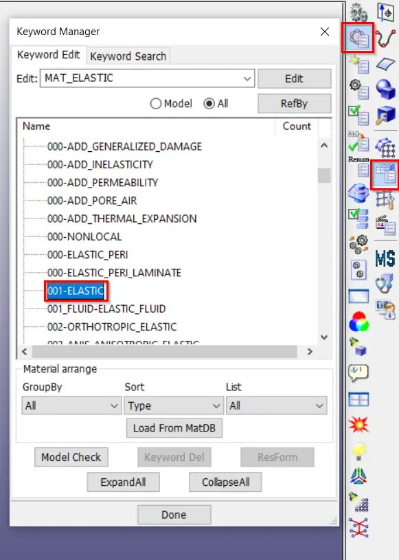
For spotweld_assignment we have to assign MAT_ELASTIC. This is Material Type 1. This is an isotropic hypoelastic material and is available for beam, shell, and solid elements in LS-DYNA. In order to assign material we have to follow
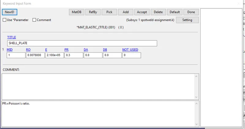
Where,
MID: Material identification.
RO: Mass density
E: Young’s modulus
PR: Poisson’s ratio
2. To create a section card for thickness 1.5 mm
In this section, the element formulation, integration rule, nodal thicknesses, and cross-sectional properties are defined. All section identifiers (SECIDs) defined in this section must be unique, i.e., if a number is used as a section ID for a beam element then this number cannot be used again as a section ID for a solid element. The keyword cards in this section are defined in alphabetical order. Now, we are having solid elements, so we will use section solid.
In order to create section solid we have to follow steps as shown:
Model and Part---->Keyword Manager---->All---->SECTION.
First we will create section shell for crash box as shown in picture below with thickness 1.5 mm.
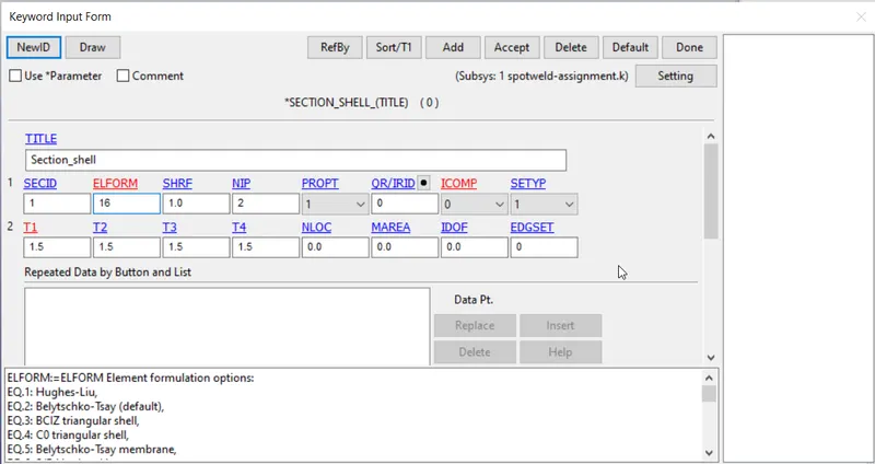
Where, SECID is Section ID.
ELFORM is Element formulation.
SHRF is Shear correction factor which scales the transverse shear stress.
NIP is Number of through thickness integration points.
3. To assign material and section card to the part.
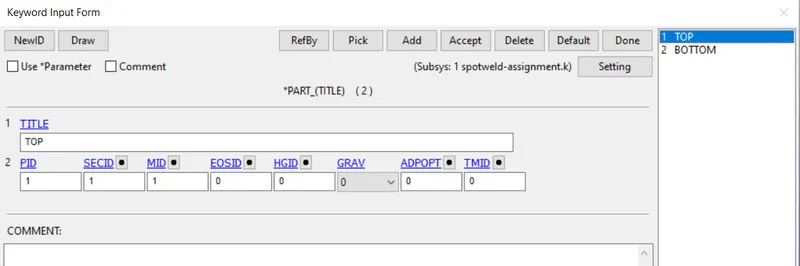
Once material and section card is created for each part of spotweld_assignment model. Now we have to assign both cards to their respective parts as shown in picture below.
4. To define a rigid wall.
The RIGIDWALL provides a easy way to define a contact between a rigid surface and nodal points of a deformable body, called slave nodes. A rigid wall is defined by a surface type and a group of slave nodes. Each wall can be fixed or moving. A rigid wall is a kinematic condition.
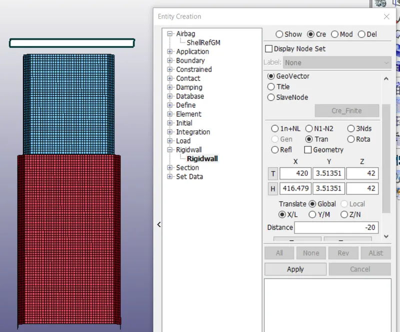
So a rigid wall is created ahead of spotweld_assignment model. So that spotweld_assignment model should crash into a rigid wall created. And rigid wall should create at some distance from spotweld_assignment model, because spotweld_assignment model have to move with some initial velocity. Also, we have to take care about rigid wall normal vector direction. It should be facing crash box. In order to create rigid wall we have to follow.
Model and Part---->Create Entity---->Rigidwall.
5. To assign initial velocity to the crash box.
Define initial nodal point velocities using nodal set ID’s. This may also be used for sets in which some nodes have other velocities.
In order to assign initial velocity, first we have to create node set id for crash. In order to create node set id we have to follow:
Model and Part---->Create Entity---->Set Data---->Set Node.
Once node set ID is created for crash it will look like as shown in picture below.
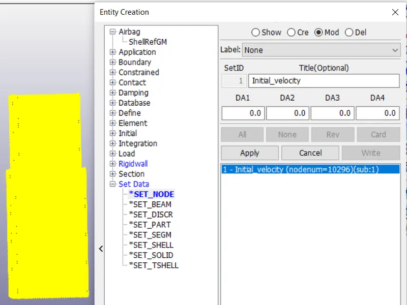
Now we have create initial velocity to selected set nodes of crash box as shown in picture below.
Model and Part---->Keyword Manager---->INITIAL---->VELOCITY.
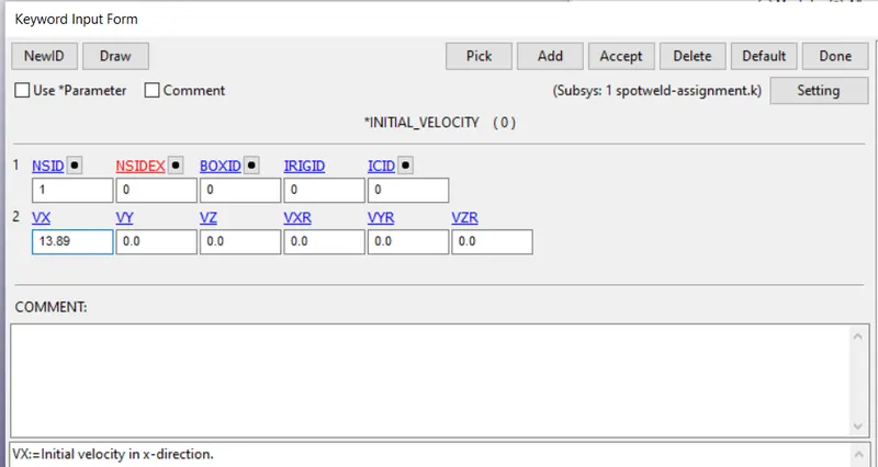
6. To define spot welds using beam elements.
Spot welding is also know as resistance spot welding is a type of electric resistance welding used to weld various sheet metal products, through a process in which contacting metal surface points are joined by the heat obtained from resistance to electric current.
The process uses two shaped copper alloy electrodes to concentrate welding current into a small "spot" and to simultaneously clamp the sheets together. Work-pieces are held together under pressure exerted by electrodes. Typically the sheets are in the 0.5 to 3 mm (0.020 to 0.118 in) thickness range.
The spot weld is a rigid beam that connects the nodal points of the nodal pairs; thus, nodal rotations and displacements are coupled. The spot welds must be connected to nodes having rotary inertias, that is, beams or shells. If this is not the case, for example, if the nodes belong to solid elements, use the option: *CONSTRAINED_RIVET. During implicit calculations this case is treated like a rivet, constraining only the displacements. Note that shell elements do not have rotary stiffness in the normal direction and, therefore, this component cannot be transmitted.
To create a spot weld using Beam elements we have to follow:
Element and Mesh---->Element Generation---->Beam.
Also we need to create 3-7 spotwelds along this line, in a symmetric manner.
Now we have to pick two nodes and then have to click on accept as shown in picture below.
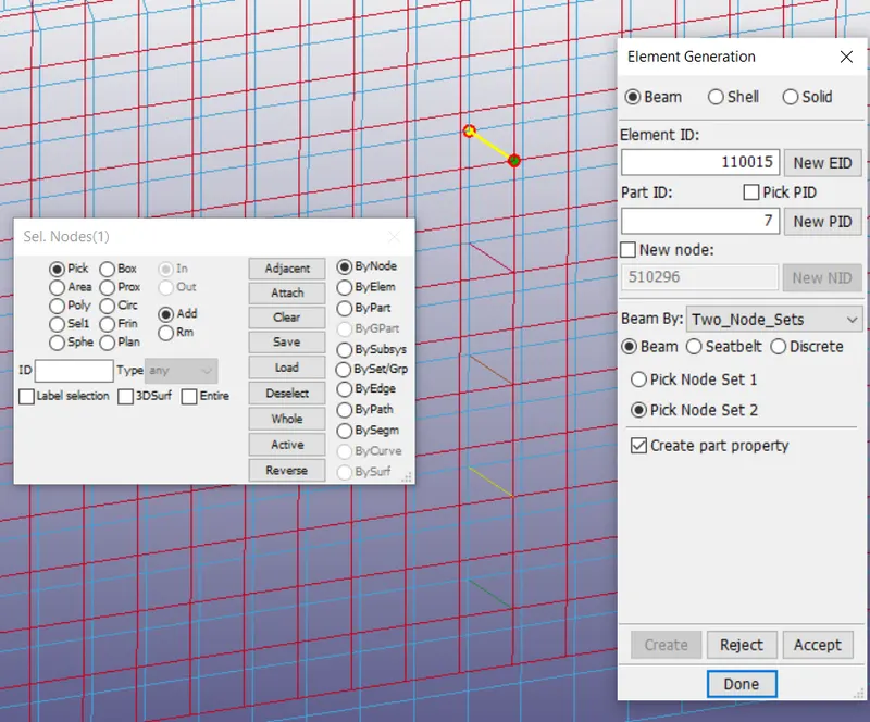
7. To assign section card and material card to Beam element.
7.1. To create a section card
Section_Beam is section card for Beam element as shown in picture below.
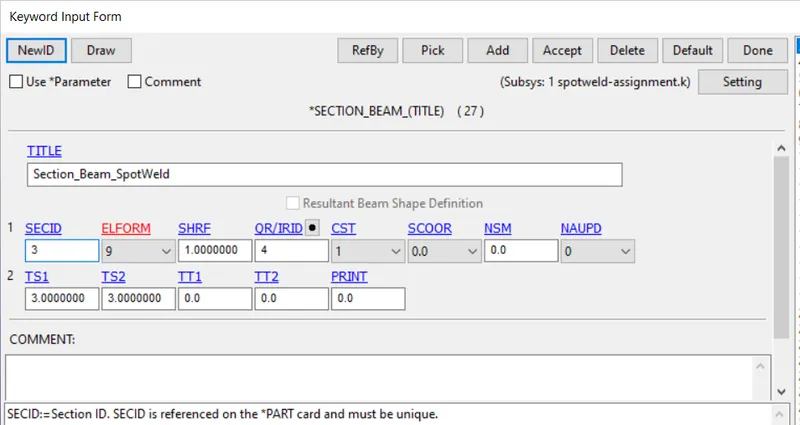
7.2. To create a material card
MAT_SPOTWELD is material card for spot weld beam elements as shown in picture below.
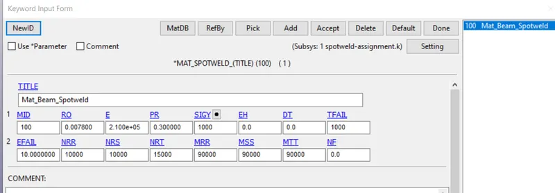
7.3. To assign section card and material card to Beam element
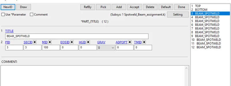
8. To define a contact interface.
The keyword *CONTACT provides a way of treating interaction between disjoint parts. Now we have to define contact interface. Before defining contact card, first we have to create set data segment, in which we will create segment for spotweld_assignment model and connecting nodes of beam elements (in which we will select those elements or nodes which are going to interact during simulation).
First we will define a set of nodes with GENERATE_INCREMENT options will generate block(s) of node IDs between a starting ID and an ending ID. An arbitrary number of blocks can be specified to define
the node set.
In order to create set of segments we have to follow:
Model and Part---->Create Entity---->Set Data---->SET_NODE.
Once segments are created, it will look like as shown in picture below.
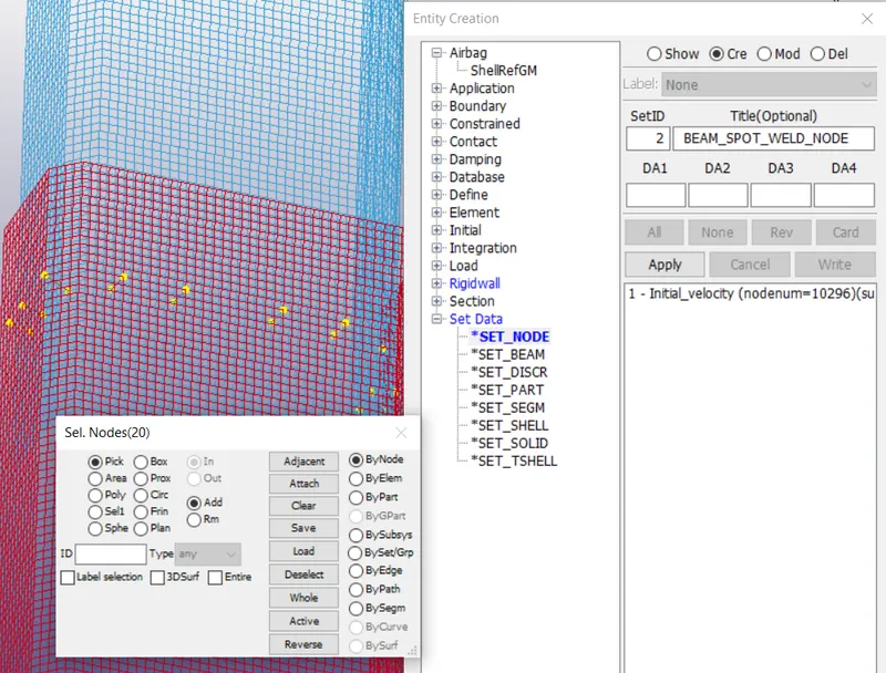
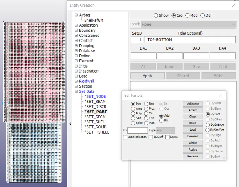
Now we will create Set_Data using SET_PART, where we will select all elements for Top and bottom plates of shell elements for spotweld_assignment model. Once SET_PART card is generated, it will look like as shown in picture below.
8.1. TIED_SHELL_EDGE_TO_SURFACE
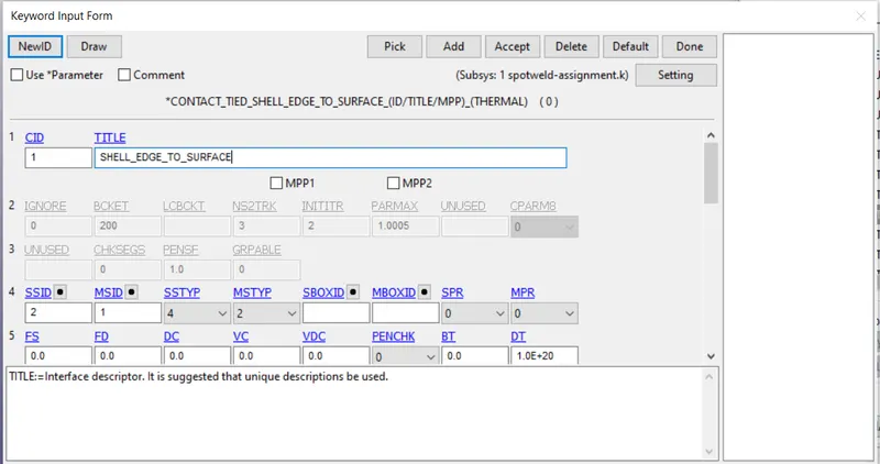
In order to create contact card, we have to select contact Tied_Shell_Edge_To_Surface for spotweld_assignment model. In which slave segment type is node set ID for node to surface contact, which includes nodes which connects either end of beam elements. And in master segment type we will select part set ID, which includes top and bottom shell elements parts.
For tying shells-to-shells, beams-to-shells, that is, for situations where all the nodes have rotational degrees-of-freedom, use TIED_SHELL_EDGE_TO_SURFACE type contacts. This contact type may include the OFFSET, CONSTRAINED_OFFSET, or BEAM_OFFSET option. In order to create contact card we have to follow:
Model and Part---->Keyword Manager---->CONTACT.
Once card is created and all parameters are assigned, contact card will look like as shown in picture below.
8.2. AUTOMATIC_SINGLE_SURFACE
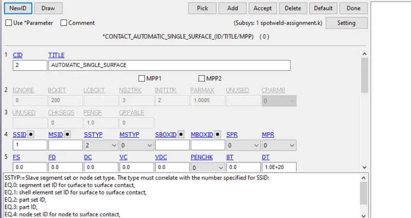
In order to create contact card, we have to select contact automatic single surface for spotweld_assignment model. In which slave is top and bottom shell plates.
This special feature was originally implemented to allow for the calculation of eigenvalues and eigenvectors on geometries that are connected by a contact interface using the automatic single surface options. It also can be used in a more general sense to tie a set of parts based only on their proximity to each other in the initial geometry.
In order to create contact card we have to follow same steps as explained for above case.
Once card is created and all parameters are assigned, contact card will look like as shown in picture below.
9. To define control card.
We use the reduced integration point formulation method which introduce the hourglass energy in the simulation. To reduce hourglass energy, it is necessary to enable the hourglass card in the energy card from keyword card and enable hourglass card from control keyword.
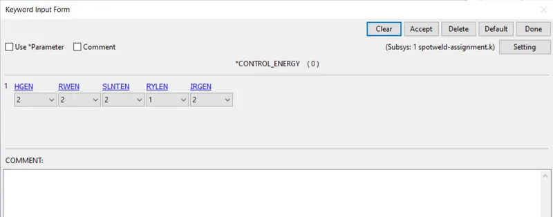
9.1 The purpose of creating control energy card, provide controls for energy dissipation options. In order to assign control energy card we have to follow:
Model and Part---->Keyword Manager---->CONTROL---->ENERGY.
Once control energy card is set, card will look like as shown in picture below
Where,
HGEN Hourglass energy calculation option.
RWEN Rigidwall energy dissipation.
SLNTEN Sliding interface energy dissipation option
RYLEN Rayleigh energy dissipation option (damping energy dissipation):
IRGEN Initial reference geometry energy option.
9.2 The main purpose of control termination card is to stop the job. In order to assign control termination card we have to follow:
Model and Part---->Keyword Manager---->CONTROL---->TERMINATION.
Once control termination card is set, model will look like as shown in picture below.
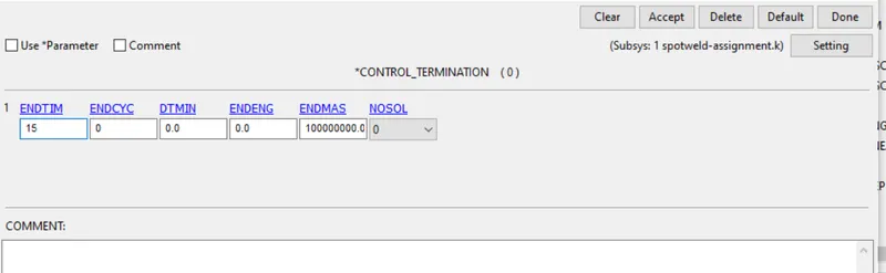
ENDTIM: Termination time. Mandatory.
ENDMAS: Percent change in the total mass for termination of calculation.
This option is relevant if and only if mass scaling is used to limit the minimum time step size.
10. To define the output database as both binary D3 plot and ASCII.
The database definitions are optional, but they are necessary to obtain output files containing results information. The ordering of the database definition cards in the input file is completely arbitrary. The purpose of database binary is to request binary output file.
DATABASE_BINARY_D3PLOT ensures d3plot files in which it stores stress strain contours of the entire deformed model. In order to create DATABASE_BINARY_D3PLOT we have to follow:
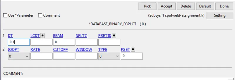
Where, DT defines the time interval between output states.
DATABASE_HISTORY_NODE Control which nodes or elements are output into the binary history file
d3thdt, the ASCII file nodout, the ASCII file elout and the ASCII file sphout. In order to create DATABASE_HISTORY_NODE we have to follow:
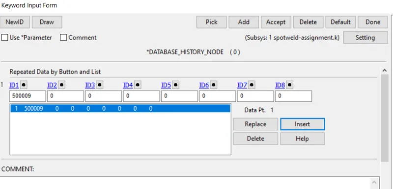
ASCII can generate different outputs such as force generated in a contact like total energy, material energy etc. In which we will request GLSTAT, MATSUM, NODOUT, RCFORC, RWFORC, SECFORC, SLEOUT are been requested as shown in picture below.
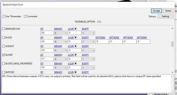
GLSTAT is global statistics and energies.
MATSUM is material energies.
NODOUT is Nodal displacement/velocity/acceleration data
RCFORC is resultant interface force.
RWFORC is RigidWall forces.
SECFORC is cross section force data.
SLEOUT is sliding interface energies.
11. Model checkup and run the simulation.
Now model will be check for errors, if found it needs to correct. Warnings we can ignore. Once model check is run, it will look like as shown in picture below.
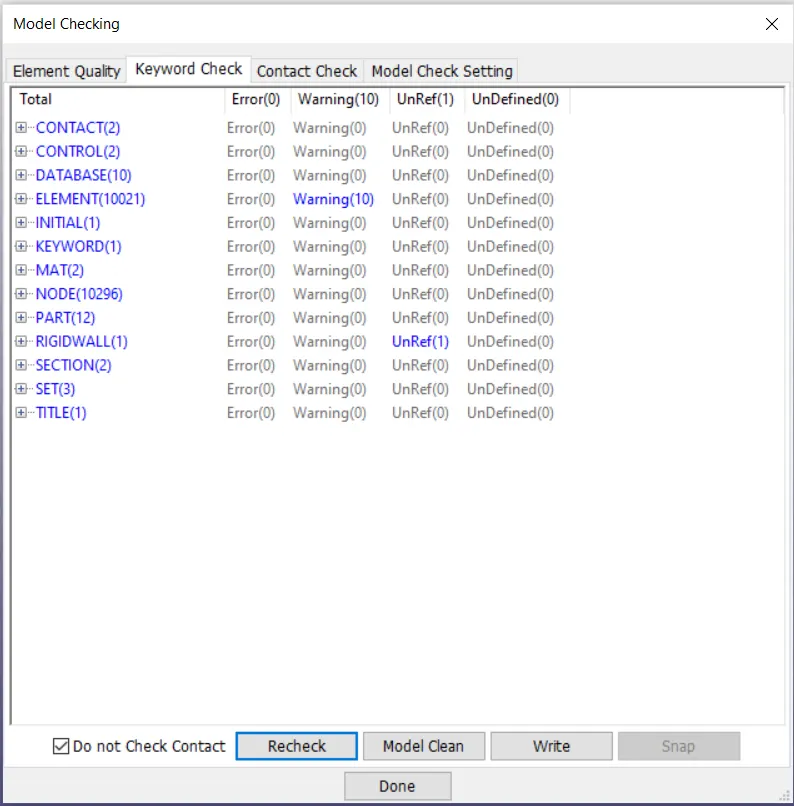
To run simulation:
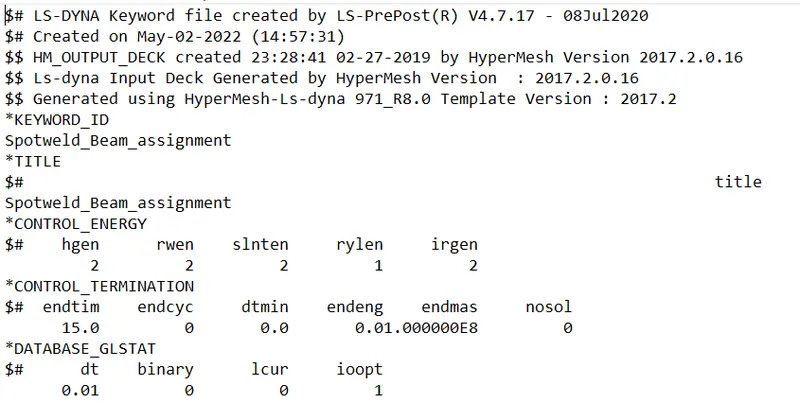
Before running simulation we have to edit the K file and have to edit the KEYWORD ID, so that after simulation all files should be generated with proper format as shown.
Now we have to run simulation, in order to run simulation we have to use LS-Run. Once LS-Run is opened, then we have to assign all required parameters then simulation will process as shown in picture below.
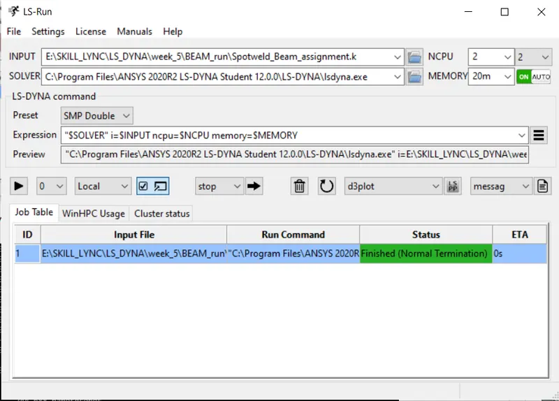
During simulation run window will pop up.
If normal termination occurs after running, it means the model is ready for post-processing.
In order to see simulation results, we have to open output file .d3plot file in LS-PrePost.
Contour plot for Von Misses stress
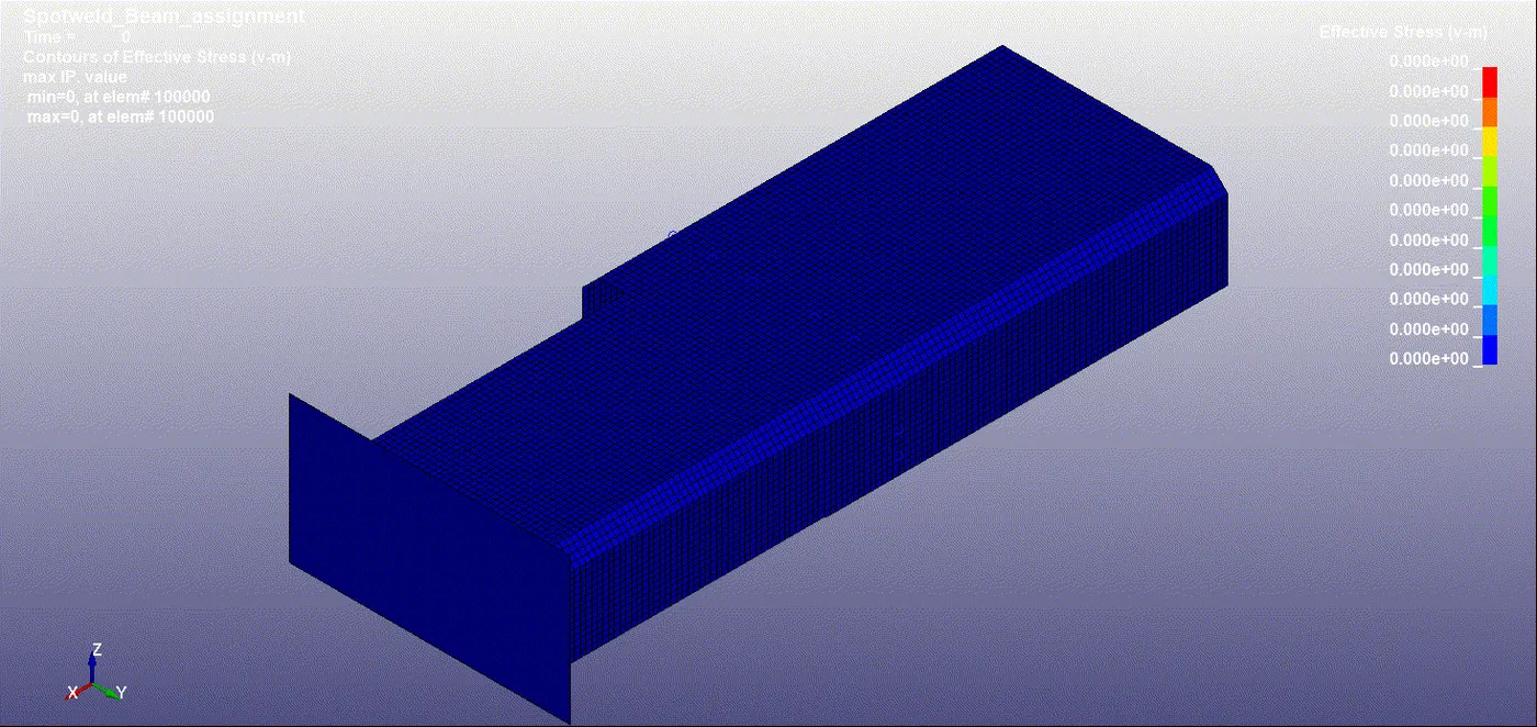
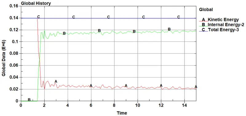
ENERGY PLOT for Beam spot weld:
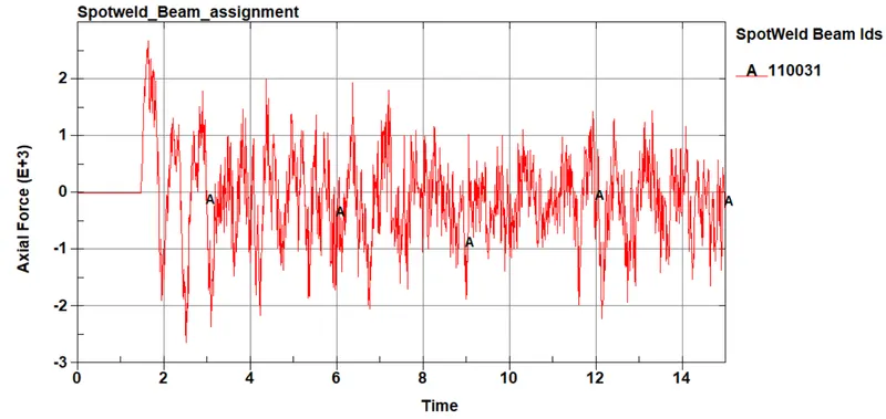
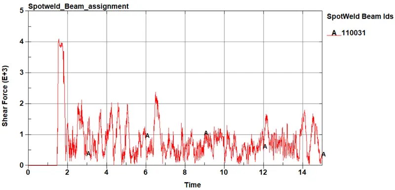
Forces generated for Beam spot weld:
12. To define spot welds using solid (Hexa) elements.
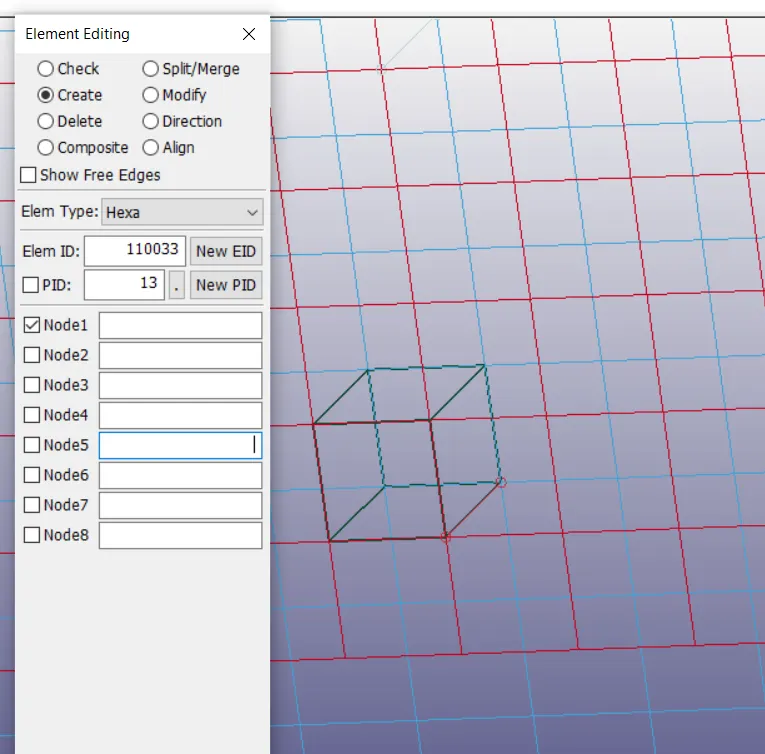
To create a spot weld using Solid elements we have to follow:
Element and Mesh---->Element Editing---->Hexa.
Also we need to create 3-7 spotwelds along this line, in a symmetric manner.
Now we have to pick four nodes from each shell element plates and then have to click on accept as shown in picture below.
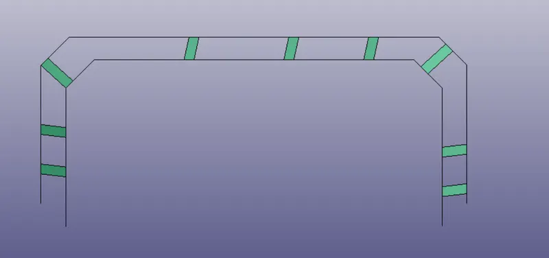
Once all spot-welds are created using Hexa elements, model will look like as shown in picture below.
13 To assign section card and material card to solid Hexa element.
13.1. To create a section card
Section_Solid is section card for Solid Hexa element as shown in picture below.
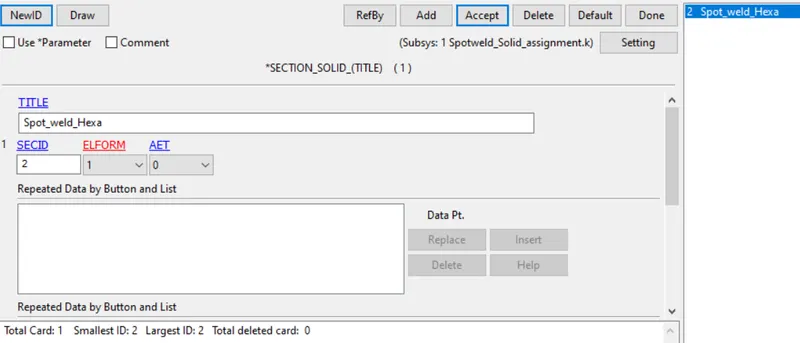
We can use the existing material card to solid Hexa elements. And then we will assign existing material card and new section card to spot weld hexa elements.
14 To define a contact interface.
CONTACT_SPOTWELD
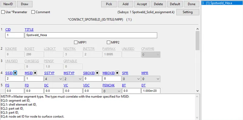
15 To run simulation:
Before running simulation we have to edit the K file and have to edit the KEYWORD ID, so that after simulation all files should be generated with proper format as shown.
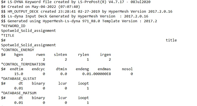
Now we have to run simulation, in order to run simulation we have to use LS-Run. Once LS-Run is opened, then we have to assign all required parameters then simulation will process as shown in picture below.
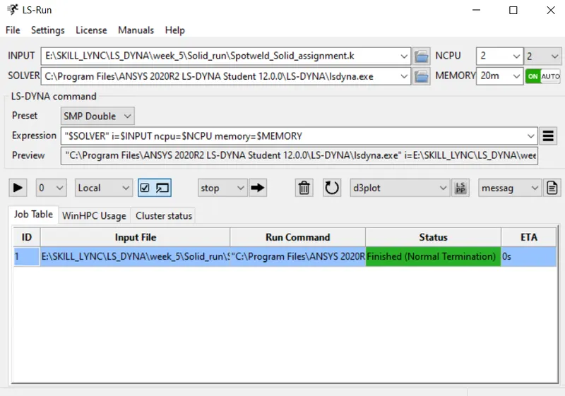
During simulation run window will pop up.
If normal termination occurs after running, it means the model is ready for post-processing.
In order to see simulation results, we have to open output file .d3plot file in LS-PrePost.
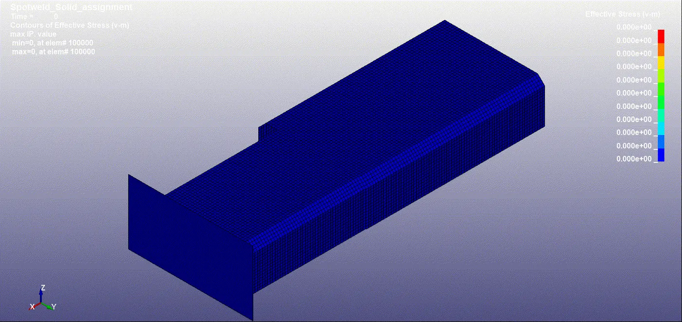
Contour plot for Von Misses stress:
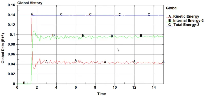
ENERGY PLOT for Hexa solid spot weld:
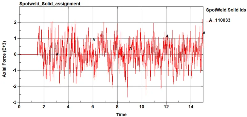
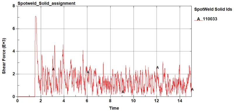
Forces generated for Hexa solid spot weld:
Learning Outcomes
I. The spot welds are modelled successfully using Beam and solid elements for the same sheet metal components.
II. The cards and other keywords are assigned successfully for spot-welds and plates.
III. Simulation has been done successfully.
IV. All the output requests have been calculated.