Week - 5 - Modelling Spotwelds
- Aim :- To model spotwelds for the given assembly of parts and run a crash test using beam and hex weld element for the spotweld.
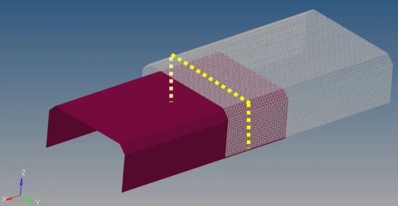
Details about spotweld location is in the image below. The yellow line signifies the spotweld directions. Using 3-7 spotwelds along this line, in a symmetric manner, connect the parts and run the simulation.
 \
\
- Procedure:
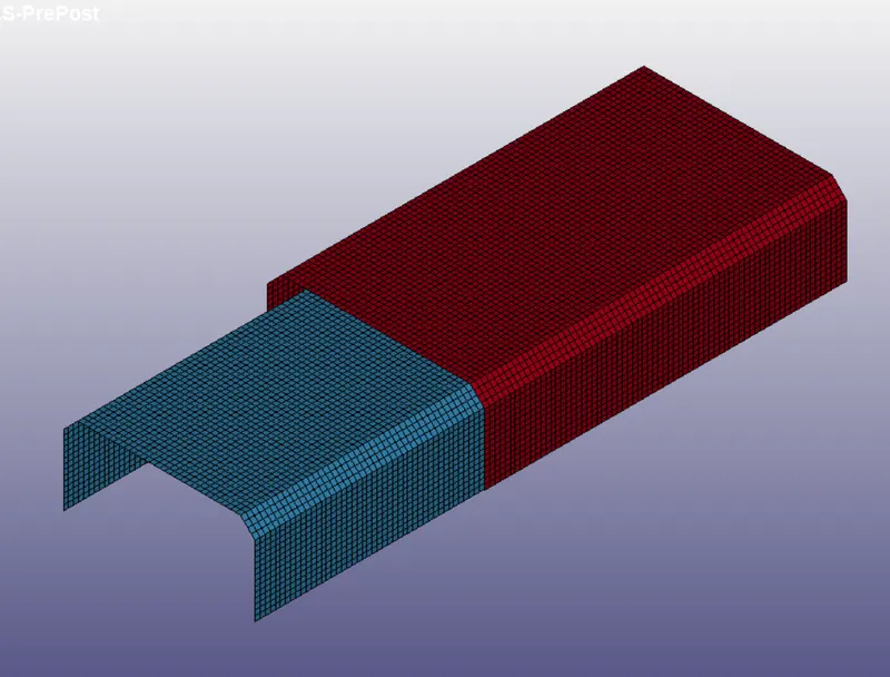
Open the .k file. The model is as shown below. There is no connection between the top shell and the bottom shell as seen below.
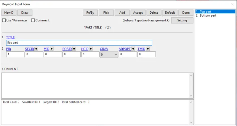
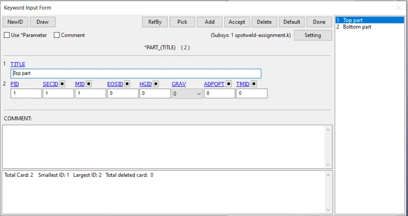
Also, in the keyword manager, it is seen that there is no material and section id defined in the Part keyword.
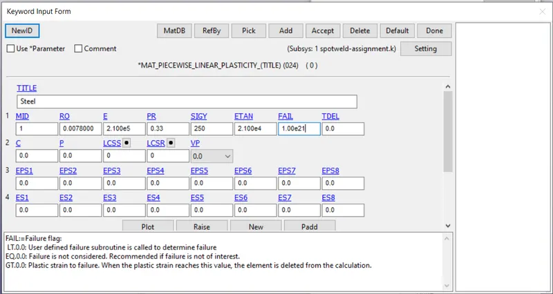
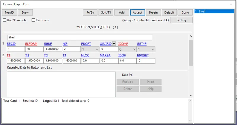
The material properties of steel is used for the top and bottom shell. Material model used is MAT24, i.e Piecewise_Linear_Plasticity, which models an Elastic-Plastic material. Section_shell is created as shown in the figure below. The thickness of the shell element and the element formulation for fully integrated element is defined using Section_shell.
The material id and the section id are updated in the Part keyword for the top shell and the bottom shell.
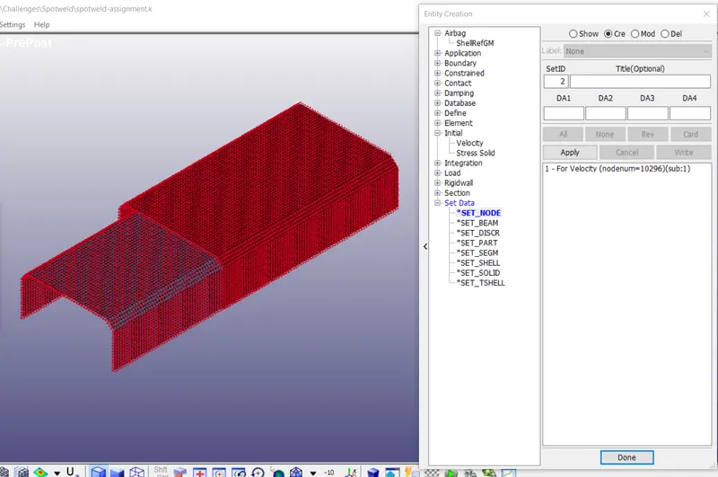
The crash box is supposed to hit the rigid wall with an initial velocity of 13.88 mm/ms. A node set needs to be created, so that the initial velocity can be applied to that node set directly. To create node set, go to Entity Creation > Set Data > Set_Node > Create. Select the active nodes and create a node set.
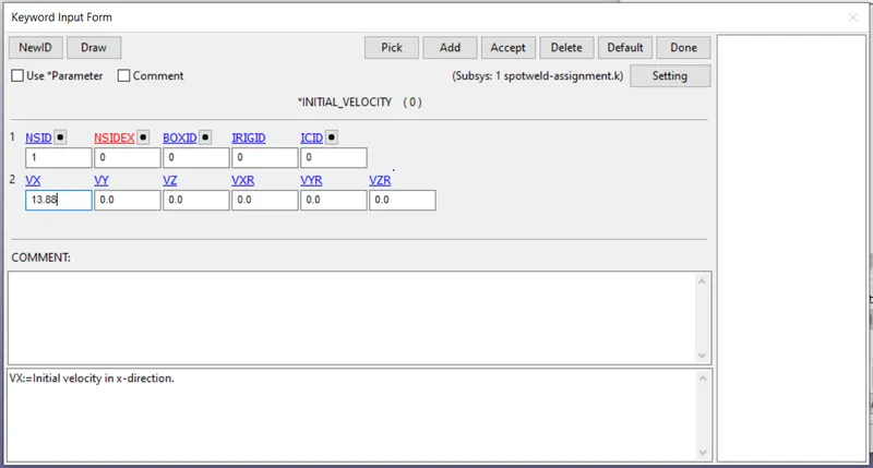
Using Initial_Velocity Keyword, apply the velocity in X direction for the created node set as shown below.
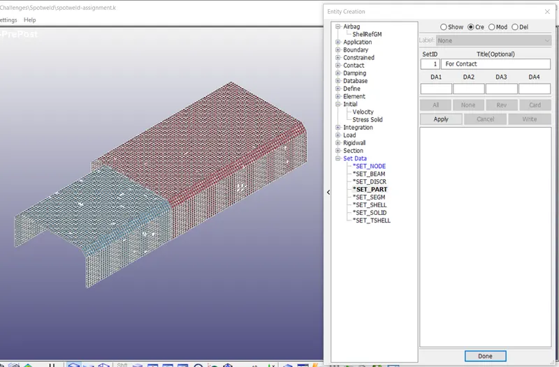
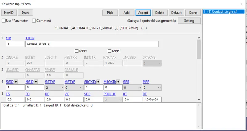
After impact, it may be possible that the crash box comes in self contact because of crushing action. Also if the weld elements fail, the top and bottom shell may come in self contact. To avoid any penetration in this case, contact between the top and bottom shell is created using Contact_Automatic_Single_surface keyword. A part set containing both the top and bottom shell is created first as shown below. This part set is used to define the slave set part id for Contact_Automatic_Single_surface.
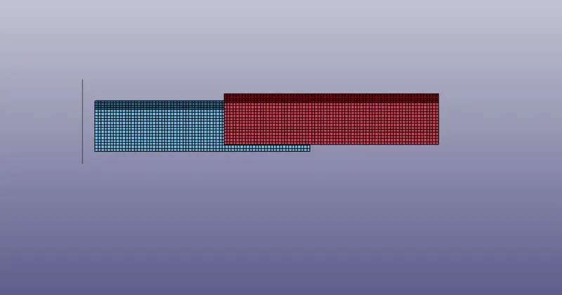
Now create a planar rigid wall so that the crash box can hit the wall. Go to Create Entity > Rigid Wall > Create to create a rigid wall. The planar rigid wall is positioned as shown below.
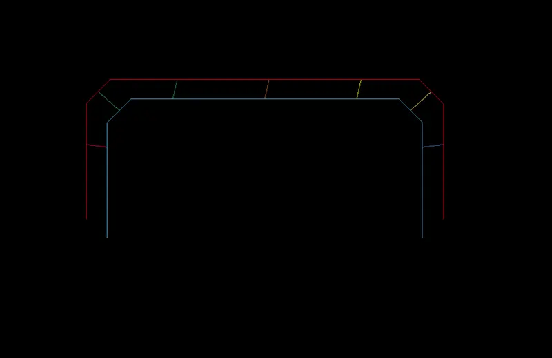
Now create beam element representing the weld elements. Go to Element and Mesh > Element Creation > Beam. Pick the nodes between two parts and create the spotwelds as shown below.
The properties for the weld element needs to be defined. Using Mat100 keyword, create a new material model for the weld element. Properties of steel is used for the weld element. Time based failure for the spot element is to be defined, therefore the other parameters are set to a high value as shown below.
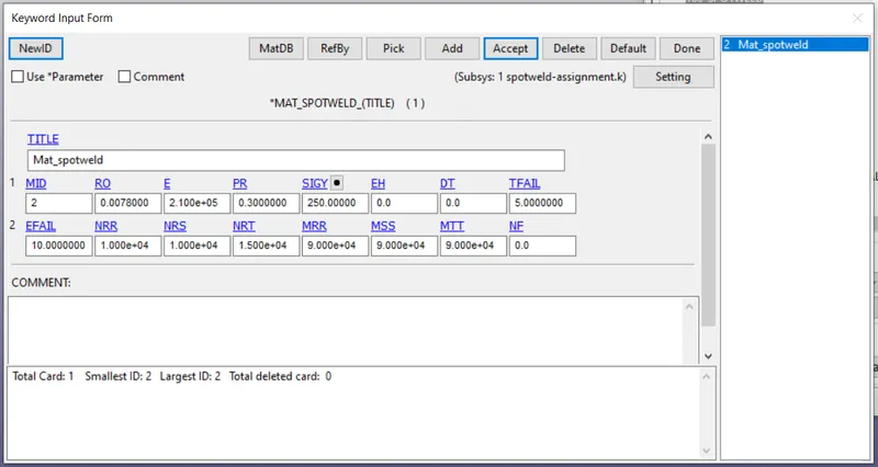
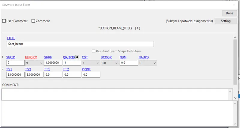
After creating material model for the spolt weld, we need to define section id for the beam element. Same is created using Section_Beam keyowrd. Element formulation 9 (spotweld beam)is used as MAT100 applies to beam element type 9.
Update the material id and the section id for the spotweld. Using Control_Termination card, end time of 10 ms is defined. All the needed input for running the simulation are submitted. Also tied_shell_edge_to_s/f contact is defined between the weld element and the top and the bottom shells with weld element as slave and the shell parts as master. Request the desired output using ASCII options and Binary_D3plot.
The following output data is requested using the *DATABASE card for writing the output data.
DATABASE_BINARY_D3PLOT
DATABASE_ASCII_GLSTAT
DATABASE_ASCII_RCFORC
DATABASE_ASCII_SLEOUT
DATABASE_ASCII_SECFORC
DATABASE_ASCII_SWFORC
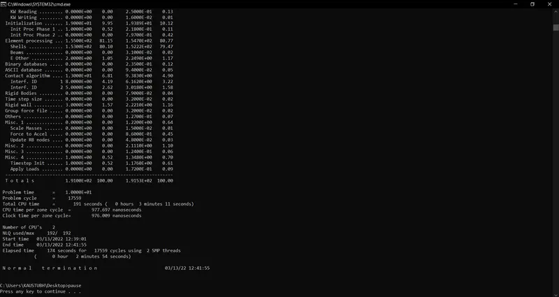
Save the keyword file and run the simulation. Before running the silumation, no errors are observed using the model check. Run the simulation. Processing is completed with normal
termination as observed.
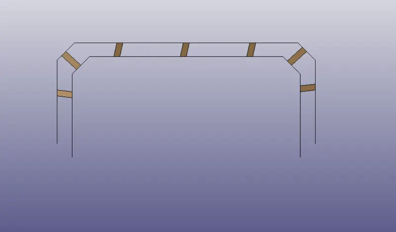
Similarly, we can create hex element for the spotweld and connect the top and bottom shell as shown below. The same mtl properties are used for the weld element. The only difference being that section solid is used with Element formulation = 1 as Mat100 applies to solid element with Element formulation =1.
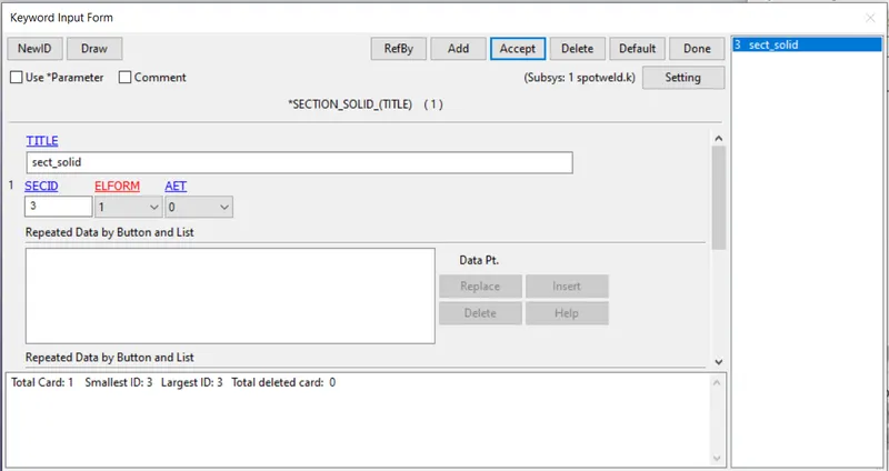
Also the contact between the weld elements and the shell elements is defined using Contact_Spotweld keyword. When creating any set for any master entity type, single set containing both the master shells is created, so that any instability in contacts are avoided.
Results:
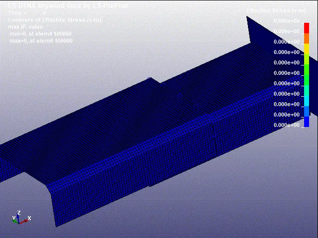
Von-Mises stress contour for beam weld element
Von-Mises stress contour for solid weld element
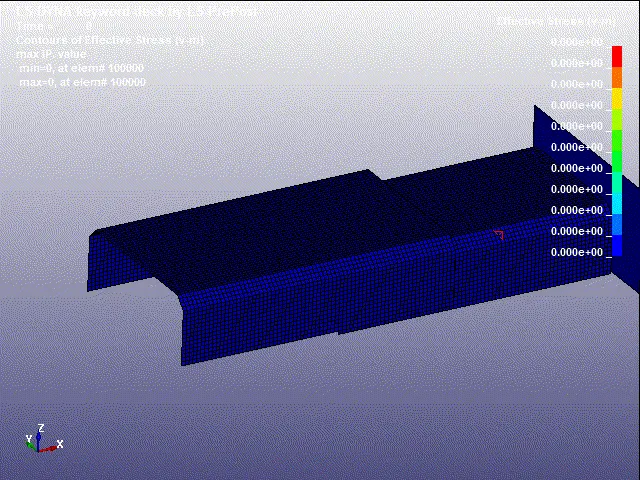
The stress contour in the model for both cases can be seen above. Max stress location is same (at the proximity of weld elements) in both cases, but they differ in magnitude. Max stress is observed in the model with beam weld element.
Effective plastic strain contour:
- Beam element:
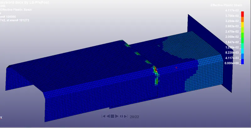
- Solid Element:
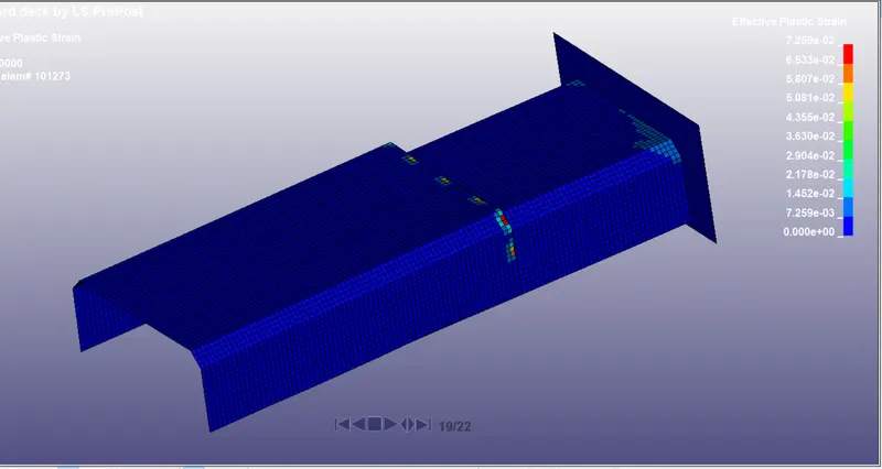
It can be observed that the strain in case of model with hex weld element is comparitively higher compared to model with beam weld element.
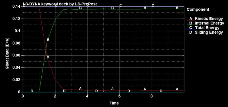
Energy Plot:
- Beam element
- Solid Element
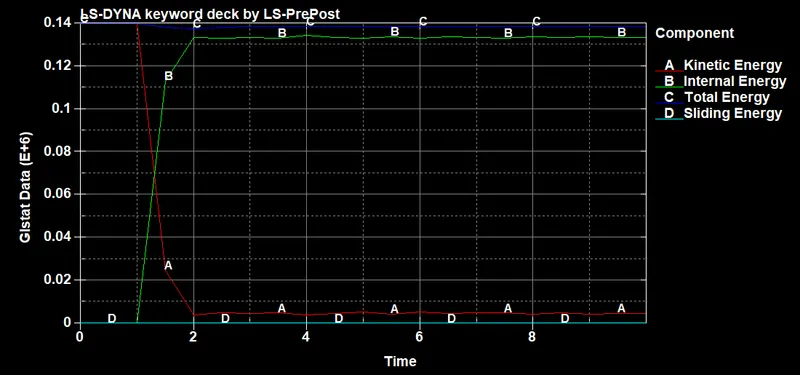
In both the cases, the kinetic energy is constant and internal engery is zero before impact. As the impact happens the kinetic energy lost is converted into internal energy due to deformation. The total energy remains almost constant in both the cases as kinetic energy lost due to impact is converted into internal energy and the sliding energy observed is also zero. Hourglass energy will also be zero, since element formulation for full integration points is used.
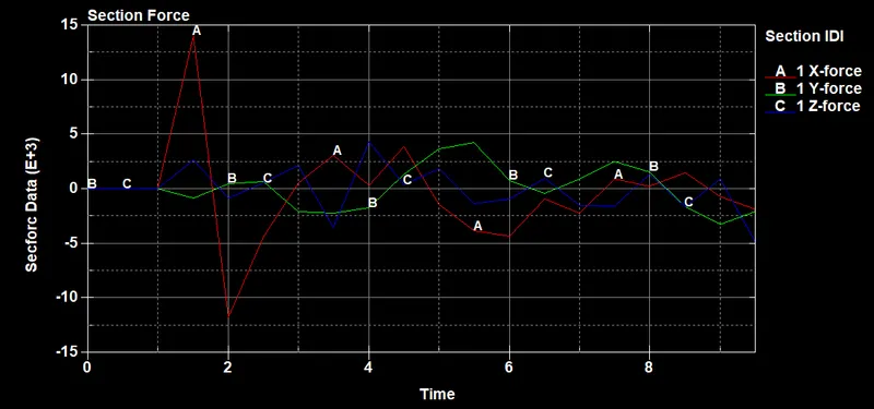
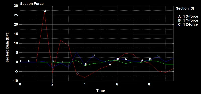
Cross - section force
- Beam element
- Solid element
 ..
..
Observing both the cases, the cross sectional force in the x direction is the highest. The cross section forces in the Y and Z direction are compartively lower. This makes sense, since the impact happens in the X direction, therefore,the cross section force in the X direction has highest peak in both the cases. Higher cross - section force is observed for the model with solid weld element . The cross sectional forces are greater beacause the solid adds stiffness to the component.
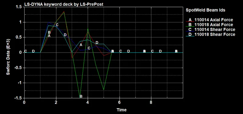
Spotweld forces:
- Beam element
- Solid element
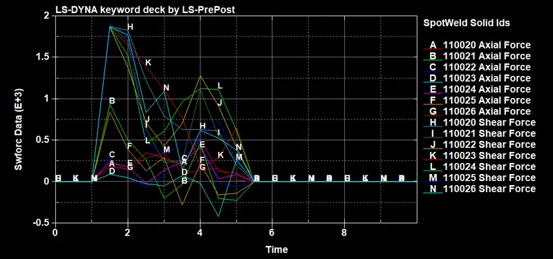
Observing the above plots, it can be inferred that the axial forces in the weld element are at peak in the model with beam weld and comparitvely the shear forces are smaller, whereas in case of model with solid hex weld element, the shear forces are comparitivley higher compared to axial forces. The beam element can take load in only one direction and the shear load that is applied in reality cannot be observed properly. Same can be observed from the plot of the grap of beam element. The solid element gives the resisting force in perpendicular direction to the c/s and therefore higher shear stress are observed for the solid element. Also it is observed that the solid element gives reasonable stress-strain plot compared to experimental test data.
- Conclusion:
Thus, the input deck file for connecting two parts using different weld elements and running a crash test is successfully created and completed with normal termination. The output data obtained are compared for both the cases. From the above comparison it can be observed that the solid elements show reasonable stress-strain results compared to beam weld element.