Week - 5 - Modelling Spotwelds
Aim:-
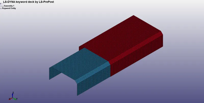
- The aim of this challenge is to model two kinds of spot welds one from beam elements and the other from solid elements and compare them for the below shell mesh.
Procedure:-
Spot weld with Beam Element:-
- The first step is to open the model in LS-Dyna Pre-post.
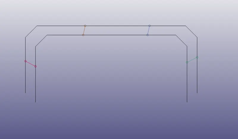
- The next step is to create beam elements using the element generate option.
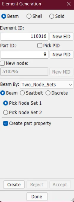
- A total of four beam elements has been created for the spot weld.
- After creating all the beam elements the respective part ID has been changed.
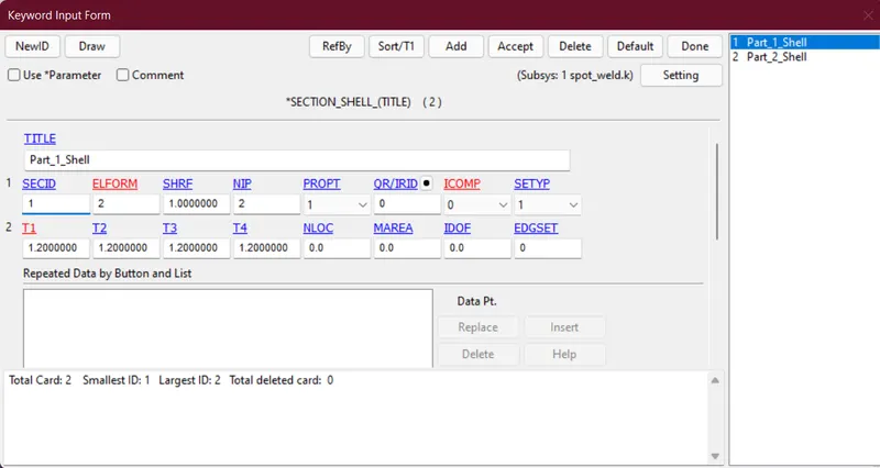
- Then to define section ID two types of section ID defined SHELL and BEAM.
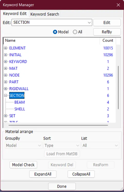
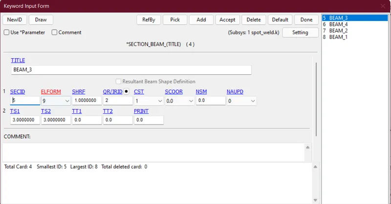
- Here we've selected element formulation of beam element as 9 which signifies the behaviour of spot weld as beam element.
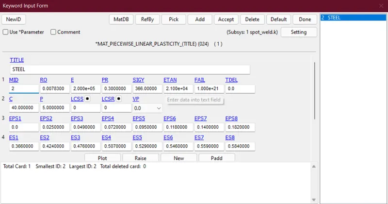
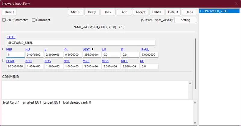
- Then create material properties both for weld parts and shell parts.
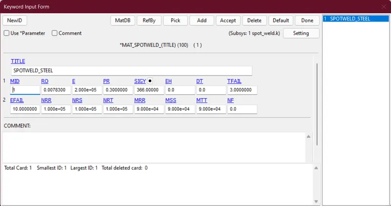
- The material property of the weld part is
- The material property of the shell part is
- The material property of the weld part is
- The next step is to assign all the respective material properties to the part ID.
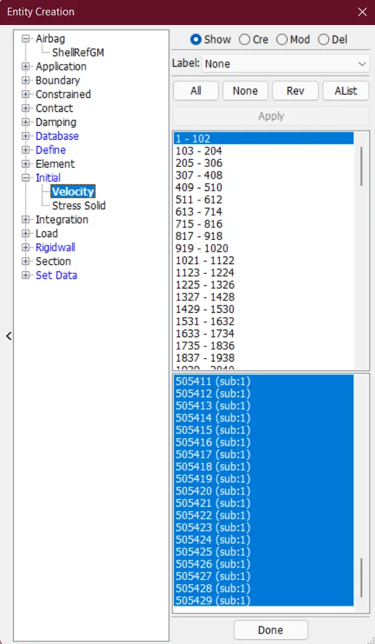
- The next step is to create a nodeset that includes all the parts and apply initial velocity using entity creation.
- Then we have to define contact cards for shell body for auto single surface contacts and one for spot weld(beam) element which is tied shell edge to edge contact card.
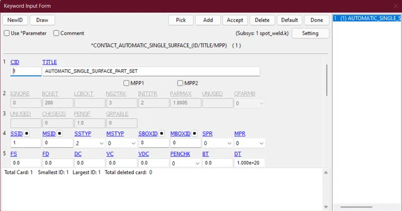
- In the above card, only a slave card is needed which is the part set of shell parts.
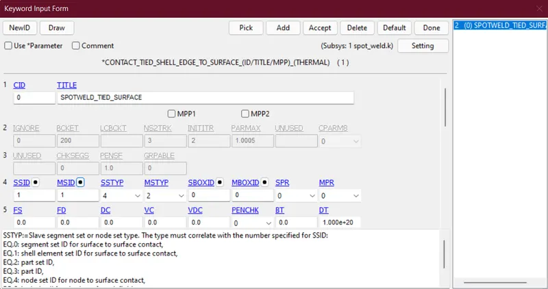
- In the above contact card, the slave card is given as an nodeset of spot weld beam elements and the master card is given as a part set of shell parts.
- Then define the databases like ascii, binary d3plot, history node.
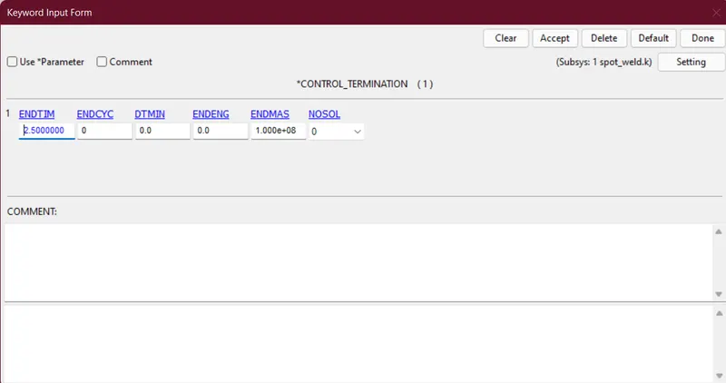
- Then define control termination with termination time is 2.5ms.
- The modeled spot weld with beam element is given below
- Post Processing:-
-
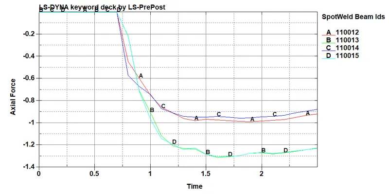
Axial force generated in the welds of the crashbox (along its length)
-
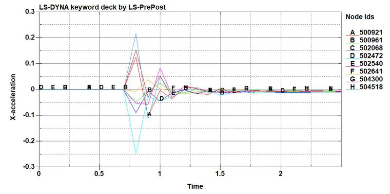
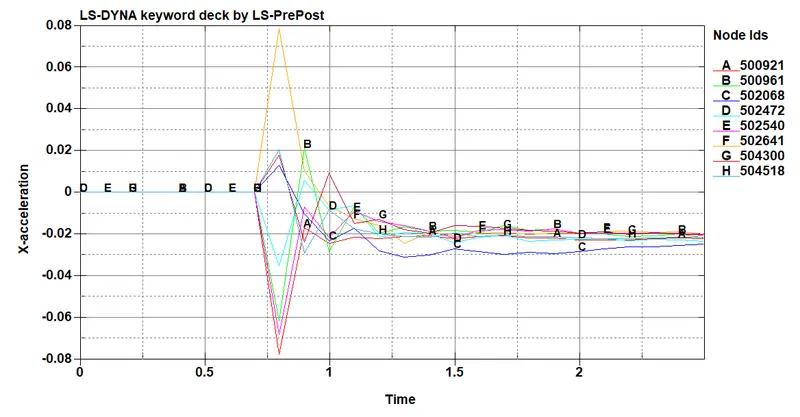
Acceleration plot of a node in the middle of the crashbox (along its length)
-
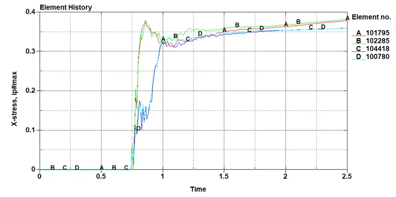
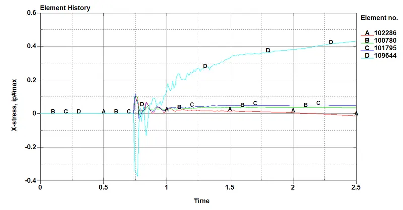
Maximum directional stress and strain along the length of the crashbox (X strain, Y strain etc)
- x-stress at adjacent to beam elements
- x-stress at adjacent to beam elements
-
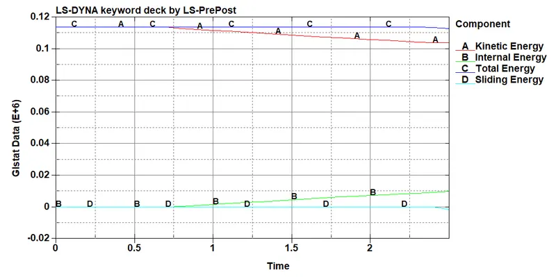
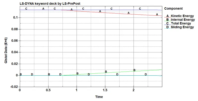
Plot of all energies (total, internal, kinetic, hourglass, sliding)
-
Spot weld with Solid Element:-
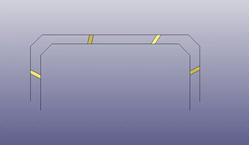
- First step is creating solid elements between the two shell parts using element editing option.
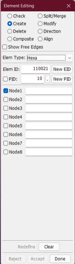
- The way to create solid element is, select four nodes of two shell element in such a manner that the desired solid element forms.
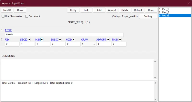
- The next step is to create section card for the hexa element.
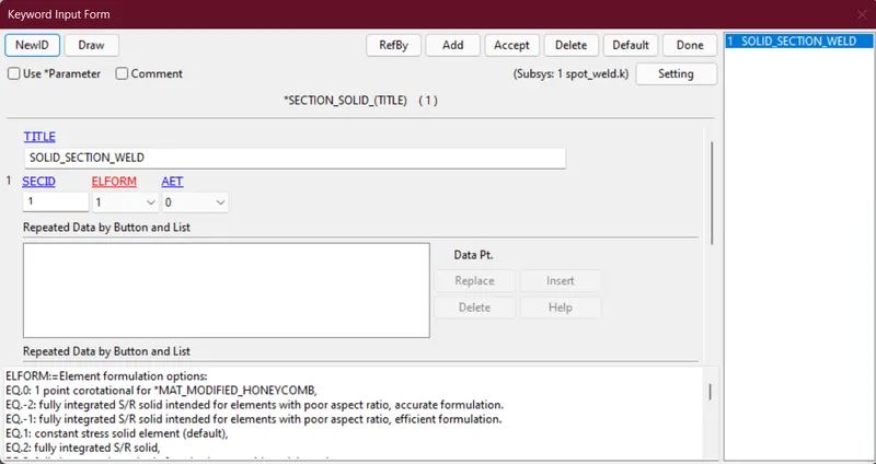
- Here we've selected the element formulation as 1 which is default for solid element.
- Then we've selected material property for the solid element and material selected is stee.
- Then assign the section Id and material Id in the part card.
- The next step is to create a nodeset that includes all the parts and apply initial velocity using entity creation.
- The next step is to assign contact cards which includes automatic single surface and spotweld card.
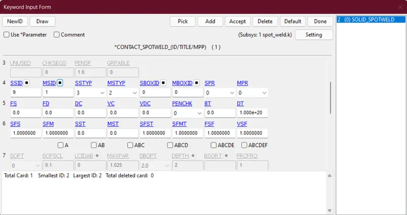
- In the above contact card we've selected hexa elements part as slave and shell part set as master.
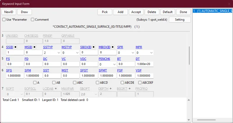
- In the above contact card we've considered shell part set as slave for automatic surface contacts.
- Then define the databases like ascii, binary d3plot, history node.
- Then define control termination with termination time is 2.5ms.
- The modeled spot weld with solid element is given below
- Post processing:-
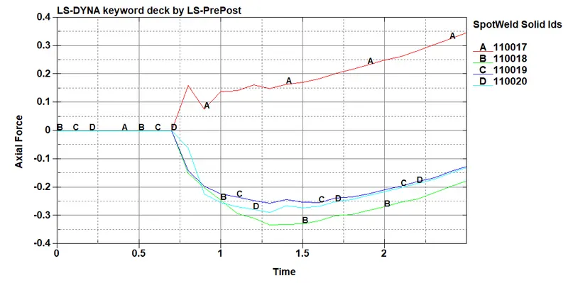
- Axial force generated in the welds of the crashbox (along its length)
- Acceleration plot of a welds in the crashbox (along its length)
- Maximum directional stress and strain along the length of the crashbox (X strain, Y strain etc)
- x-stress of elements adjacent to welds
- x-stress of elements adjacent to welds
- Plot of all energies (total, internal, kinetic, hourglass, sliding)
-
Compare the accelerations and stress/strain plots of two type of weld joints
- Acceleration
- Beam elements
- Solid elements
- Beam elements
- Stress
- Beam elements
- Solid elements
- Beam elements
- Acceleration
- Axial force generated in the welds of the crashbox (along its length)
Conclusion:-
- In this challenge I learnt about the processes to be followed for streamlineing the analysis procedure while working on a model.
- Got very much exposure in the engine file editing with script editor and reduced errors while running the simulation.