Week - 5 - Modelling Spotwelds
Aim: To create the spot weld using Beam and Solid element in Ls-Dyna and run the model to compare them and study the different way of modelling a spot weld in Ls-Dyna
THEORY:
Spot Welding is a type of resisting welding technique comes under the fusion welding category where heat and pressure both are applied in order to join two parts, the heat produced due to resistance of current flow through the material air gap, the heat generated is equal to I^2R and nugget formation happen
and then when held for few fractions of seconds the fusion between the part happens.
Spot weld strength plays a crucial importance to the overall vehicle structural integrity and crash safety. With the innovation of Advanced high strength steel (AHSS), prediction of spot-weld fracture is of paramount importance in current and future vehicle design.
Resistive spot welding (RSW) is the most common joining method in the automotive industry, particularly for BIW application. The main advantage of using RSW including high speed, low cost and the ability to volume automation. A typical vehicle contains approximately 2000-5000 spot welds. The joining strength is important to the overall structural integrity and vehicle crash safety.
Today automotive industry is mindful of reducing CO2 emissions an increasing fuel efficiency. To achieve these objectives, automakers are continuously working to reduce the overall vehicle weight.
Extensive use of Advanced high strength steel (AHSS) BIW is one of the ways to achieve this goal with the most recent innovation in AHSS, automotive industry has been able to use combination of low gage an high strength steel to design light weight body structure, However joining High-strength steel becomes challenging with lower gages, considering spot weld strength directly proportional to thickness of underlying sheet metal. Hence, spot-weld failure prediction during virtual design stage of vehicle development is of vital importance.
Constrained_SPOTWELD
The spot weld is a rigid beam that connects the nodal points of the nodal pairs; thus, nodal rotations and displacements are coupled. The spot welds must be connected to nodes having rotary inertias, that is, beams or shells. If this is not the case, for example, if the nodes belong to solid elements, use the option: *CONSTRAINED_RIVET. During implicit calculations this case is treated like a rivet, constraining only the displacements. Note that shell elements do not have rotary stiffness in the normal direction and, therefore, this component cannot be transmitted. Spot welded nodes must not have the same coordinates. Coincident nodes in a spot weld can be handled by the *CONSTRAINED_NODAL_RIGID_BODY option. Brittle and ductile failures are supported by this model. Brittle failure is based on the resultant forces acting on the weld, and ductile failure is based on the average plastic strain value of the shell elements which include the spot-welded node. Spot welds, which are connected to massless nodes, are automatically deleted in the initialization phase and a warning message is printed in the message file and the d3hsp file.
Note: Spot Weld Nodes and Constraints. Nodes connected by a spot weld cannot be members of another constraint set that constrain the same degrees-of freedom, a tied interface, or a rigid body, i.e., nodes cannot be subjected to multiple, independent, and possibly conflicting constraints.
Spot Weld Failure Criteria: Failure of Spot Weld occur when
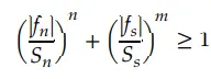
Where fn and fs are the normal and shear interface forces, component fn is the non-zero for tensile value only.
Sn is the normal force at spot weld failure
Ss is the shear force at spot weld failure
Fn is something that we can say generated force and the Sn is the limit basically that we specify
Failure Time: When the failure time, TF, is reached the spot weld becomes inactive and the constrained nodes may move freely.
Material Plastic Strain Failure: Spot weld failure due to plastic straining occurs when the effective nodal plastic strain exceeds the input value, εp fail. This option can model the tearing out of a spotweld from the sheet metal since the plasticity is in the material that surrounds the spot weld, not the spot weld itself. A least squares algorithm is used to generate the nodal values of plastic strains at the nodes from the element integration point values. The plastic strain is integrated through the element and the average value is projected to the nodes via a least square fit. This option should only be used for the material models related to metallic plasticity and can result is slightly increased run times. Failures can include both the plastic and brittle failures.
Modelling a Spotweld:
Crashworthiness is described as ability of vehicular structure to absorb kinetic energy and minimize injury to the passengers during collision, and is considered among the important criteria in determining vehicle design with regard to passenger safety.
There is a thin line between the Crash and Impact. Crash is also a type of impact, but when there is involvement of human beings then that study is termed as crash
The FE simulation helps engineer how components interact in an assembly and how the failure mode and mechanism is developed during impact loading.
Among many different possibilities to model a spot weld, in crashworthiness there are three modelling technique have been investigated , a single beam element, four hexahedron element and single hexahedron element, it is obvious the using beam element is the easiest discretization effort to model spot welds with finite elements, Here we found that the overall stiffness depends strongly on the position where the beam nodes are connected to the shell surfaces, secondly the torsion stiffness of beam can’t be activated, since the corresponding degree of freedom is not available in the attached shell formulation.
Considering the spot weld discretization with four hexahedron elements, the smallest element size would decrease the time step too much and additional mass to counterbalance this by using mass scaling is not acceptable.
The third modelling technique consists of one single hexahedron, here the available option were found not accurate enough in most cases.
Procedure:
- Import the model first in ls-dyna
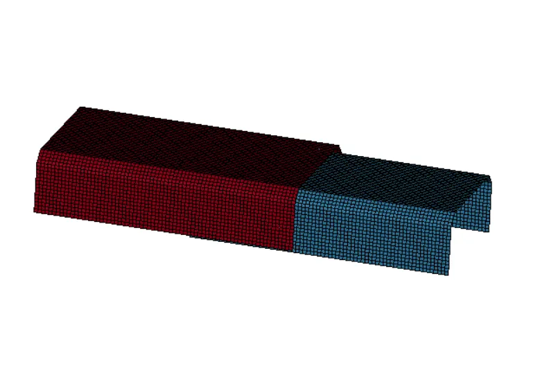
Here we not only have to create the spotweld, we also need to setup the impact or crash scenario, such that this assembly will striking with rigid-wall with velocity of 13.88 mm/ms approximately equal to 50kmph
- Modeling a Rigid-wall
Rigid wall are basically analytical representation of surfaces or volumes, frequently used to represent the stiff structure in FE modelling, that are either stationary or in motion
A stationary planar rigid-wall is created ahead of the frontal portion of crashing model at an approximate distance, go to Create entity >> Rigid wall, define node on the front portion of crash model, and also translate it away from the structure somewhat around 5 to 7 units (General Recommendation is that there should be some gap between the body and the rigid wall). The model is made to hit the rigid-wall at an impact velocity of 13.88mm/ms
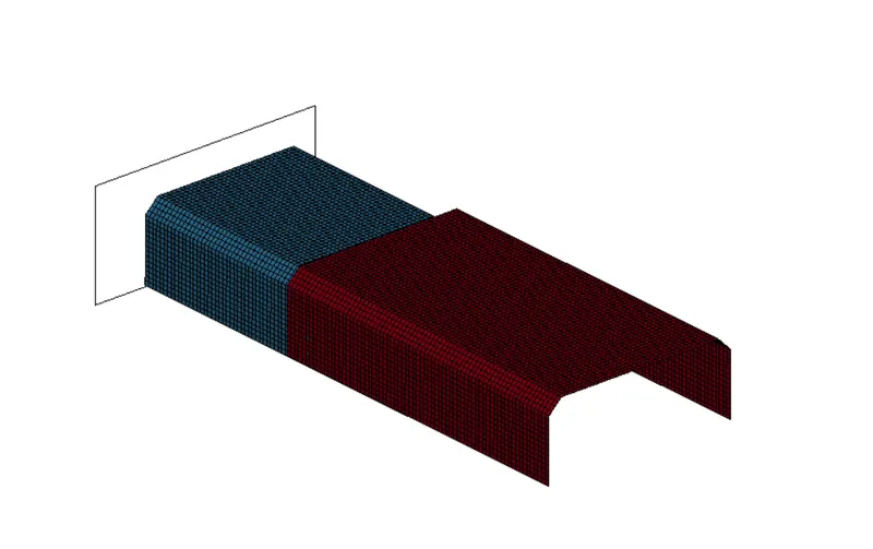
Rigid wall creation
- Defining an Initial Velocity
Now next step is to define the initial velocity for impact, for that first we need to create a set of nodes, and after that go to Keyword >> Initial >> Velocity
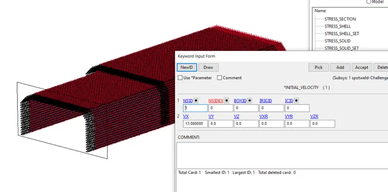
Defining Initial Velocity to the model
- Creating a spot weld by using beam element
To create a spot weld using beam element go to Element Tool >> Element editing >> Beam, then select two nodes between which beam is created
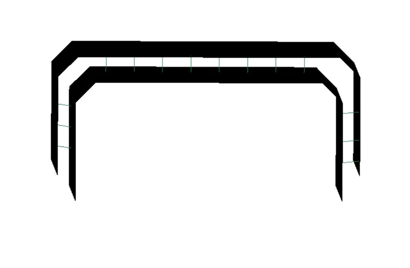
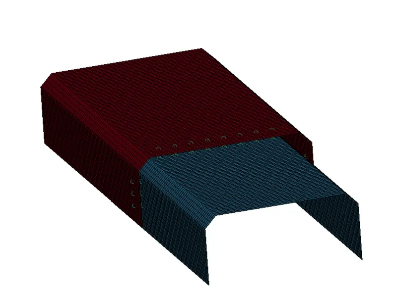
Creating a Spot Weld using Beam Element
- Now after creating the Spotweld by using beam, we need to define the Material Section and Contact for the Spot weld, first we define the contact for the spot-weld
Contact in LS-DYNA is defined using contact surfaces, it is useful in order to avoid the penetration among the part. Most impact and crash simulation require self-contact to be defined, a self-contact is established in our model for both the top and bottom shell using *AUTOMATIC_SINGLE_SURFACE contact card. Single surface contact is most general type of contact used in Ls-Dyna program that searches all the external surface within a model to determine any penetration has occurred, also *CONTACT_SPOTWELD card is used to define the contact interface between spotwelds that are created in specified location and the shell part (top and bottom)
For that go to Keyword >> Contact >> CONTACT_TIED_SHELL_EDGE_TO_SURFACE, between the plate and the spotweld
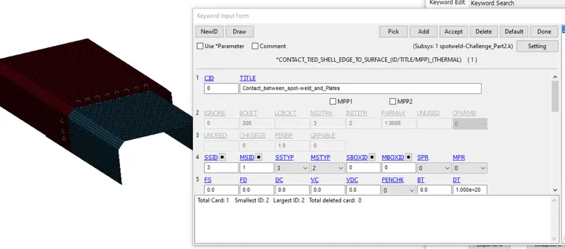
Defining Contact between Spot-weld and Shell Surface
Also, we have to define the Self contact, so that the part after deformation should not penetrate itself, for that again go to keyword >> Contact >> AUTOMATIC_SINGLE_SURFACE
Here we only have to define the Slave nodes, for that we create the Part set and then define as a slave
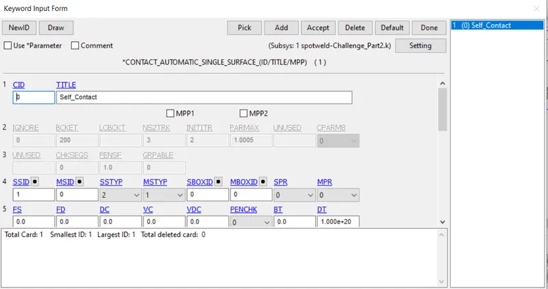
Self-Contact
Defining a Cross-section to extract the forces transferred
For creating a cross-section first, we need to create a node set and shell set
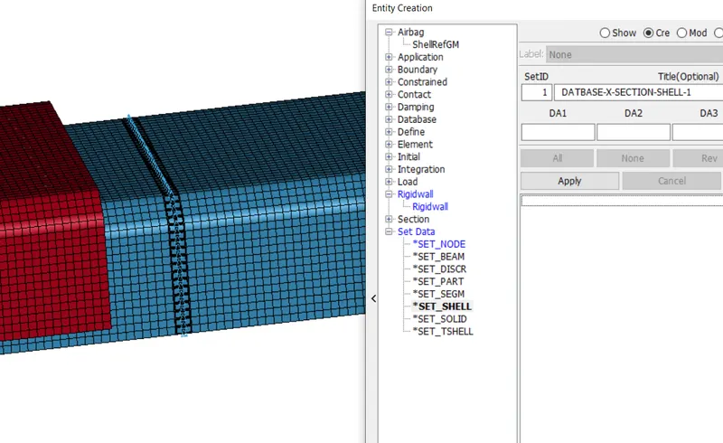
Defining Shell set id for Crosssection
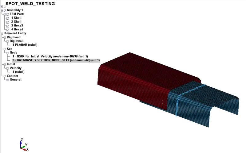
Defining Node set id for Cross-section
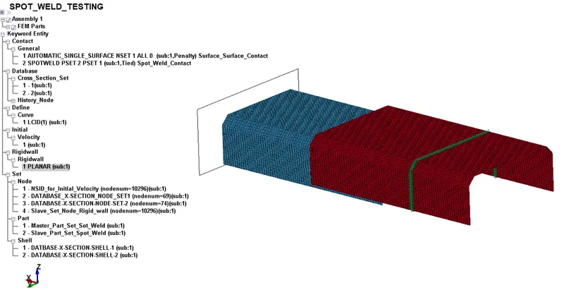
Cross-section is defined
Material setup:
Although many materials exist for metal the most robust model is *MAT_024 or *MAT_PIECEWISE_LINEAR_PLASTICITY.
The material model is the standard workhouse and is the recommended starting point for elastic-plastic deformation of metals and general plastics, since it can also handle viscoelastic behavior.
The Spot Weld with beam and solid element are model with *MAT_100 or *MAT_SPOTWELD material card.
Here we don’t know the exact property of spot weld, so we need to define the time base failure in order to analyze the behavior of spot-weld during failure. In this case we use steel as our material for both the metal plates and the spot weld, the plastic portion is defined by the curve between effective stress vs effective strain.

*MAT_24 IS DEFINED FOR METAL PLATE
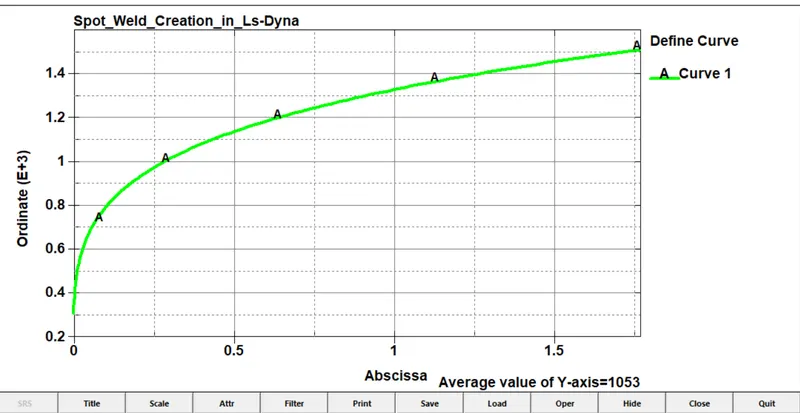
Non-Linear Portion is defined by using curve
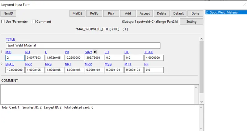
*MAT_100 is defined for spotweld
Section setup for both shell and Spot weld element
The metal sheet defined the shell thickness of 2mm, the spot weld is made up of beam element and modeled with beam section with appropriate cross-section (tublur) CST =1 and using an element formulation ELFORM_9 (especially for spotweld beam elements)
The spotweld made up of solid element are modelled with solid section with an element formulation ELFORM_1
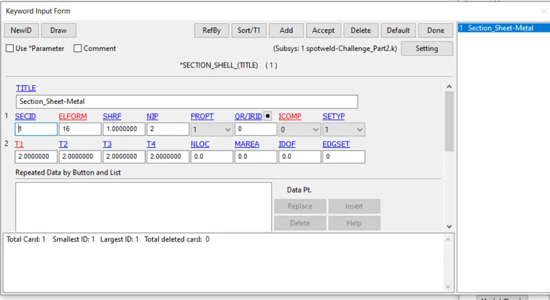
Section for Sheet Metals
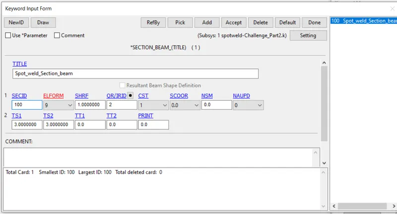
Section for Spotweld
- Now after creating the section and material for spotweld and the plate, the next step is to define it for the plate and Spotweld
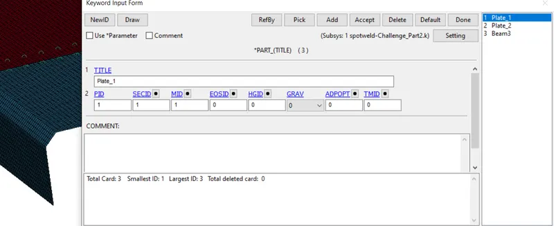
Defining Material and Section for the Spotweld and the plates
- To run the simulation properly we need to create the control card, without creating control card simulation will not start, and the most important one is termination card, which will define the running time for the simulation. Control Hourglass energy, Accuracy, Energy.
The simulation is run for 20ms and the spotweld timing is defined as 4ms during the simulation in order to analyze the behavior.
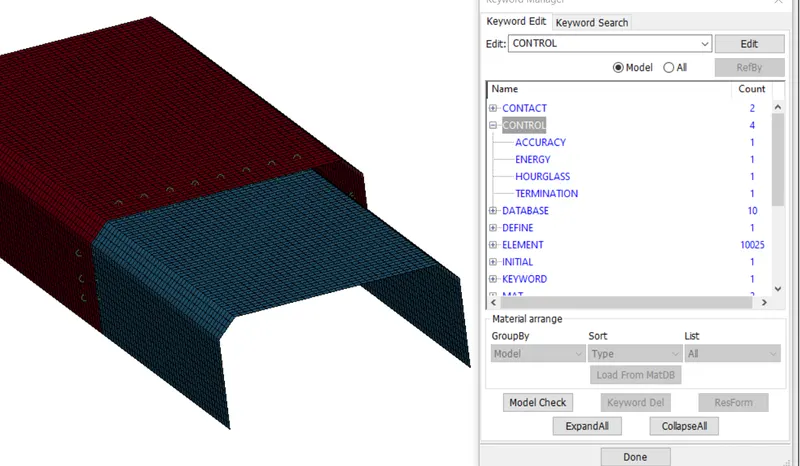
Defining control cards
- Now our initial setup is done, now we need to define the output, for that go to Keyword >> binary d3 plot, this is the main animation file also we need to request the ASCII output as well and in it contains the result of GLSTAT, MATSUM, RCFORC, etc.
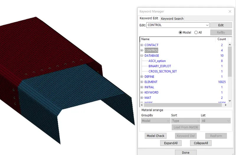
Defining ASCII and Binary output
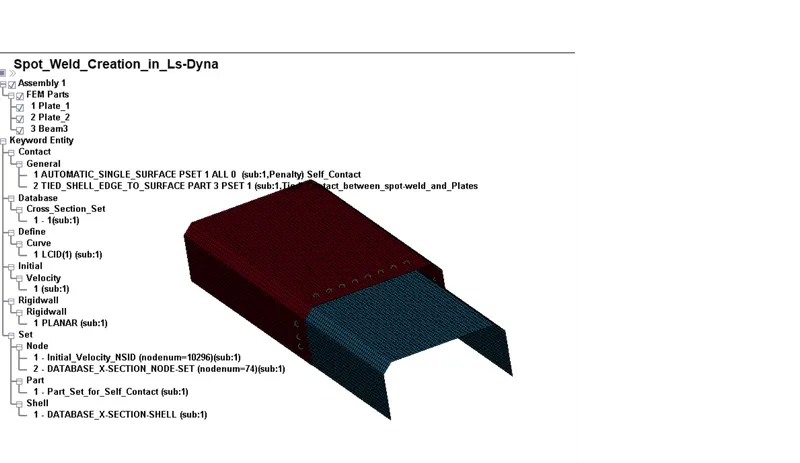
Defining the complete Deck-setup
Model Checking and Solving the setup
One of the most important pre-processing task is to ensure the validity of CAE model before submitting it to the solver for solution.
A good and rich suite of check reduces engineering errors, increases confidence in the simulation results and minimize the duration of simulation cycle by eliminating multiple back and forth from the solver to pre-processor
- Now our deck setup is completely, now one thing left is only to check the file, whether there is any error present or not, if present then remove those error before giving them to solve in solver.
- After that we can save the file, but before that one important thing is to check the error before solving the file, if error is present then file is not able to solved by the solver, so make sure to solve all the error and after that save the file,
- After saving the file, the next step is to open the file in Notepad and edit or give the title and add Keyword ID, because it is a general practice and it is recommended, so that file and their result will not mismatch, otherwise if we don’t follow this then there are more chances of mismatch of results, if you do slightly change in the condition and you don’t know which result or d3 plot belong to which, so it is recommended to give them title and Keyword id so that, our result should coming up with proper name.
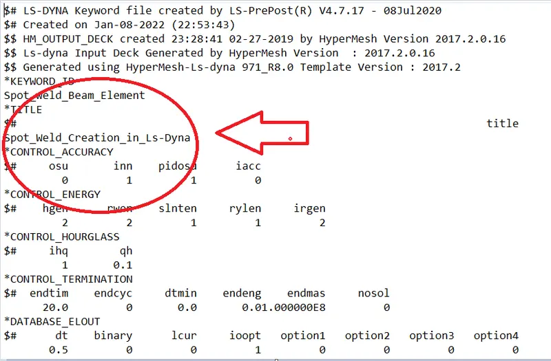
Giving a proper Title and keyword id to file
- Now our file is ready for solving. To solve the file, open the Ls-Dyna Run and import the file here and then run the file for solving, it will show you how much time it take to solve the file, after solving the file it will gives you result in the form of the input we define like main animation file like Binary d3 plot
- Now we got lot of files in the form of result, but our main file is the d3 plot which is a binary file, we can open it in any editor, but this file is not readable, but we have ASCII file which we can open it in notepad, but it is readable, so we again open the LS-Dyna and then open the dyna binary file in it.
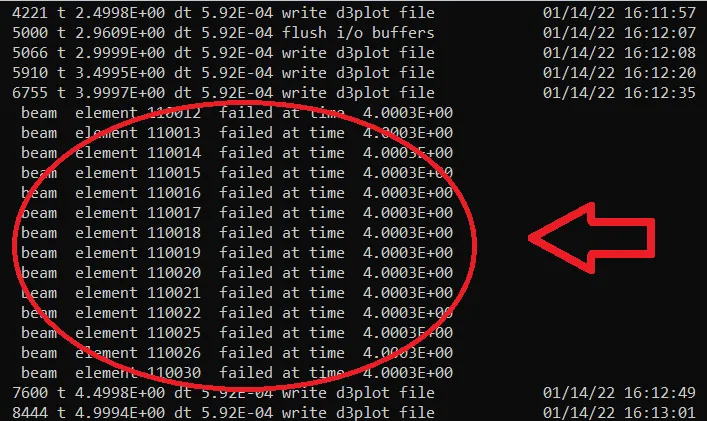
Failure of Spotweld at time 4 ms
Spotweld Failure in Ls-Dyna
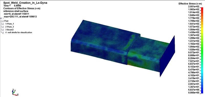
Von-misses Stress
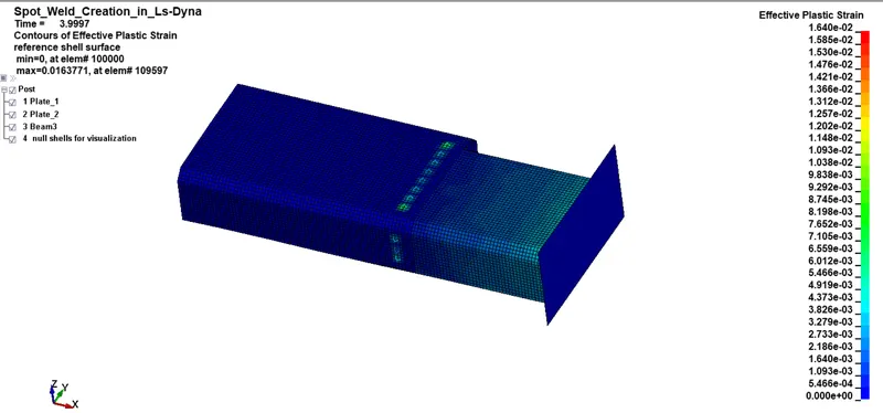
Effective Plastic strain
Case 2:
In similar manner we have to create the Spotweld by using the Hexa element, again we have to look for the create entity option to create the Hexa element and then define material and section to the Hexa element
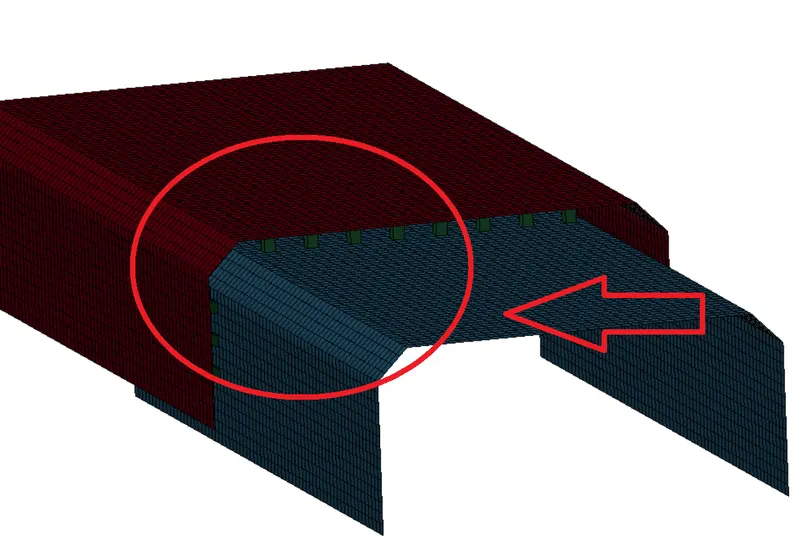
Spotweld is defined by using Hexa element
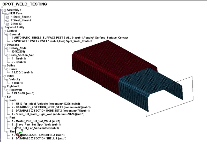
Defining the complete Deck-setup
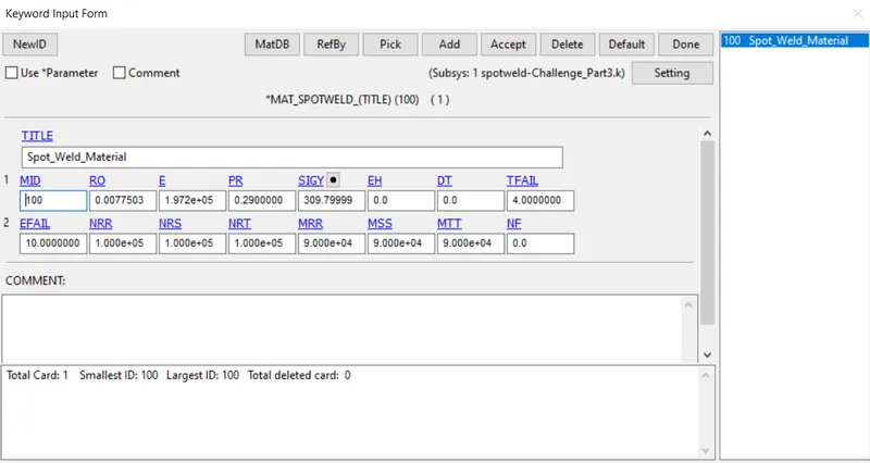
Spotweld Material
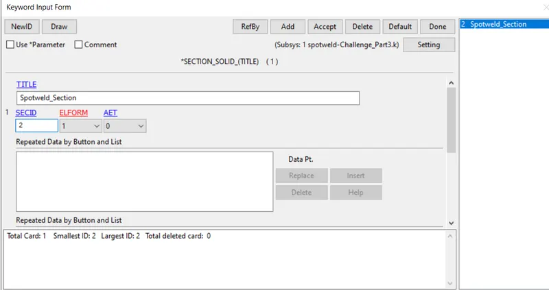
Section for Hexa Element
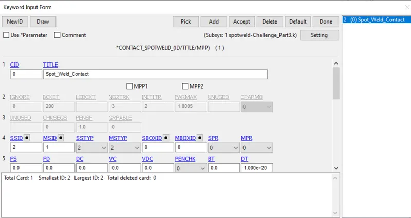
Spotweld contact is defined for Hexa element
- In similar way we have to define or follow the same procedure as that of Case 1 and extracting result out form it
Spotweld Failure in Ls-Dyna
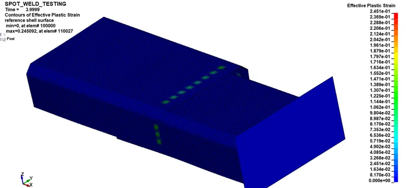
Effective Plastic Strain
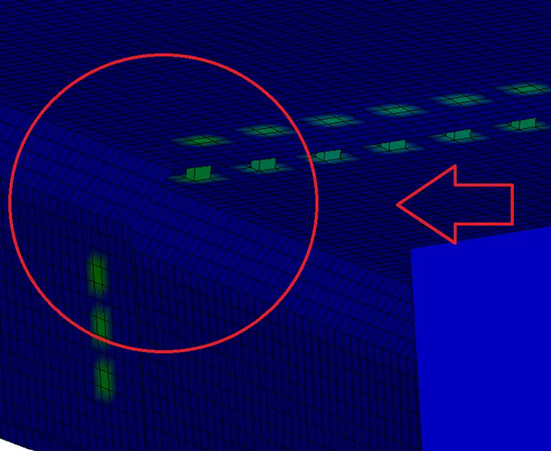
Spotweld (Hexa elements) connecting two plates
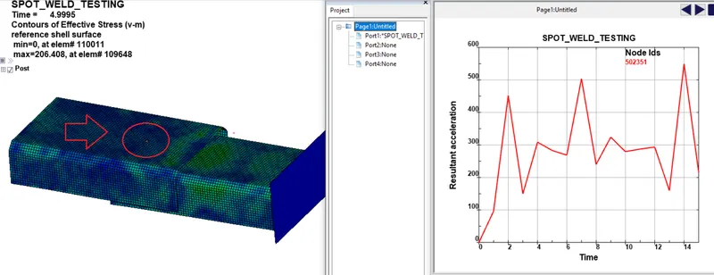
Nodal Resultant acceleration
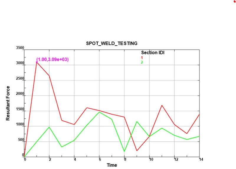
Cross-section results
Cross-section 1 belong to the plate which comes in contact with Rigidwall, and cross-section belong to plate 2 which is tied with plate 1 using Spotweld.
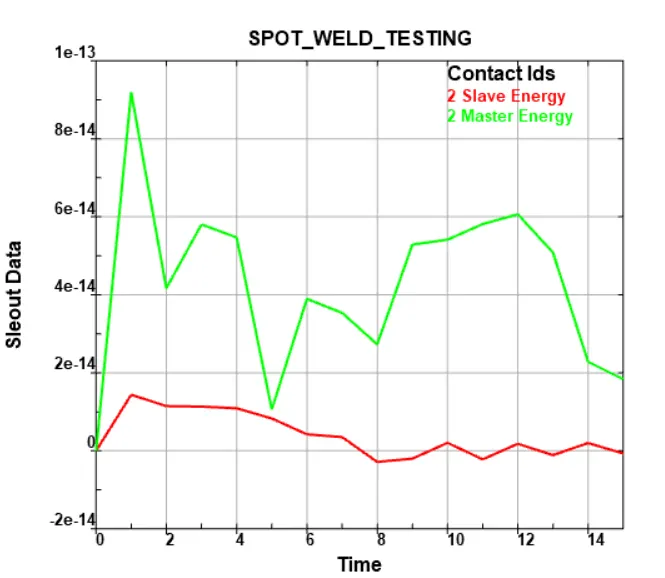
Contact Energy for Spot-weld contact
SWFORC: To find Spotweld Axial and Normal forces
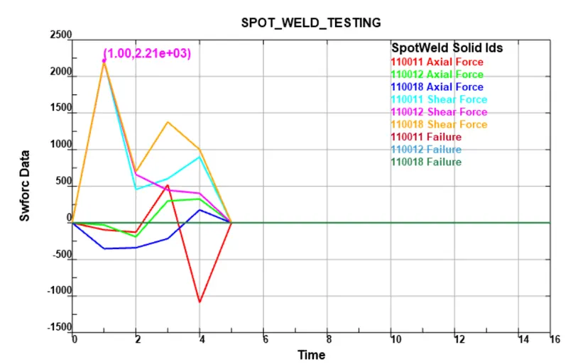
Axial and Shear forces experienced by Beam Element
Forces value drop to Zero when the Spot weld will fail
Beam vs Solid Element in Spotweld
Here the study is carried out by modeling the spot weld using Beam and Solid element, as you see here the value of shear stress is more as compare to the Axial value, because of loading and Boundary condition, But in case of Beam element the Axial value is somewhat more than the Shear force value, as beam is only able to take load in only one direction, that is Axial direction, we can’t realistically see the shear load applied. So to make proper representation of weld it has to be a solid element, and element property matters a lot.
SpotWeld Without Failure
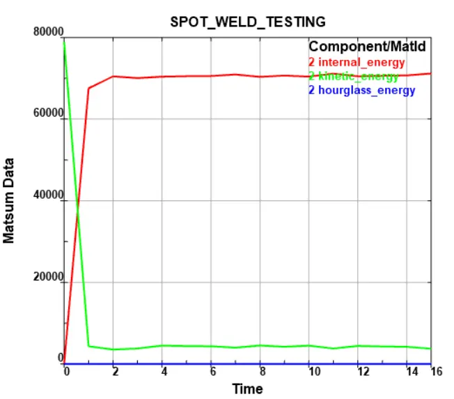
Internal Energy vs Kinetic Energy vs Hourglass Energy
Cross-section result
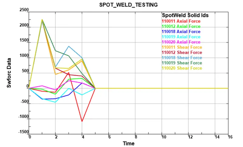
Axial Force / Shear Force
Leaning Outcome:
- The spot weld are modeled using Beam and Solid element for the same component
- The material card and all other keyword are properly defiend for the Spotweld and the Plates
- The simulation is caried out with time dependent failure
- The component are bounces back after impacting on the rigidwall