Week - 5 - Modelling Spotwelds
AIM:
To model spot welds for the given assembly and simulate crash test.
Case 1: Beam_Spot_weld
Case 2: Solid_Spot_weld
OBJECTIVES:
• To define spot welds using beam and solid elements.
• To create a solver deck to perform the crash test simulation.
• To enter the values in g mm ms unit system.
• To assign steel material properties for the crash box and rigidwall for the rigid wall.
• To assign initial velocity for the crash box at 50kmph.
• To create contact card.
• To create control keywords.
• To measure the cross section force generated at the spot weld.
• To plot the total, internal, kinetic, hourglass, sliding energy graphs.
• To compare the results with the beam and solid spot weld elements.
• To run the .K file and evaluate the results.
UNIT SYSTEM USED: G MM MS
BOUNDARY CONDITIONS:
• The crash box should crash onto the rigidwall.
• Material of crash box is Steel and that of weld is Spotweld.
• Initial velocity of crash box is 20mm/ms.
MATERIAL PROPERTIES:
• Crash Box:
Density: 0.0078g/mm3
Youngs Modulus (E): 210000g/mm*ms2
Poissons Ratio: 0.3
Yield Strength: 350 g/mm*ms2
PROCEDURE:
CASE 1: BEAM_SPOT_WELD
• Importing:
• FILE > OPEN > LS DYNA KEYWORD FILE > SPOTWELD_ASSIGNMENT.
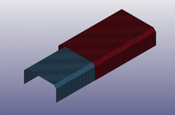
• Then, go to MODEL AND PART COMMAND > KEYWORD MANAGER.
• We can check the keywords in the model.
• Part Check:
• Go to MODEL AND PART COMMAND > PART DATA.• We can see that the model consists of 2 part i.e. top and bottom layer.
• Now, rename the parts as top and bottom layer.
• Now, in the part card we have to define section and material, so let’s create a Section and Material card.
• *Beam_Spotweld:
• Go to MESH > ELEMENT GENERATION > BEAM > BY TWO_NODE_SETS > SELECT THE 1ST NODE > SELECT THE 2ND NODE > CREATE > DONE.
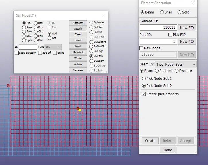
• Similarly, create 5 beam elements between the shell parts as defined.
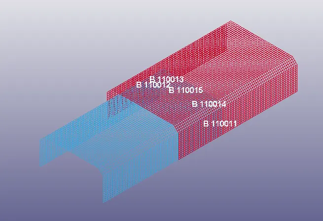
• *Section:
• Go to MODEL AND PART COMMAND > KEYWORD MANAGER > ALL > SECTION > SHELL > TITLE = SECT_SHELL > SECID = 1 > T1 = 1.5 > ACCEPT > DONE.
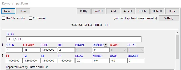
• This will create a shell section which can be defined for the shell parts.
• Go to MODEL AND PART COMMAND > KEYWORD MANAGER > ALL > SECTION > BEAM > TITLE = BEAM_SPOTWELD > SECID = 2 > ELEMFORM = 9 > QR/IRID = 4 > T1 = 3 > ACCEPT > DONE.
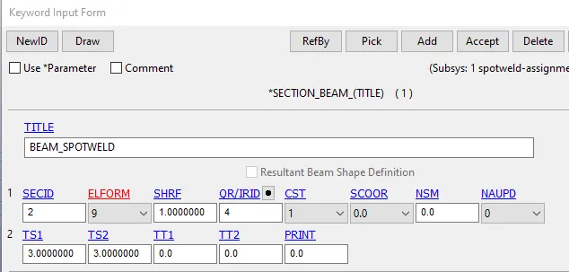
• This will create a beam section for the beam spot weld.
• *Material:
• Go to MODEL AND PART COMMAND > KEYWORD MANAGER > ALL > MATERIAL > 001-ELASTIC > TITLE = STEEL_SHELL_MAT > MID = 1 > RO = 7.85E-3 > E = 2.1E5 > PR = 0.3 > ACCEPT > DONE.
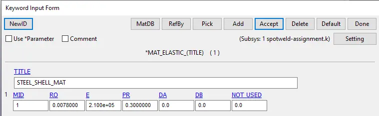
• This will create elastic steel material for the shell parts.
• Go to MODEL AND PART COMMAND > KEYWORD MANAGER > ALL > MATERIAL > 100-SPOTWELD > TITLE = MAT_SPOT_WELD > MID = 2 > RO = 7.85E-3 > E = 2.1E5 > PR = 0.3 > SIGY = 100 > TFAIL = 0 > EFAIL = 15 > NRR = 6000 > NRS = 6000 > NRT = 1.5E4 > MRR = 9E4 > MSS = 9E4 > MTT = 9E4 > ACCEPT > DONE.
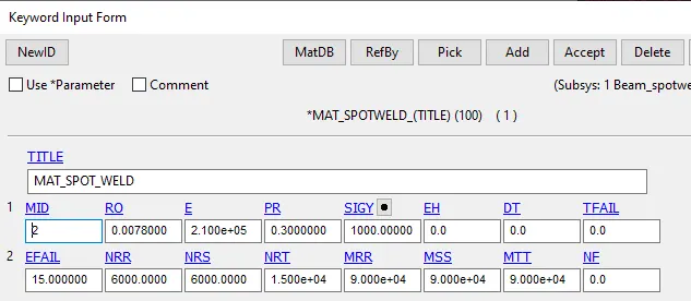
• This will create spot weld material for the beam elements. Here, the spotweld failure is dependent on the Axial and Shear forces limit, TFAIL is not used.
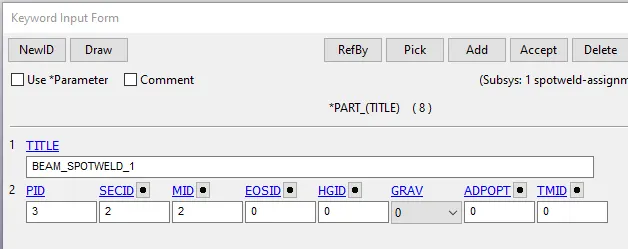
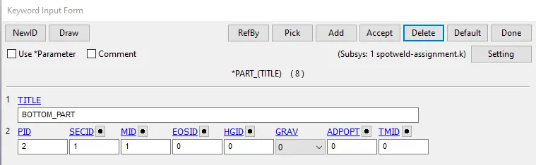
• Now, go to MODEL AND PART COMMAND > KEYWORD MANAGER > MODEL > PART > ASSIGN > SECTION AND MATERIAL.
• *Rigid_wall_planar:
• Go to, MODEL AND PART COMMAND > KEYWORD MANAGER > ALL > RIGIDWALL > PLANAR > XT = -20MM > ACCEPT > DONE.
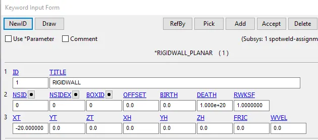
• This will create a rigidwall plane at 20mm distance from the crash box.
• *Initial_Velocity:
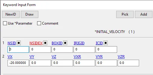
• Now, we have to define initial velocity for the Crash box.
• Go to, MODEL AND PART COMMAND > KEYWORD MANAGER > ALL > INITIAL > VELOCITY > NSID = 1 > VX = -20 MM/MS > APLLY > DONE.
• *Set_node:
• Go to CREATE ENTITY > SET > NODE LIST > DB-XSECT > SPOTWELD_NSET > MODEL > DISP > ACCEPT > DONE.
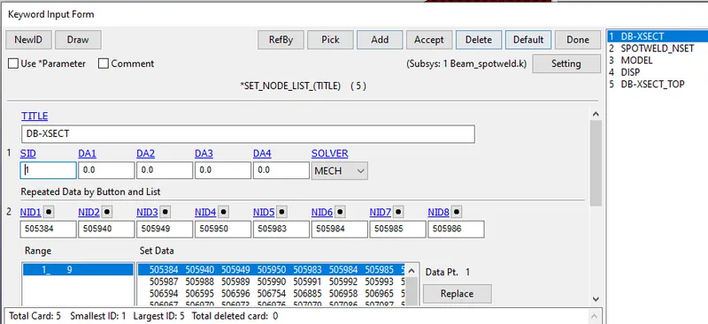
• Create node set for all the above titles.
• Similarly, create shell set and part sets.
• *Contact_Automatic_Single_Surface:
• Now, we have to define Contact for the crash box.
• Go to, MODEL AND PART COMMAND > KEYWORD MANAGER > CONTACT > AUTOMATIC_SINGLE_SURFACE > CID =2 > TITLE = SINGLE_SURFACE_PART_SET > SSTYP = 2 > SSID = 1> ACCEPT > DONE.
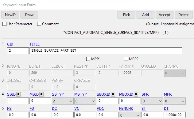
• This will define the contact as Slave for the Cell_Phone and Master for the Rigid_wall.
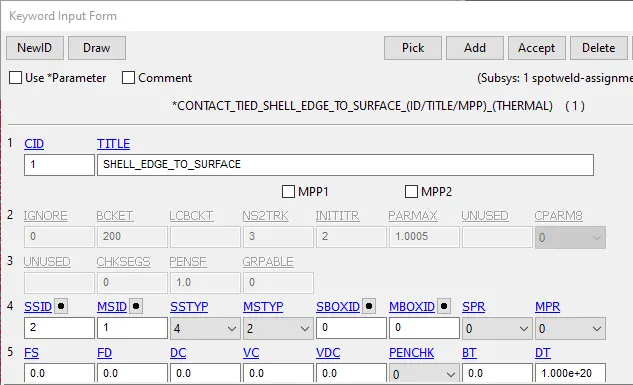
• Go to, MODEL AND PART COMMAND > KEYWORD MANAGER > CONTACT > TIED_EDGE_SHELL_TO_SURFACE > SSTYP = 4 > SSID = 2 > MSTYP = 2 > MSID = 1 > ACCEPT > DONE.
• *Control_Termination:
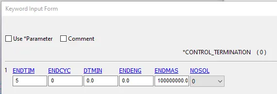
• Now, we have to define Control_Termination card for the simulation time.
• Go to, MODEL AND PART COMMAND > KEYWORD MANAGER > CONTROL > TERMINATION > ENDTIM = 5 MS > ACCEPT > DONE.
• *Database_Binary_D3plot:
• Go to, MODEL AND PART COMMAND > KEYWORD MANAGER > DATABASE > BINARY D3PLOT > DT = 0.1 > ACCEPT > DONE.
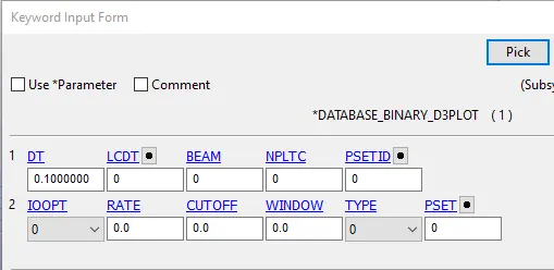
• This will create the binary D3plot output files.
• *Database_ASCII:
• And finally we have to define the output results.
• Go to, MODEL AND PART COMMAND > KEYWORD MANAGER > DATABASE > ASCII > GLSTAT > DT = 0.1 MS > MATSUM > DT = 0.1 > RCFORC = 0.1 > SLEOUT = 0.1 > SWFORC = 0.1 > ACCEPT > DONE.
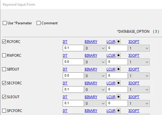
• This will provide the output results.
• *Database_Cross_Section_Set:
• Go to, MODEL AND PART COMMAND > KEYWORD MANAGER > DATABASE > CROSS_SECTION_SET > CSID = 1 > PICK > PLANE.
• This will create a cross section plane in the middle of the crash box.
• Model check:
• The final step is to perform Model check.
• Go to, MODEL AND PART COMMAND > MODEL CHECK > DONE.
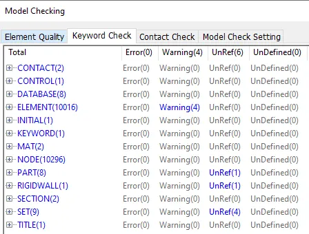
• Save the file as BEAM_SPOTWELD.
• LS_Run:
• Now, open LS RUN > OPEN THE FILE > RUN.
• The solver will solver the model and check for the Normal Termination message at the end of the solver screen.
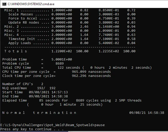
Post-Processing:
CASE 1: BEAM_SPOT_WELD
• Open LS Pre-Post.
• FILE > OPEN > BEAM_SPOTWELD > LS DYNA BINARY PLOT.
• Go to, POST > FRINGE COMPONENT > STRESS > VON MISSES > DONE.
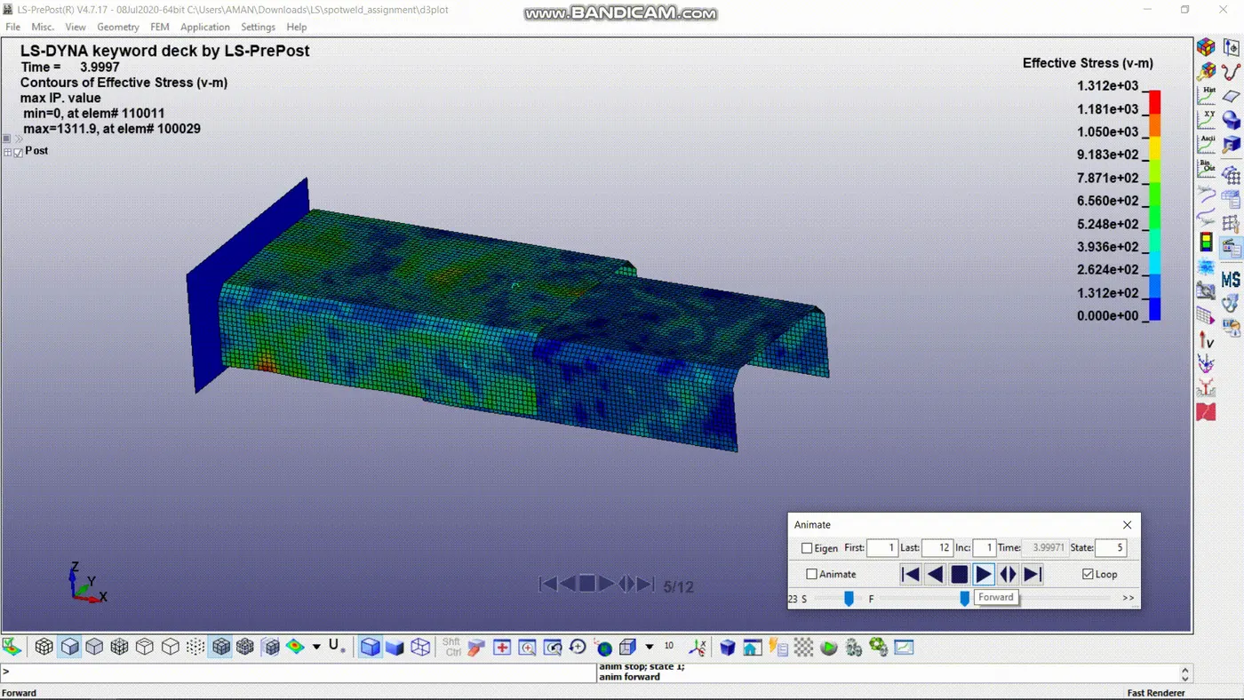
• To plot the Energy graphs go to, POST > ASCII > LOAD FILE > GLSTAT > SELECT ENERGIES > PLOT > DONE.
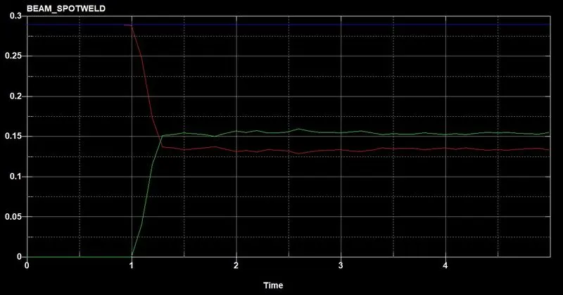
- The energy graph shows kinetic energy is converted into internal energy upon collision.
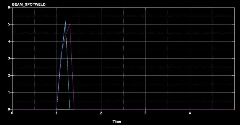
- The axial force value increases upto 5 before the element fails.
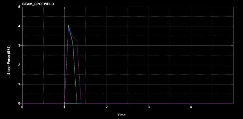
- The shear force value increases upto 4 before the faiure occurs.
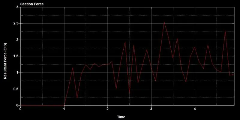
- This shows the cross section force on the shell part.