Modelling Spotwelds
AIM:
To model spot welds for the given assembly and simulate crash test.
Case 1: Beam_Spot_weld
Case 2: Solid_Spot_weld
OBJECTIVES:
• To define spot welds using beam and solid elements.
• To create a solver deck to perform the crash test simulation.
• To enter the values in g mm ms unit system.
• To assign steel material properties for the crash box and rigidwall for the rigid wall.
• To assign initial velocity for the crash box at 50kmph.
• To create contact card.
• To create control keywords.
• To measure the cross section force generated at the spot weld.
• To plot the total, internal, kinetic, hourglass, sliding energy graphs.
• To compare the results with the beam and solid spot weld elements.
• To run the .K file and evaluate the results.
UNIT SYSTEM USED: G MM MS
BOUNDARY CONDITIONS:
• The crash box should crash onto the rigidwall.
• Material of crash box is Steel and that of weld is Spotweld.
• Initial velocity of crash box is 20mm/ms.
MATERIAL PROPERTIES:
• Crash Box:
Density: 0.0078g/mm3
Youngs Modulus (E): 210000g/mm*ms2
Poissons Ratio: 0.3
Yield Strength: 350 g/mm*ms2
PROCEDURE:
CASE 1: BEAM_SPOT_WELD
• Importing:
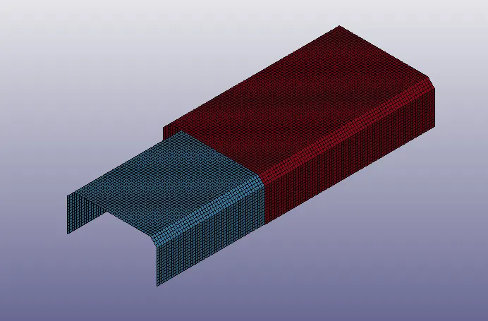
• FILE > OPEN > LS DYNA KEYWORD FILE > SPOTWELD_ASSIGNMENT.
• Then, go to MODEL AND PART COMMAND > KEYWORD MANAGER.
• We can check the keywords in the model.
• Part Check:
• Go to MODEL AND PART COMMAND > PART DATA.• We can see that the model consists of 2 part i.e. top and bottom layer.
• Now, rename the parts as top and bottom layer.
• Now, in the part card we have to define section and material, so let’s create a Section and Material card.
• *Beam_Spotweld:
• Go to MESH > ELEMENT GENERATION > BEAM > BY TWO_NODE_SETS > SELECT THE 1ST NODE > SELECT THE 2ND NODE > CREATE > DONE.
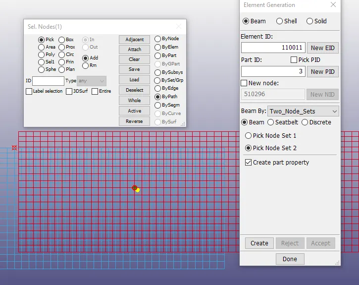
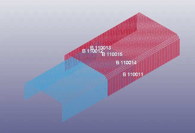
• Similarly, create 5 beam elements between the shell parts as defined.
• *Section:
• Go to MODEL AND PART COMMAND > KEYWORD MANAGER > ALL > SECTION > SHELL > TITLE = SECT_SHELL > SECID = 1 > T1 = 1.5 > ACCEPT > DONE.
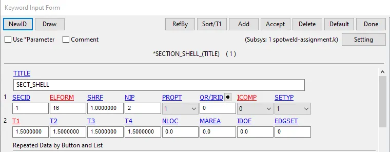
• This will create a shell section which can be defined for the shell parts.
• Go to MODEL AND PART COMMAND > KEYWORD MANAGER > ALL > SECTION > BEAM > TITLE = BEAM_SPOTWELD > SECID = 2 > ELEMFORM = 9 > QR/IRID = 4 > T1 = 3 > ACCEPT > DONE.
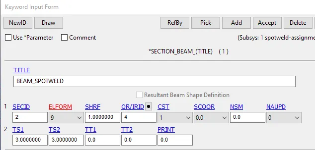
• This will create a beam section for the beam spot weld.
• *Material:
• Go to MODEL AND PART COMMAND > KEYWORD MANAGER > ALL > MATERIAL > 001-ELASTIC > TITLE = STEEL_SHELL_MAT > MID = 1 > RO = 7.85E-3 > E = 2.1E5 > PR = 0.3 > ACCEPT > DONE.
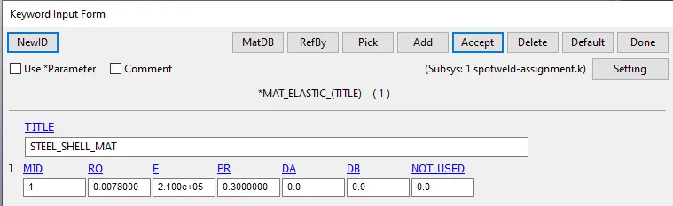
• This will create elastic steel material for the shell parts.
• Go to MODEL AND PART COMMAND > KEYWORD MANAGER > ALL > MATERIAL > 100-SPOTWELD > TITLE = MAT_SPOT_WELD > MID = 2 > RO = 7.85E-3 > E = 2.1E5 > PR = 0.3 > SIGY = 100 > TFAIL = 0 > EFAIL = 15 > NRR = 6000 > NRS = 6000 > NRT = 1.5E4 > MRR = 9E4 > MSS = 9E4 > MTT = 9E4 > ACCEPT > DONE.
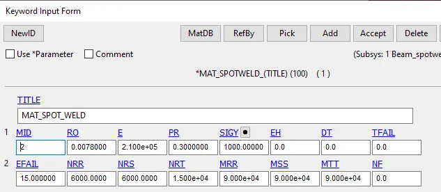
• This will create spot weld material for the beam elements. Here, the spotweld failure is dependent on the Axial and Shear forces limit, TFAIL is not used.
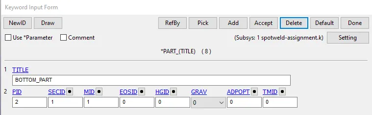
• Now, go to MODEL AND PART COMMAND > KEYWORD MANAGER > MODEL > PART > ASSIGN > SECTION AND MATERIAL.
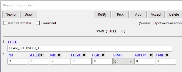
• *Rigid_wall_planar:
• Go to, MODEL AND PART COMMAND > KEYWORD MANAGER > ALL > RIGIDWALL > PLANAR > XT = -20MM > ACCEPT > DONE.
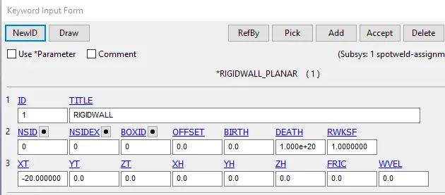
• This will create a rigidwall plane at 20mm distance from the crash box.
• *Initial_Velocity:
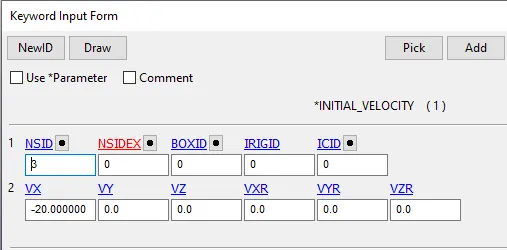
• Now, we have to define initial velocity for the Crash box.
• Go to, MODEL AND PART COMMAND > KEYWORD MANAGER > ALL > INITIAL > VELOCITY > NSID = 1 > VX = -20 MM/MS > APLLY > DONE.
• *Set_node:
• Go to CREATE ENTITY > SET > NODE LIST > DB-XSECT > SPOTWELD_NSET > MODEL > DISP > ACCEPT > DONE.
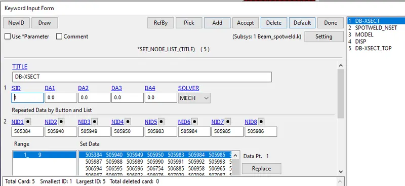
• Create node set for all the above titles.
• Similarly, create shell set and part sets.
• *Contact_Automatic_Single_Surface:
• Now, we have to define Contact for the crash box.
• Go to, MODEL AND PART COMMAND > KEYWORD MANAGER > CONTACT > AUTOMATIC_SINGLE_SURFACE > CID =2 > TITLE = SINGLE_SURFACE_PART_SET > SSTYP = 2 > SSID = 1> ACCEPT > DONE.
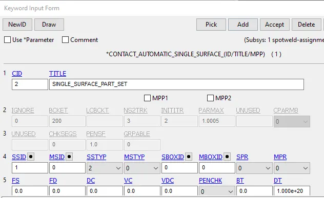
• This will define the contact as Slave for the Cell_Phone and Master for the Rigid_wall.
• Go to, MODEL AND PART COMMAND > KEYWORD MANAGER > CONTACT > TIED_EDGE_SHELL_TO_SURFACE > SSTYP = 4 > SSID = 2 > MSTYP = 2 > MSID = 1 > ACCEPT > DONE.
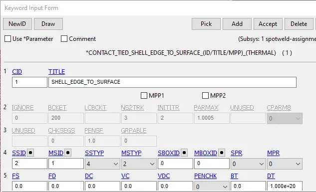
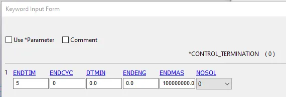
• *Control_Termination:
• Now, we have to define Control_Termination card for the simulation time.
• Go to, MODEL AND PART COMMAND > KEYWORD MANAGER > CONTROL > TERMINATION > ENDTIM = 5 MS > ACCEPT > DONE.
• *Database_Binary_D3plot:
• Go to, MODEL AND PART COMMAND > KEYWORD MANAGER > DATABASE > BINARY D3PLOT > DT = 0.1 > ACCEPT > DONE.
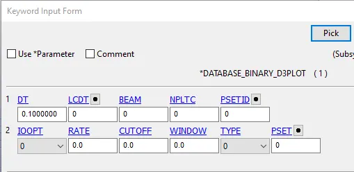
• This will create the binary D3plot output files.
• *Database_ASCII:
• And finally we have to define the output results.
• Go to, MODEL AND PART COMMAND > KEYWORD MANAGER > DATABASE > ASCII > GLSTAT > DT = 0.1 MS > MATSUM > DT = 0.1 > RCFORC = 0.1 > SLEOUT = 0.1 > SWFORC = 0.1 > ACCEPT > DONE.
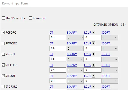
• This will provide the output results.
• *Database_Cross_Section_Set:
• Go to, MODEL AND PART COMMAND > KEYWORD MANAGER > DATABASE > CROSS_SECTION_SET > CSID = 1 > PICK > PLANE.
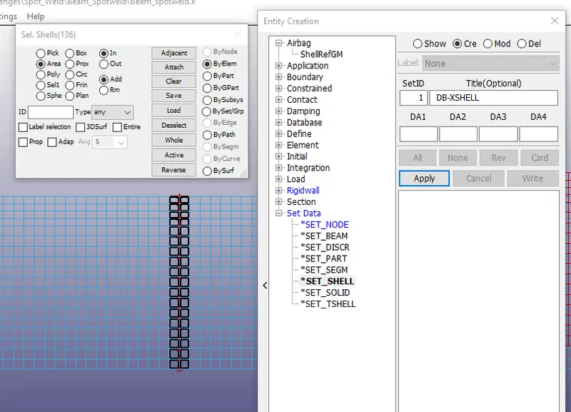
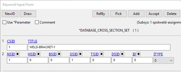
• This will create a cross section plane in the middle of the crash box.
• Model check:
• The final step is to perform Model check.
• Go to, MODEL AND PART COMMAND > MODEL CHECK > DONE.
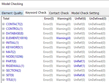
• Save the file as BEAM_SPOTWELD.
• LS_Run:
• Now, open LS RUN > OPEN THE FILE > RUN.
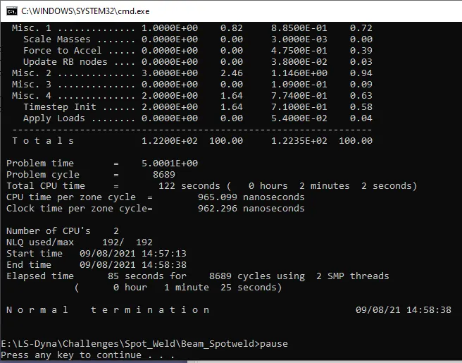
• The solver will solver the model and check for the Normal Termination message at the end of the solver screen.
CASE 2: SOLID_SPOTWELD
• Open the BEAM_SPOTWELD K file and delete the beam elements.
• *Element_Solid:
• Now, go to MODEL AND PART > ELEMENT > SOLID > EID = 1 > PICK > NODES > ACCEPT > DONE.
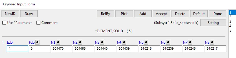
• Similarly, create 4 solid elements as in the beam spotweld.
• *Section_Solid:
• Go to SECTION > SOLID > TITLE > SPOTWELD > SECID = 2 > ELFORM = 1.
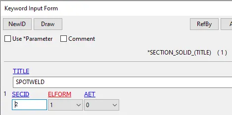
• This will create the solid section for the spotweld.
• Save the file as SOLID_SPOTWELD.
• Here, the whole setup remains the same just we replace the beam element with solid element.
• LS_Run:
• Now, open LS RUN > OPEN THE FILE > RUN.
• The solver will solver the model and check for the Normal Termination message at the end of the solver screen.
Post-Processing:
CASE 1: BEAM_SPOT_WELD
• Open LS Pre-Post.
• FILE > OPEN > BEAM_SPOTWELD > LS DYNA BINARY PLOT.
• Go to, POST > FRINGE COMPONENT > STRESS > VON MISSES > DONE.
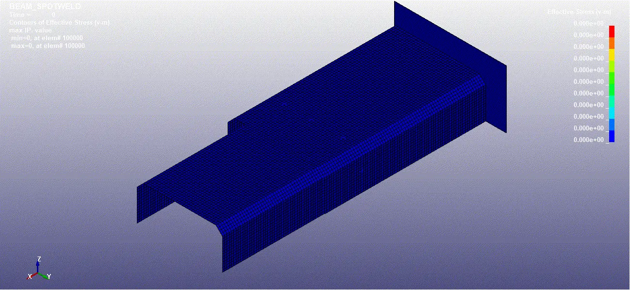
• To plot the Energy graphs go to, POST > ASCII > LOAD FILE > GLSTAT > SELECT ENERGIES > PLOT > DONE.
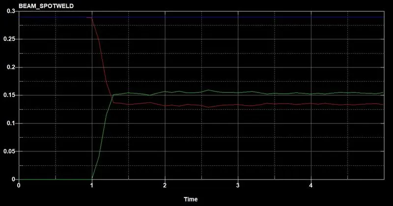
- The energy graph shows kinetic energy is converted into internal energy upon collision.
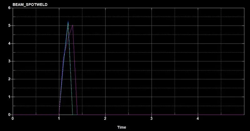
- The axial force value increases upto 5 before the element fails.
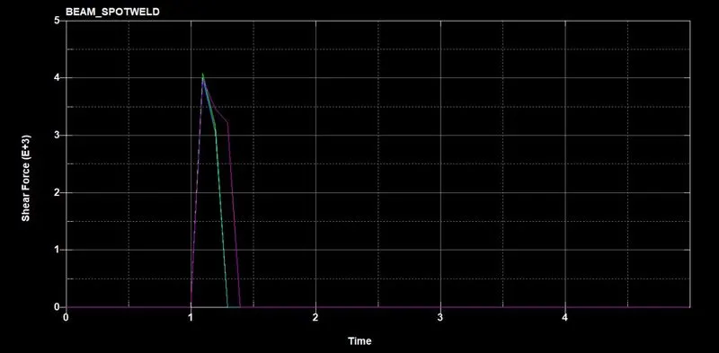
- The shear force value increases upto 4 before the faiure occurs.
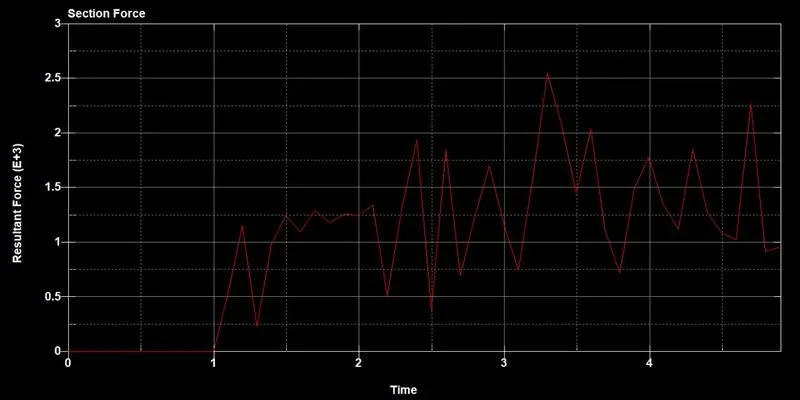
- This shows the cross section force on the shell part.
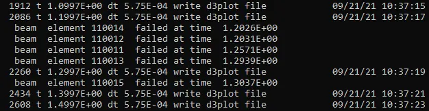
- Beam element failure -
• This will plot the energy graph for the model.
CASE 2: SOLID SPOTWELD
• Open LS Pre-Post.
• FILE > OPEN > BEAM_SPOTWELD > LS DYNA BINARY PLOT.
• Go to, POST > FRINGE COMPONENT > STRESS > VON MISSES > DONE.
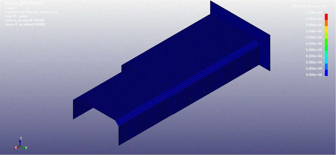
• To plot the Energy graphs go to, POST > ASCII > LOAD FILE > GLSTAT > SELECT ENERGIES > PLOT > DONE.
• This will plot the energy graph for the model.
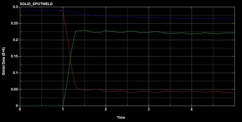
- The energy graph shows kinetic energy is converted into internal energy upon collision.
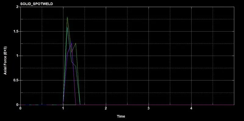
- The axial force value increases upto 1.75 before the element fails.
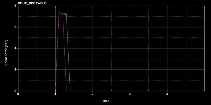
- The shear force value increases upto 7.5 before the faiure occurs.
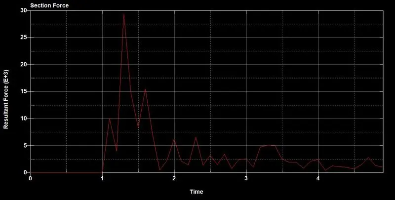
- This shows the cross section force on the shell part.
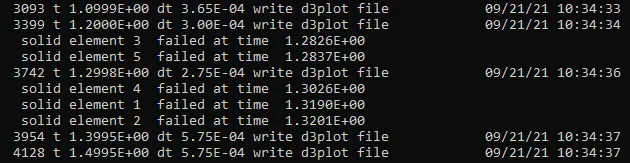
- Beam element failure -
LEARNING OUTCOMES:
• To import the Keyword file.
• To check the model for parts data and keyword manager.
• To assign keywords for the model.
• To create beam and solid spotweld elements.
• To define section and material properties for the parts.
• To define rigid wall.
• To define boundary conditions.
• To define initial velocity.
• To define the output results.
CONCLUSION:
By performing this project we conclude that, the beam spotweld elements bear less resultant force when compared to the solid element which bear more resultant force.
Hence, the model is simulated for both beam and solid spotweld elements for axial and shear based failure and the elements failure is simulated.