Week - 5 - Modelling Spotwelds
AIM: To create a spotweld and run the simulation by giving the parameters.
Procedure:
- The component is shown below. On that component we have create spotwelds at given line in symmetric manner.
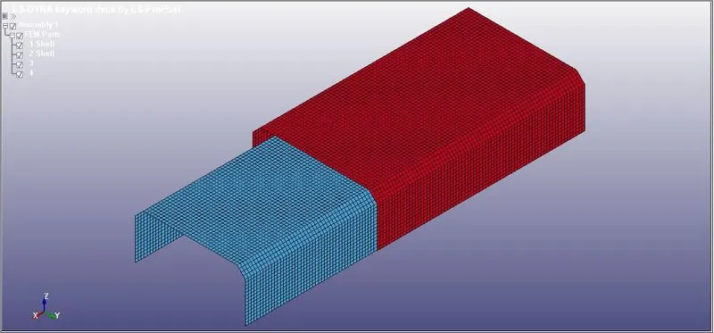
- To create a spotweld we have to first create a beam and then apply the property of spotweld to that beam.
- To create beam go to MESH>EleGen
- Select the beam and select Two_Sets_Node for selecting the points for beam.
- We will create 4-5 beam at different for to see the Spotweld behaviour.
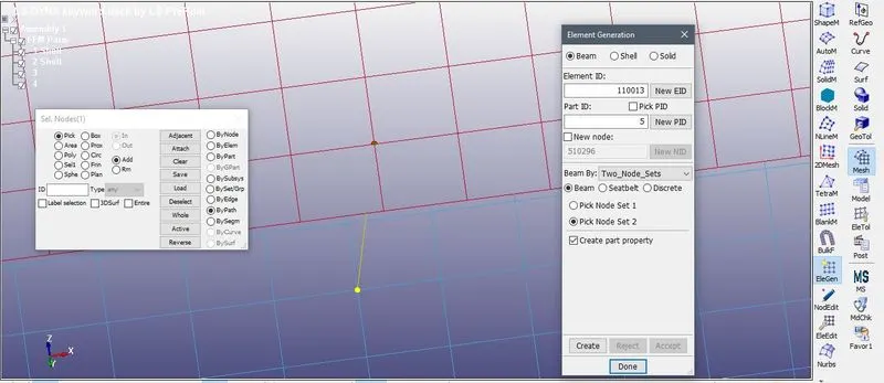
- After creating different beam at different points:
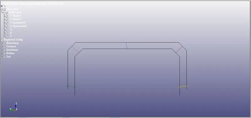
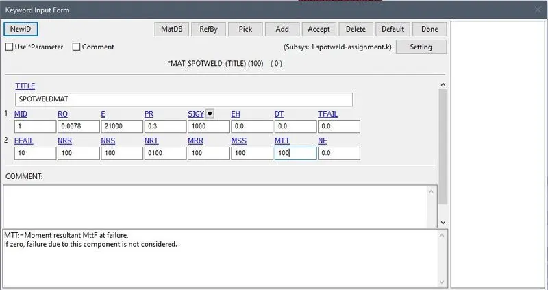
- Now the beam is created we will add material to the beam for that go to the MODEL>KEYWRD>MAT>SPOTWELD
- And add all the required parameters to it.
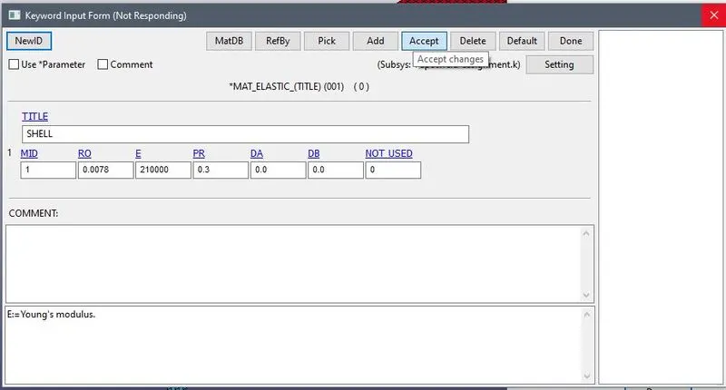
- Also we will add material to the Shell element for this we will use 001 ELASTIC material.
SPOTWELD
SHELL
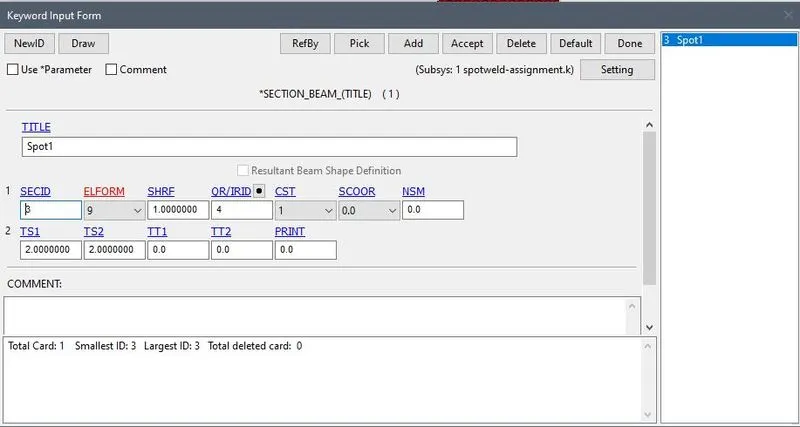
- Now we will create a section for this for that go to MODEL>KEYWRD>SECTION>BEAM
- Here for spotweld we will use ELFORM=9. And thickness 2mm.
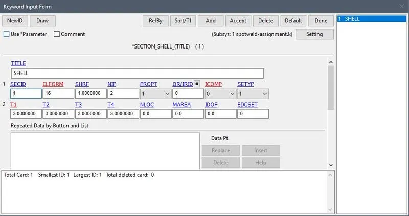
- Same for shell we use SHELL SECTION with ELFORM=16 with thickness 3 mm.
SPOTWELD
SHELL
- Now we assign this parameters to the PART

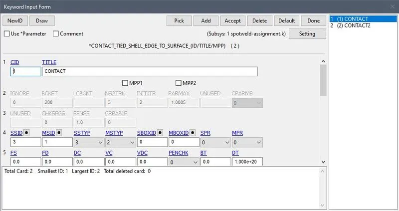
- Now we will create contact between SHELL and SPOTWELD , For this we will use TIGHT SHELL EDGE TO SURFACE contact.
- MODEL>KEYWRD>CONTACT>TIGHT_SHELL_EDGE_TO_SURFACE
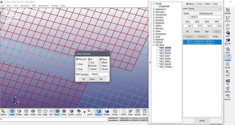
- But before that we have to select the SET_NODE and SET_PART for the MASTER AND SLAVE PART
- For that MODEL>CREENT>SETDATA>SET_NOTE and SET_PART
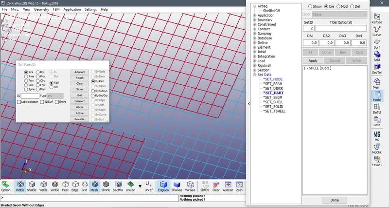
CONTACT:
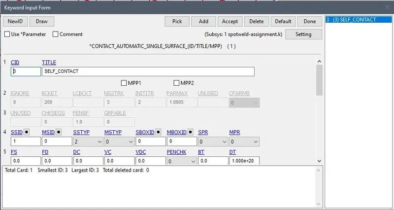
- Now we will create another contact in which the SHELL element is a SLAVE for this we will use AUTOMATIC_SINGLE_SURFACE_CONTACT
- Now we have apply the boundary condition to the shell element so for one shell we will apply SPC boundary condition and for other we will apply PRESCRIBED_MOTION.
- MODEL>CreEnt>BOUNDARY>BCS
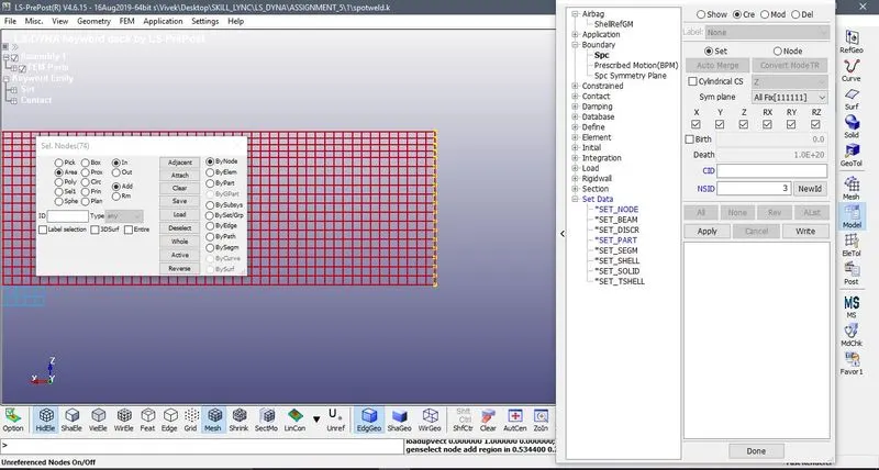
- MODEL>KEYWRD>BOUNDARY>PRESCRIBED_MOTION
- But before that we have to create SET_NODE data.
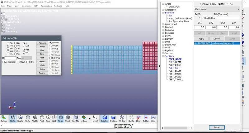
- We have to create Curve for this.
PRESCRIBED MOTION:
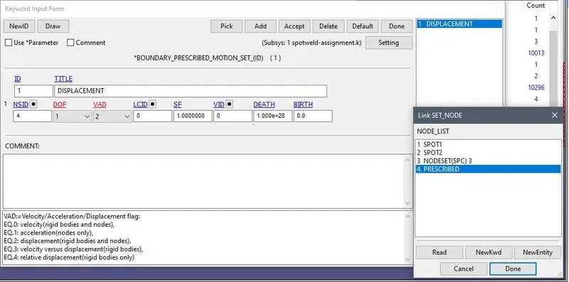
- Here VAD is 2 because we required displacement.
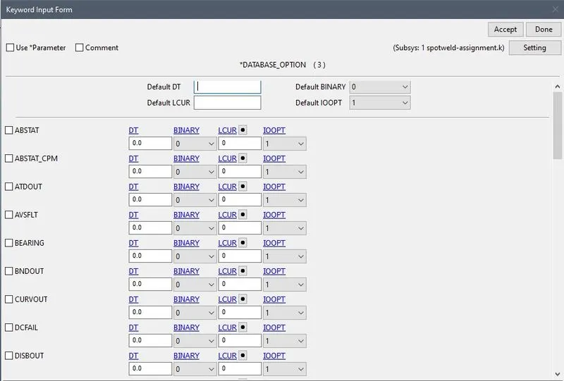
- Now for the Output go to the MODEL>KEYWRD>DATABASE>ASCII_OPTION
- And we will select GLSTAT for different energies, SWFORCE for spotweld , NODOUT with DT=1.
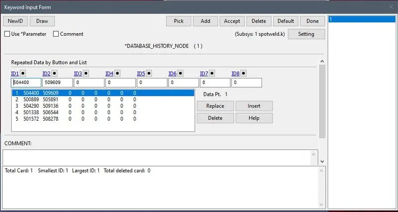
- To get the NODOUT data we have to create a card MODEL>KEYWRD>DATABASE>HISTORY_NODE and add the number of the node.
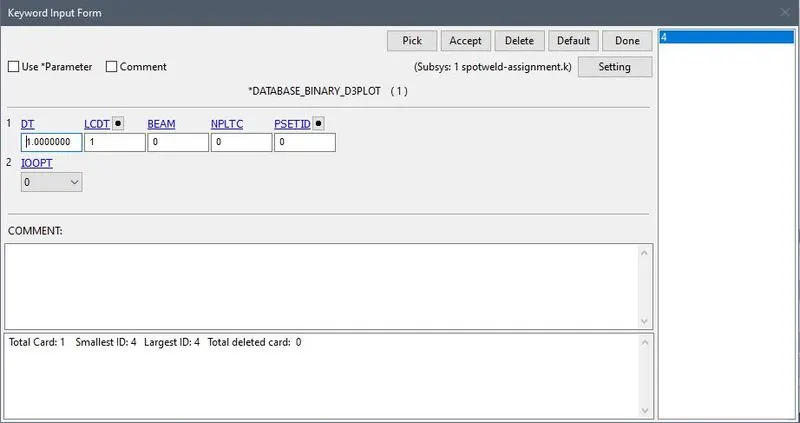
- For animated file MODEL>KEYWRD>DATABASE>D3PLOT
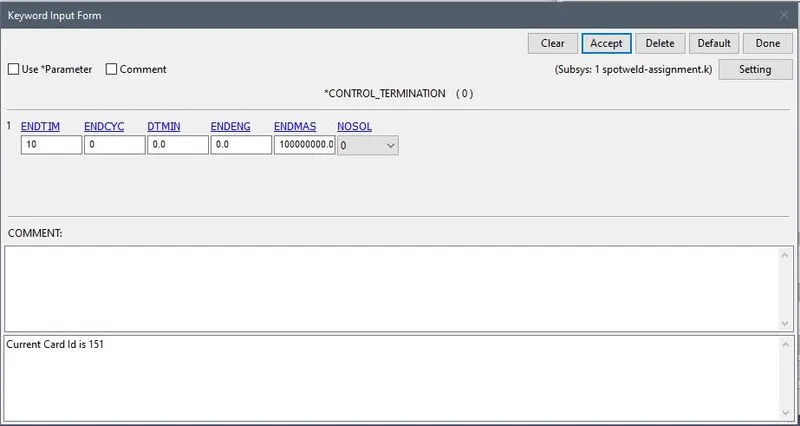
- Now for termination go to MODEL>KEYWRD>CONTROL>TERMINATION
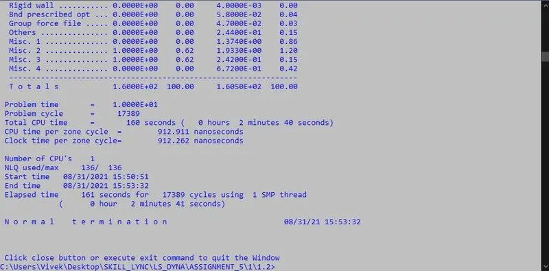
- Now we will save the .k file and check for the simulation.
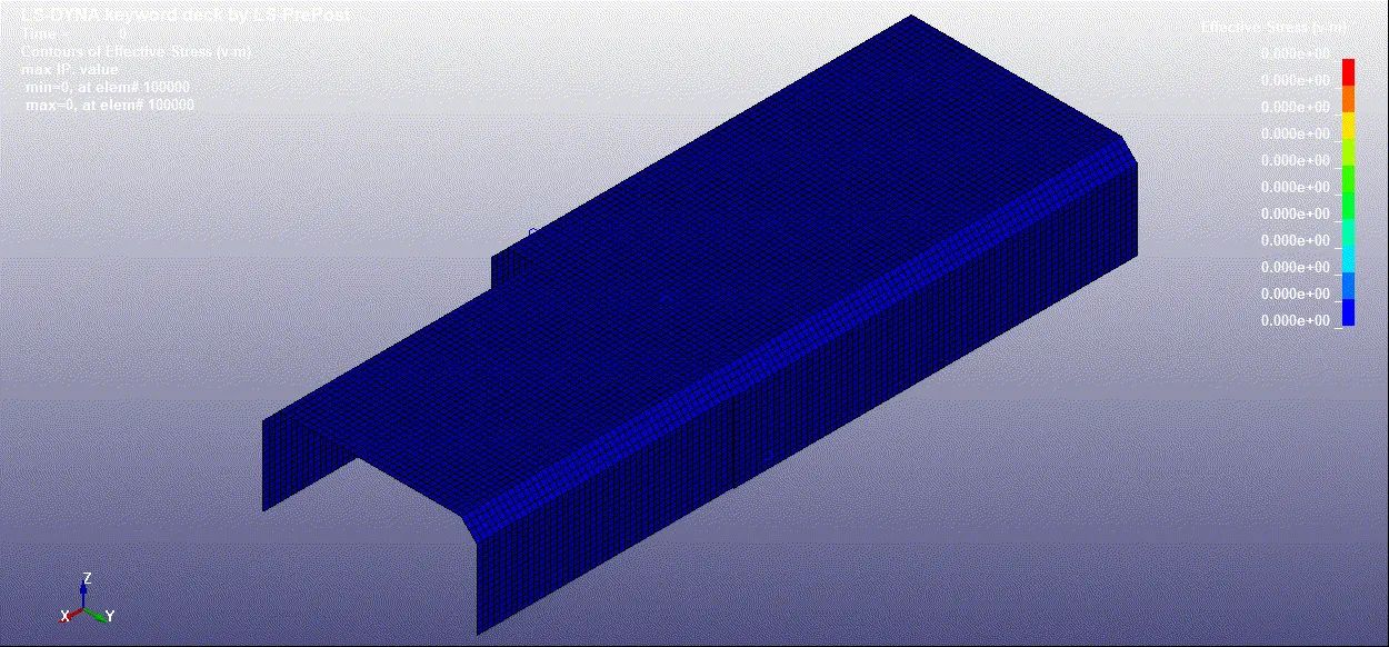
D3PLOT
OUTPUT GRAPHS:
1. AXIAL FORCE
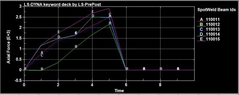
- Minimum axial force is of spotweld 110012 i.e. 2.1e+03N at 5.8ms
- Maximum axial force is of spotweld 110015 i.e. 2.9e+03N at 5.8ms.
2.SHEAR FORCE
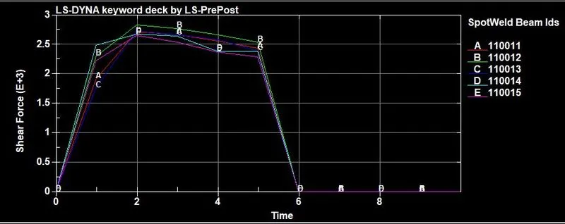
- Minimum shear force is of spotweld 110015 i.e. 2.66e+03N at 2ms
- Maximum shear force is of spotweld 110012 i.e 2.86e+03N at 2ms
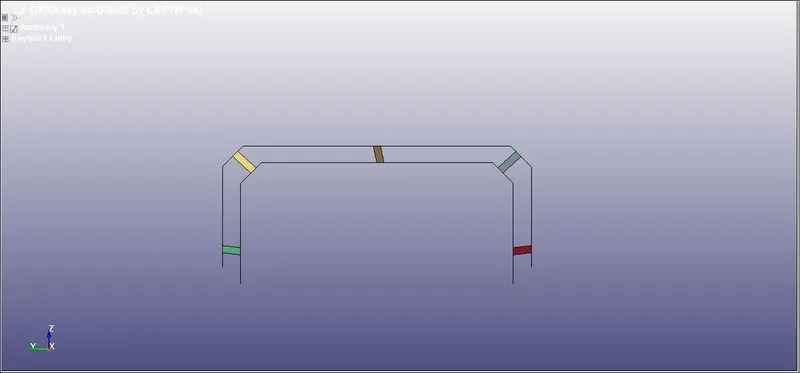
NOW WE WILL CREATE SOLID SPOTWELD
- Now to create Solid type of spotweld go to ELEMENT TOOL>ELEMENT EDIT>CREATE>ELEMENT TYPE>HEXA
- We wll create 5 spotwelds here.
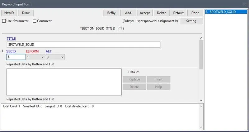
- Now we have to create section for the this SOLID ELEMENT
- For that go to MODEL>KEYWRD>SECTION>SOLID and ELFORM=1.
- Now we will apply the SECTION and MATERIAL ID to the SOLID PART
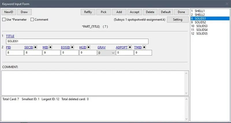
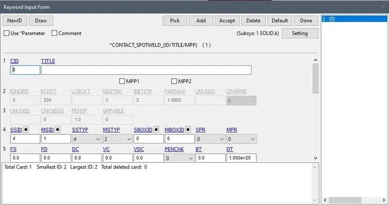
- Now after creating the PARTID we will give the CONTACT to the shell and spotsweld
- MODEL>KEYWRD>CONTACT>SPOTWELD
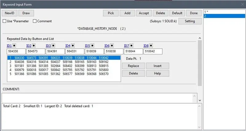
- Now we will assign the nodes of the SPOTWELD to the DATABASE>HISTORY_NODE for the output.
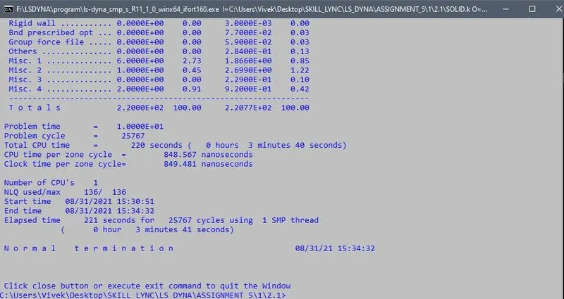
- Now we will go run the .k file for the simulation.
D3PLOT
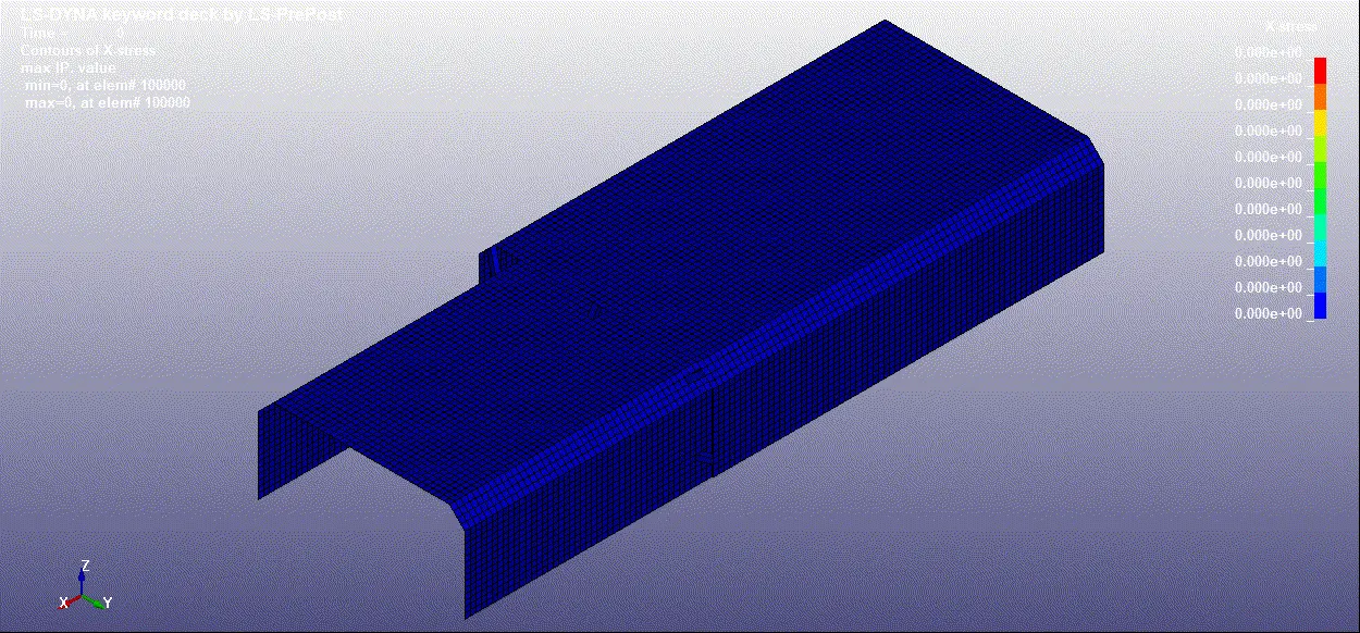
GRAPHS
1. AXIAL FORCE
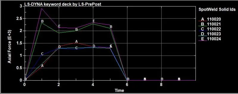
- Minimum axial force is of spotweld 110020 i.e. 0.5e+03N at 1ms
- Maximum axial force is of spotweld 110024 i.e. 2.9e+03N at 1ms.
2.SHEAR FORCE
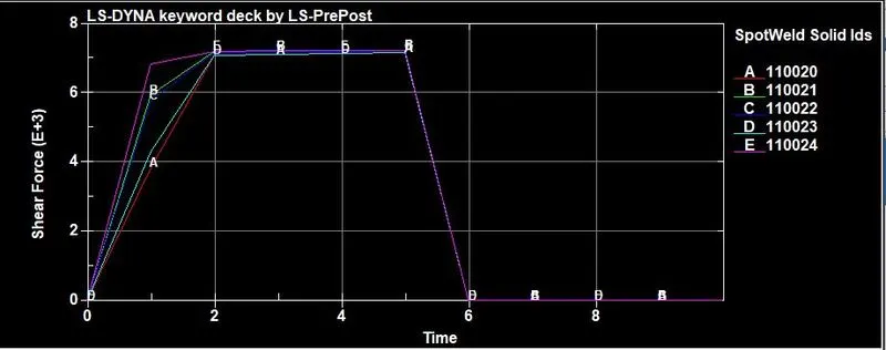
- Minimum shear force is of spotweld 110020 i.e. 4e+03N at 1ms
- Maximum shear force is of all spotweld is 7e+03N at 5ms
OUTCOMES:
- Got knowledge about the different types of spotwelds.
- Able to create the BEAND and SOLID type of SPOTWELDS.
- Got knowledge about SWFORCE and NODOUT
RESULTS
- Beam and Solid type of Spotwelds are created at different area of the Shell elements.
- Property are assign to the both type of SpotWelds.
- Required graphs are plotted.