Week 6 - Creating connection for Rear door
Aim: To create the connection for Rear door of car.
Procedure:
- The rear door is as shown below. The connection of Rear door is little bit complicated as compare to front door.
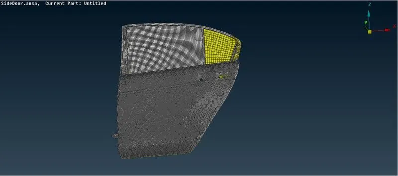
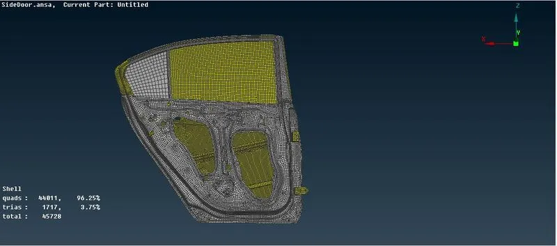
- Now as we have to do the connection on the door, it is done in NASTRAN module. As it is use for NVH,
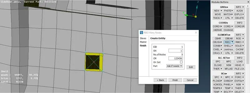
- As performing the connection always keep in mind to give the degree of freedom (DoF) to the joint. It may vary at every connection the CM in this photo represent the DoF of the that perticular connection so change it accordingly.For bolt all the degree of freedom are restricted so we using all the restrictions 123456 And after that your connection is done for the perticular hole. Now to connect them you have to perform the operation on both holes.
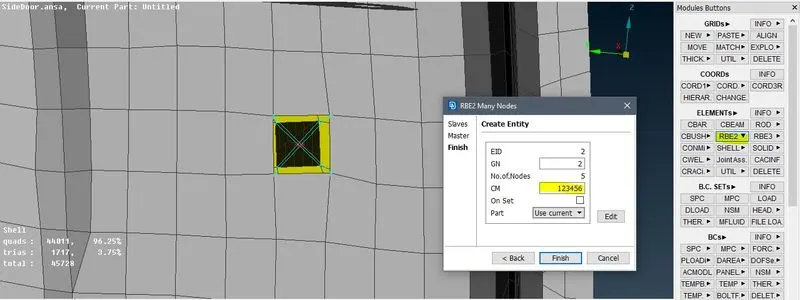
- Now to join the connection to each other we have to perform different operation called two nodes its Elements> RBE2> two nodes. Then select the nodes which are formed at he center of the holes and perform the operation, the yellow line represent that both are connected to each other, as shown below:
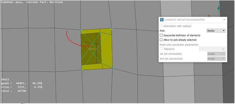
- Now we will perform the RBE2 cluster connection the procees for this connection is same as the above but this time we done required two nodes option, Just simply perform Elements> RBE2> Many nodes an select the node on all the hole which are near to each other and retrict the DoF. Its as shown in below images:
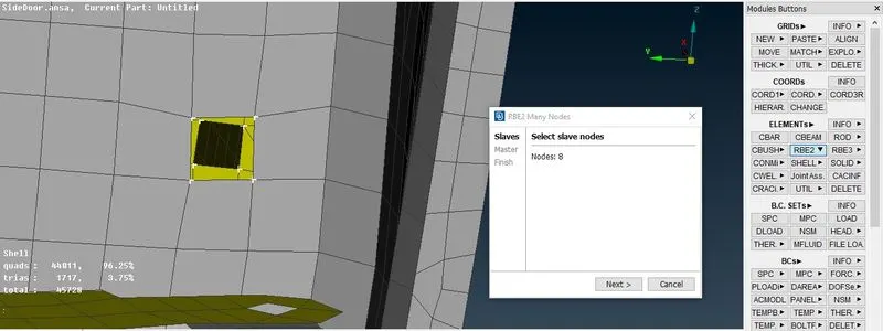
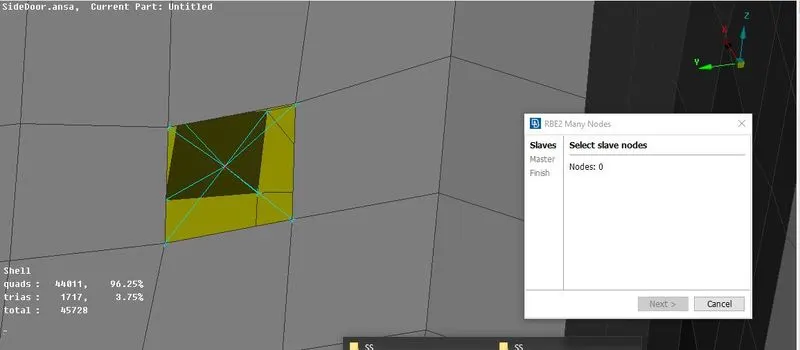
- Now we will perform autoconnection it is know as Bolt connection for that we have to create the COG from TOP>POINTS>COG on any of the hole after that convert that COG into bolt with the help of CONVERT option at Assembly module.After that perform CONNCTION operation from the Assembly module as well.
- Now selcet 3D points from convert and then select the CoG which we created and then convert that COG into Bolt.
To create the bolt connection we have to select the all part which we have to connect and then peform the final operation as shown below:
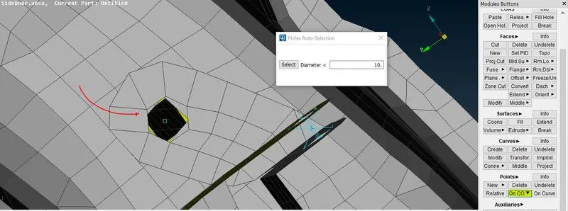
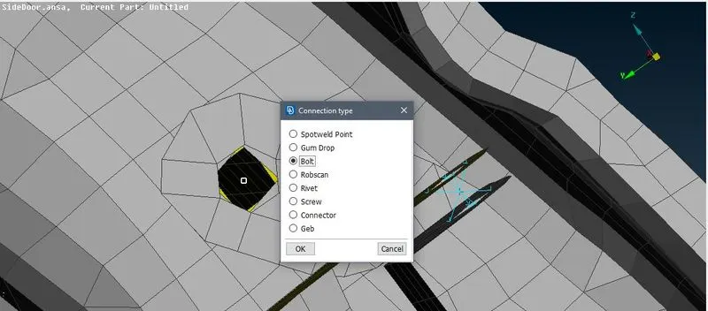
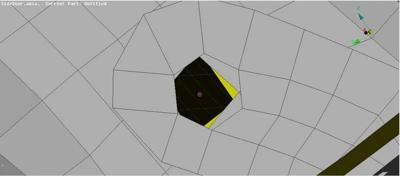
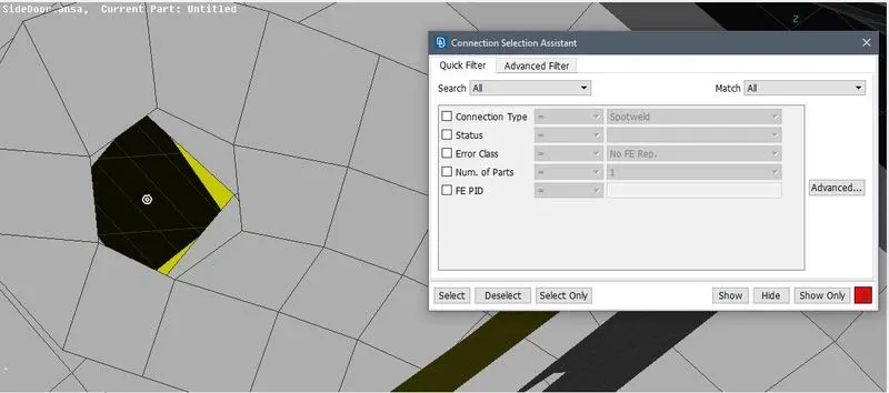
- Now the bolt is created we have to perform the connection so for that select the connection and select the bolt and then we have to select the part near to it to select the part right click on P1 then modify and press FUNCTION F1 key so select the part ,then select the bolt option and assign the other value in he give tab as shown below:
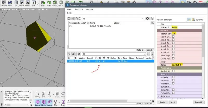
- So this is how we assign the value to the connection and perform the operation. The connection will look like as shown:
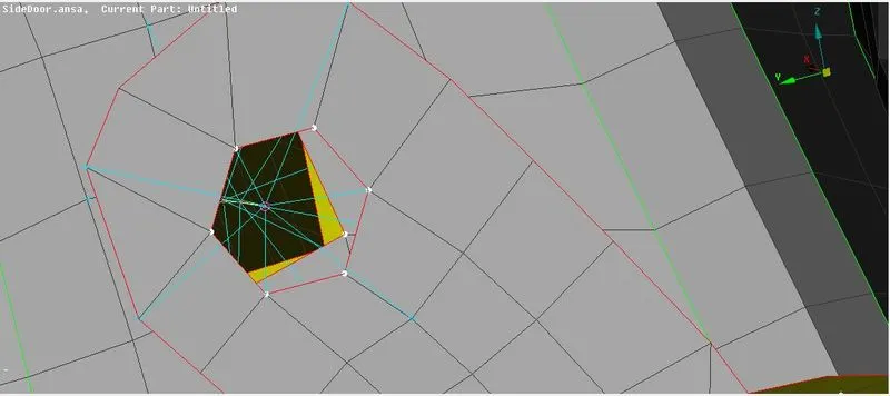
- Now we will perform the connection to the handle its RBE2 connection for that we select the two holes provided for the door handle and then performing the spider connection on it and then connecting those two connectoion to form a centroid of the connection as shown below:
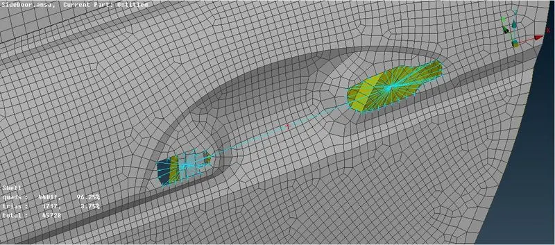
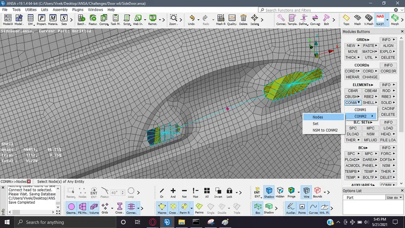
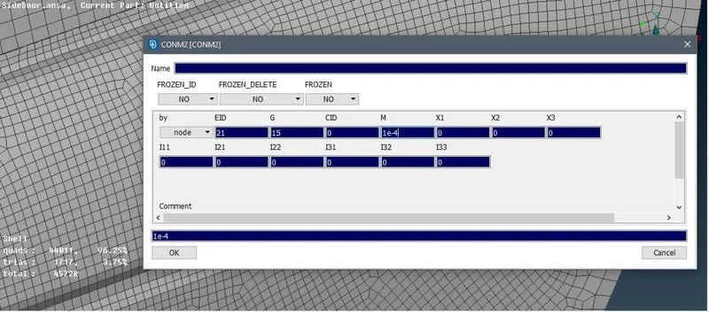
- Now the connection is done we have to provide the Con Mass on the Cetroid point for that we have to use NASTRAN module then Elements>CONMi>CONM2>Nodes after that select the cetroid point and assign the mass to it. The mass value is assign in tonnes so 100gm= 1e-4 tonnes it is as shown below:
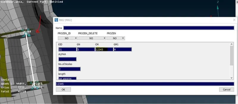
- Now we have to give connection to the door hinges for that the process is same but the change is in the DoF of the hinges so for that give connection to hinges and then select Elements>Info and select the two nodes connection then change the CM to 12345 this means the we are assiging only the rotation motion in Z direction and others are restricted it is as shown below:
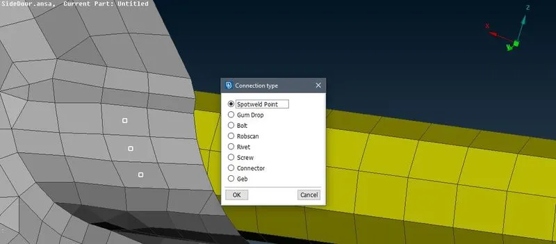
- Now we have to perform the Spot welding Connection. For this we are going to spot weld where the spot weld connection is required. For that we will create the COG on the required area and then convert those COG points into spot weld using CONVERT option in Assembly. It is shown below:
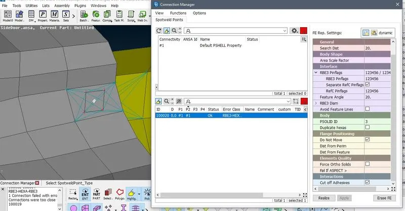
- After that go to connection manager and select the all the spotweld points. Then the connection tab will open after that give the connection to the part usig F1 tab. Then the select the FE representation as RBE3-HEXA-RBE3 and then assign the values, make sure the all the DoF are restricted.
- Using the RBE3 Pinflag option create solid spotweld connection. It is shown below:
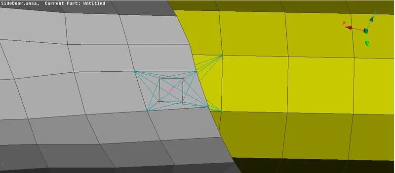
- Now for the Window Bushing Connections. In this we have to create the curve first from the window using Perimeters> Feat2Curve option in Mesh module. Then we convert those curve into spotline using the CONNECTION option, select one curve at time and apply spotline to each curve as shown below:
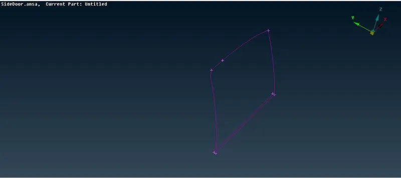
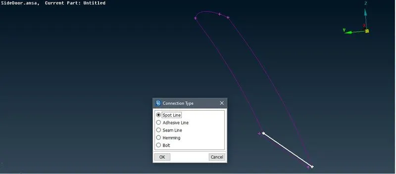
- Now we have to select the part and selecting the part the FE presentation will be RBE3-CBUSH-RBE3. In that assign the required value also select the Keep all the branches. Then Apply and Realize and the bush connection is formed as shown below:
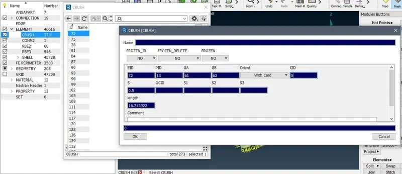
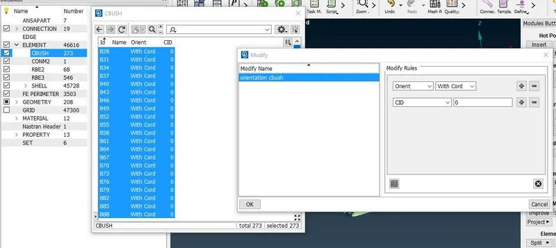
- After that we have assign same orientation to all the cbush element in same vector direction. So go to the CBUSH element and give modify and assign the coordinate as 0. So in this we all the bush are elements are aligned as same as global coordinate. It is shown below:
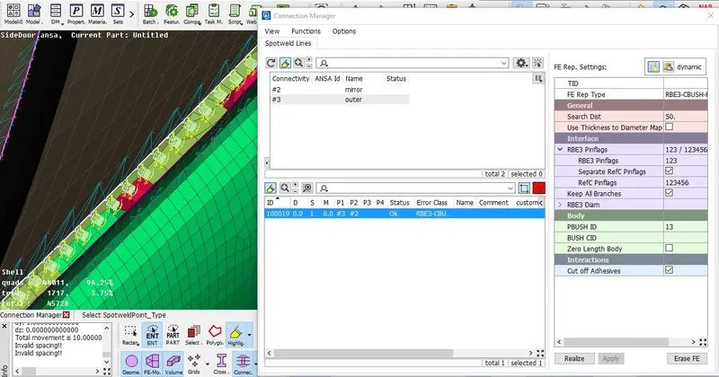
- CBUSH are formed now to orient them in same direction is shwon below:
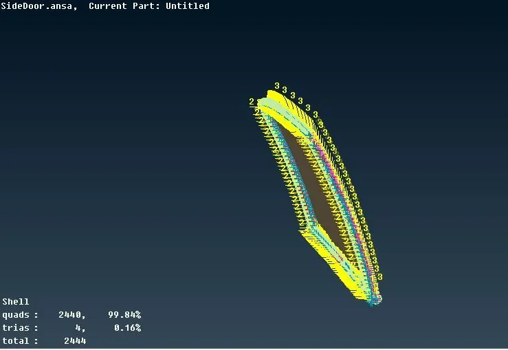
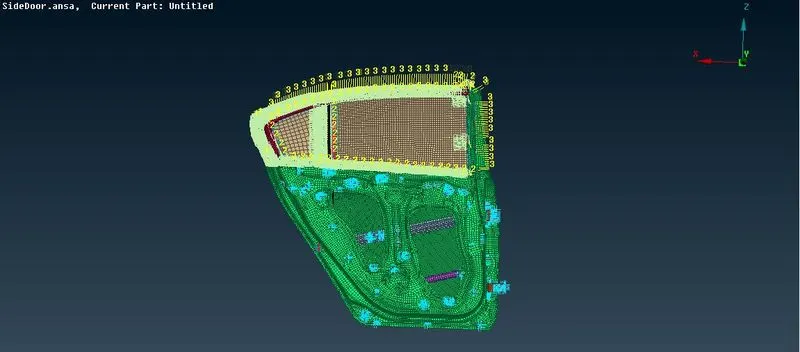
So the after completing all the connection the door will look like this as shown below:
Learning Outcomes:
- Got the knwoledge about different types of connectivity.
- Also how to assign the different Degree of Freedom to different componant according to there movements.
- Got knowledge about the different types of welding and RBE2 funtions.
Conclusion:
- The connection to all the componant is done.
- Degree of freedom are assigned to the componant accordingly.
- Welding and CBUSH connectivity are done properly.