Week 5 Challenge : Surface wrap on Automotive Assembly
1] AIM -
To perform wrap on an automotive assembly.
2] OBJECTIVE -
*Resolve geometrical errors for all 3 moddels and delete surfaces which are unwanted for the surface wrap.
*Merge all 3 models and perform surface wrap.
*Write a detailed report.
3] INTRODUCTION -
ANSA is a computer-aided engineering tool for Finite Element Analysis and CFD analysis widely used in the automotive industry .It carries several proprietary algorithms for meshing suitable for both CFD and structural models.
Surface wraping is used for meshing the componentsfrom outside.If we wrap any component then we can only see outside. We are only concerned with the outside of the model and don't care about inside components.Our task is to remove unnecessary surfaces from the models and patch our surfaces ,so not to have any holes.Surfaace wrap is used for external analysis.
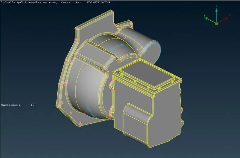
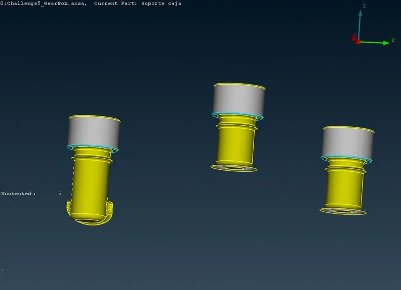
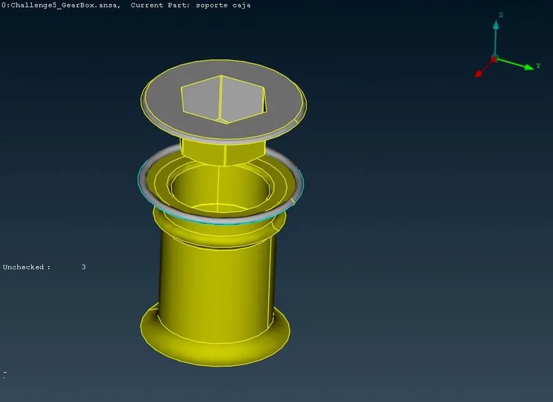
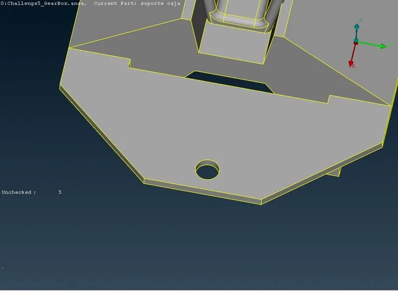
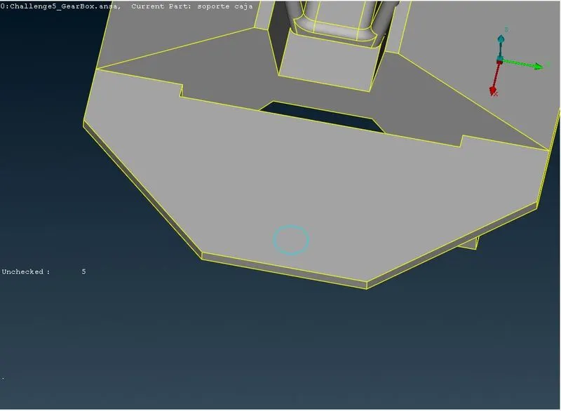
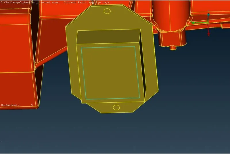
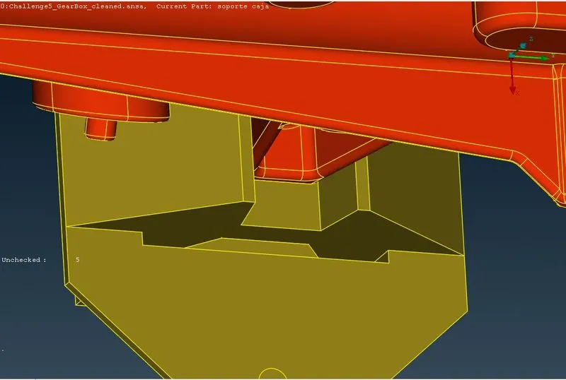
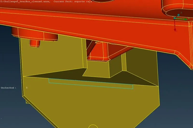
We have been provided with a CAD modesl of engine,transmission and gearbox, with some geometrical errors.As from the model we can see there are many openings in the models which we need to close before wraping.We can also see unchecked surfaces,which are nothing but the surfaces smaller than perticular mesh length or any minimum width surfaces.Surface wrap should capture the perticular component exact,otherwise the CFD analysis which we are interested in won't work properly.
4] PROCEDURE -
4.1] Topology Cleanup -
4.1.1] Engine-
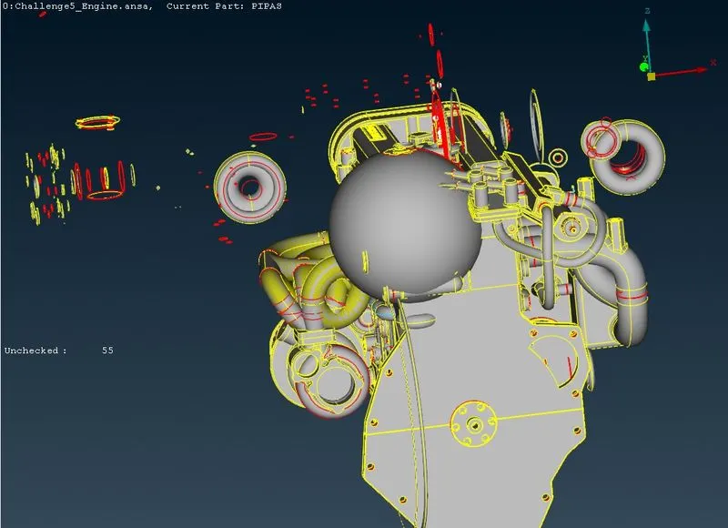
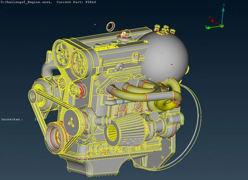
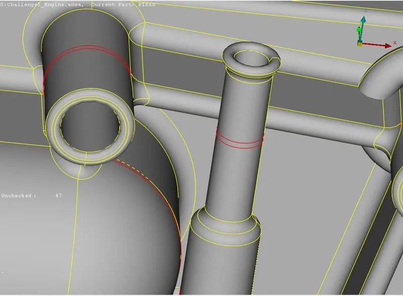
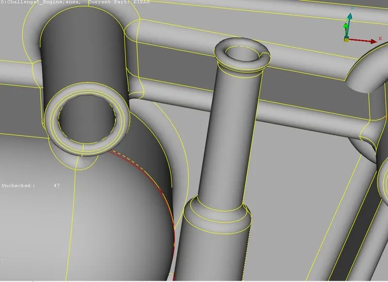
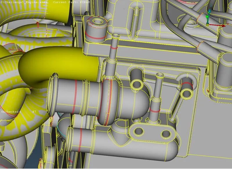
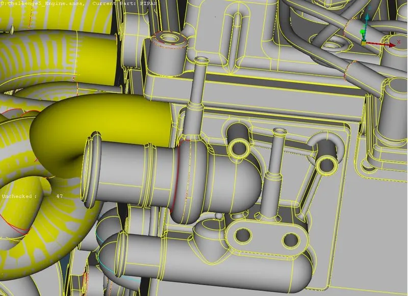
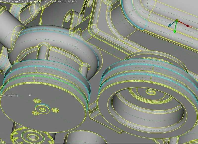
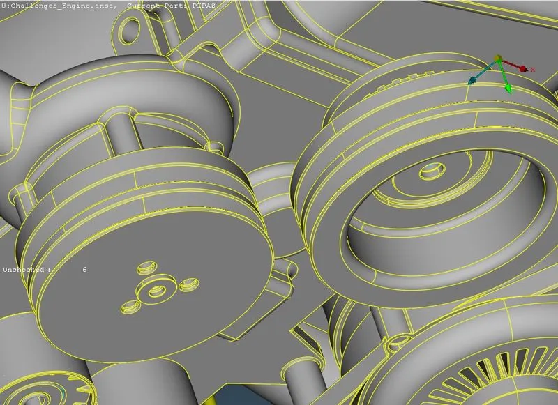
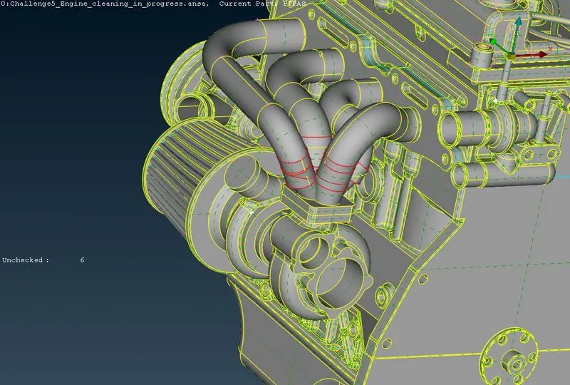
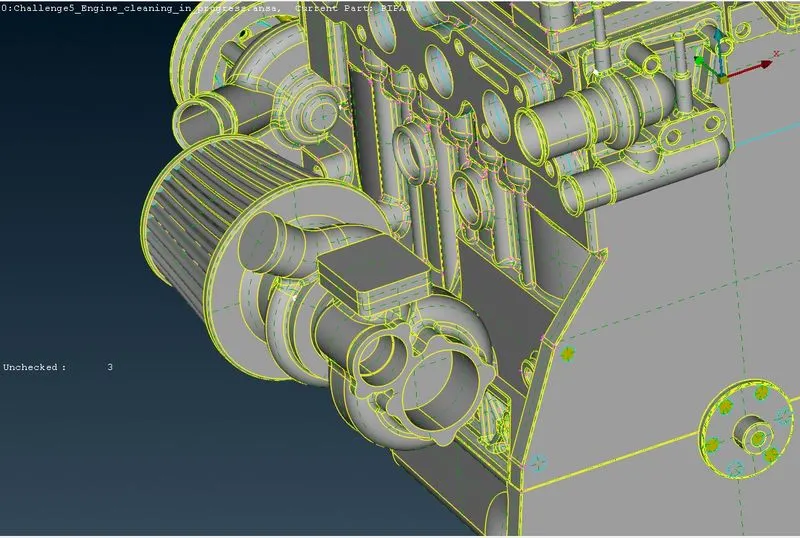
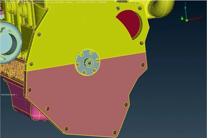
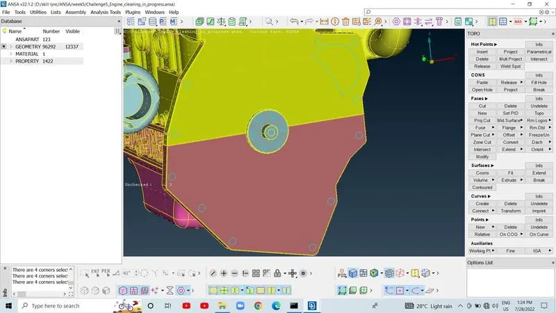
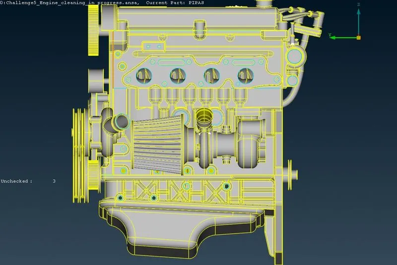
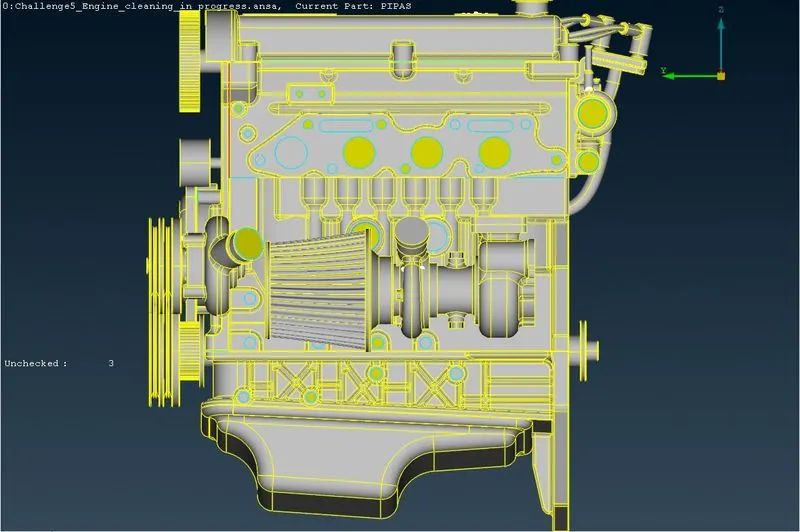
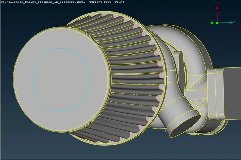
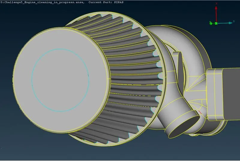
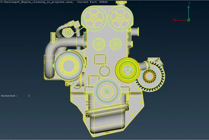
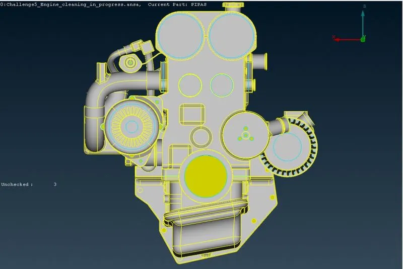
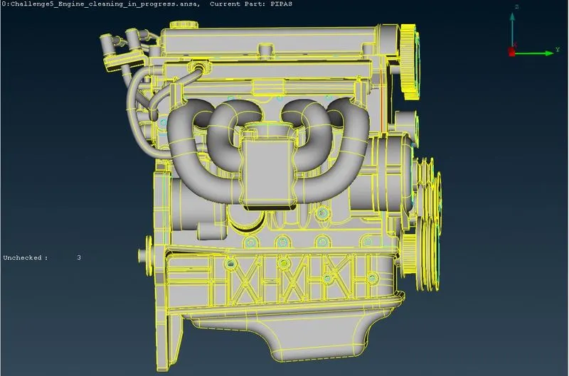
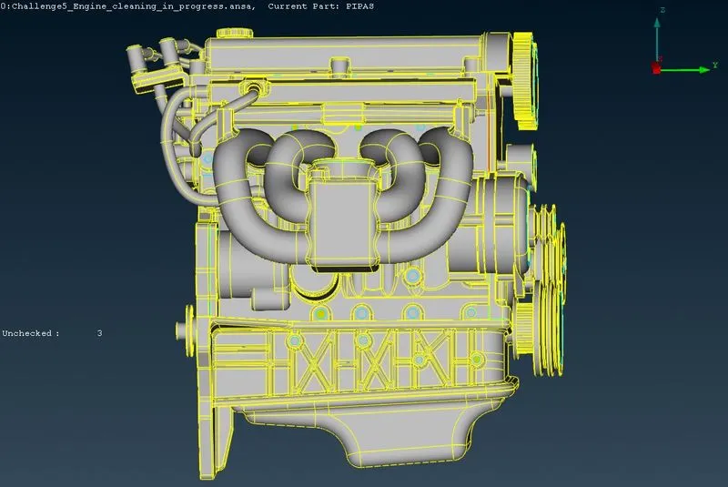
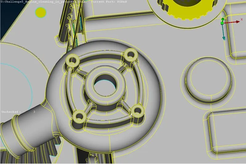
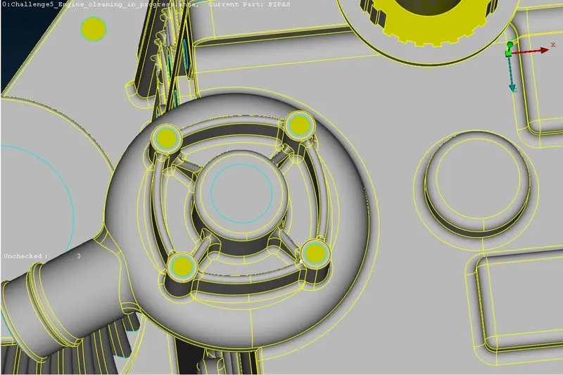
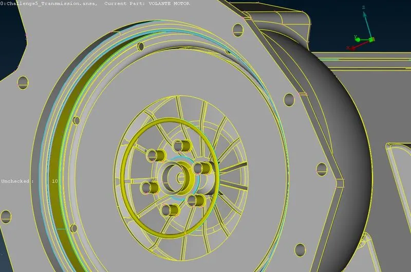
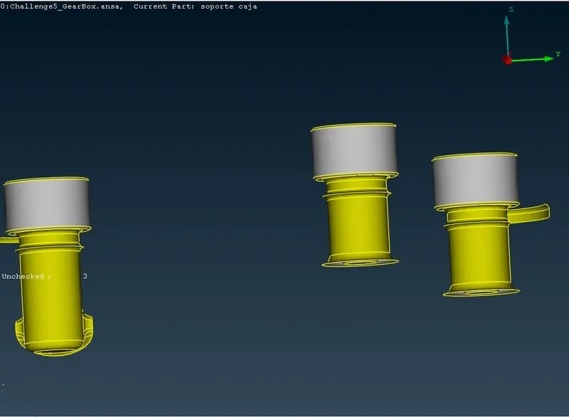
We can see that there are many ring components which have no use in the model ,thus we will delete them using universal delete option.We will isolate these rings from the main model using NOT tool and then delete them.We need to be sure that we are deleting unwanted surfaces and not the wanted one.We will remove belts .They are very thin and thin parts won't get captured properly in wrap.
4.1.2] Transmission -
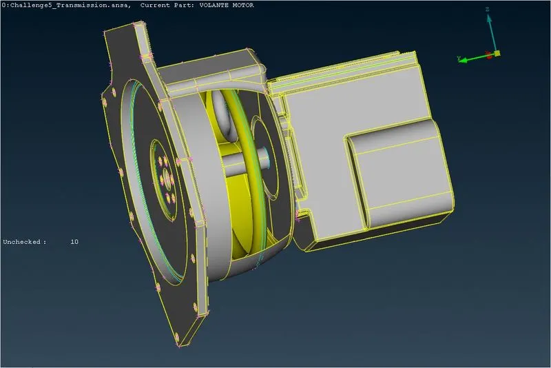
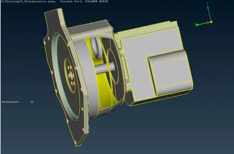
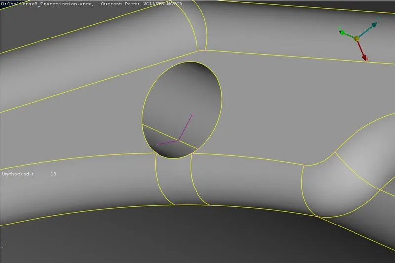
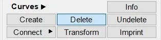
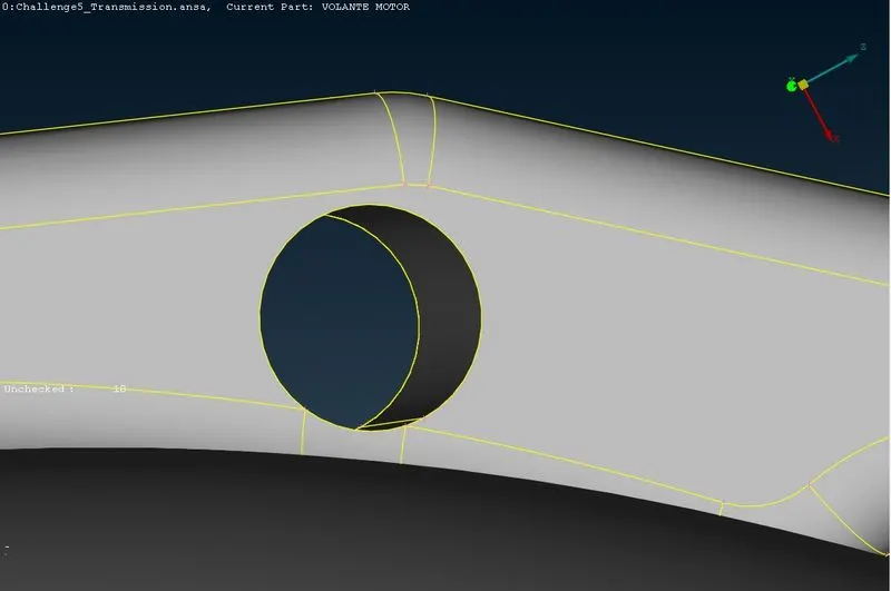
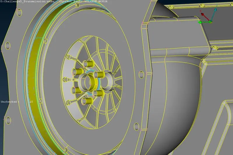
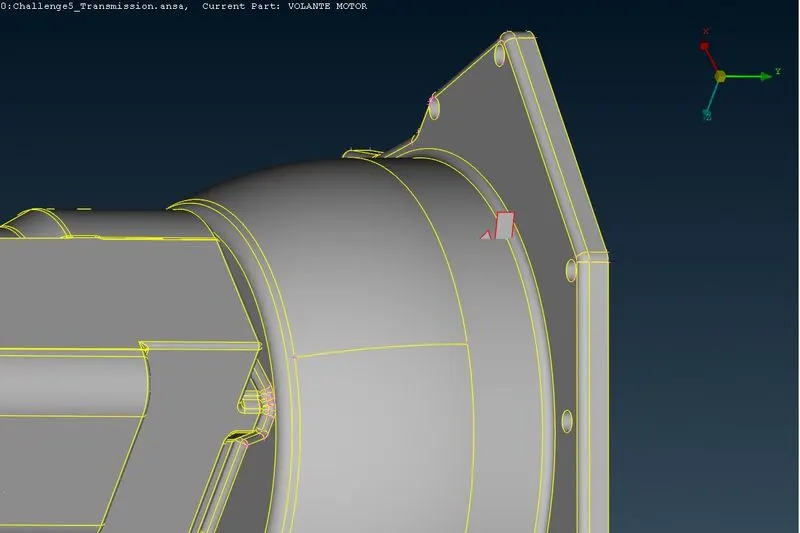
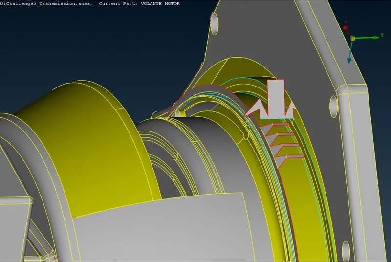
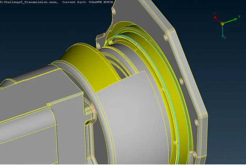
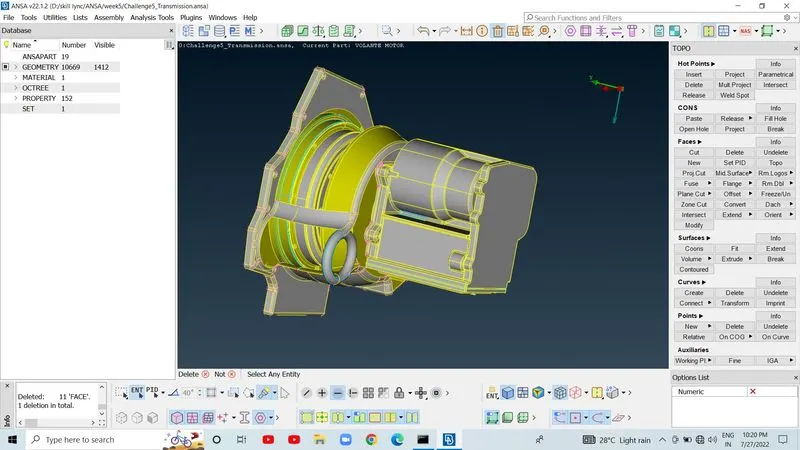
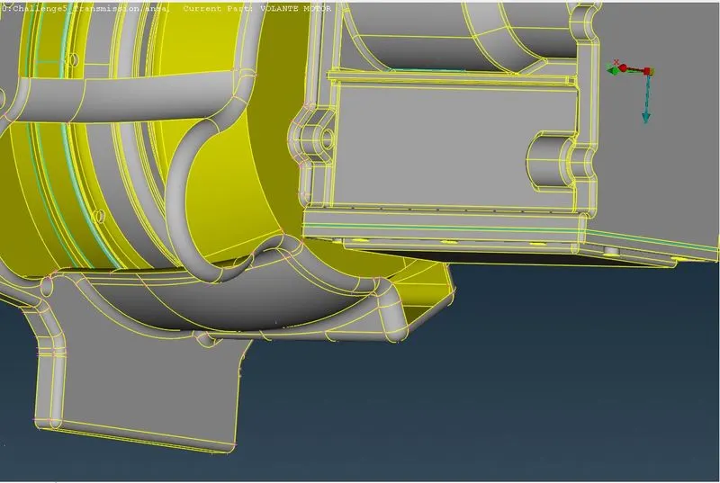
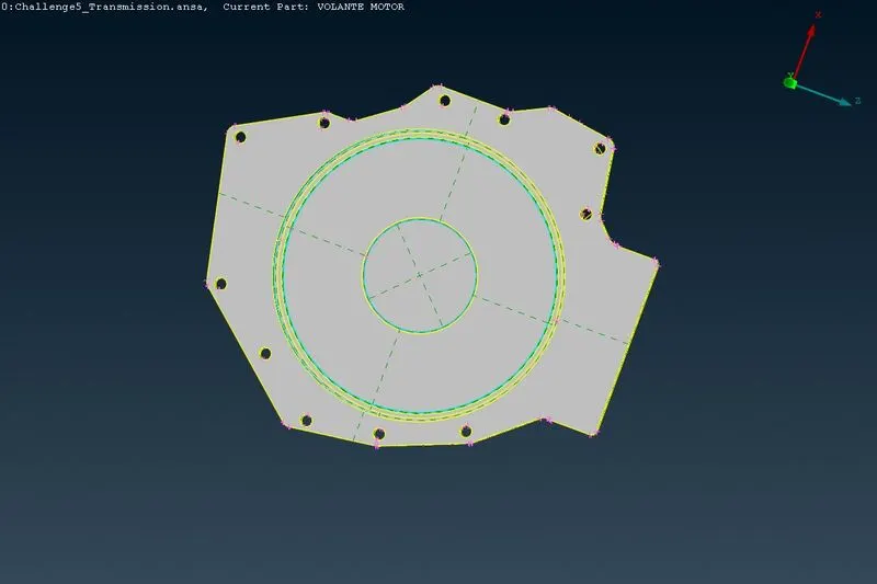
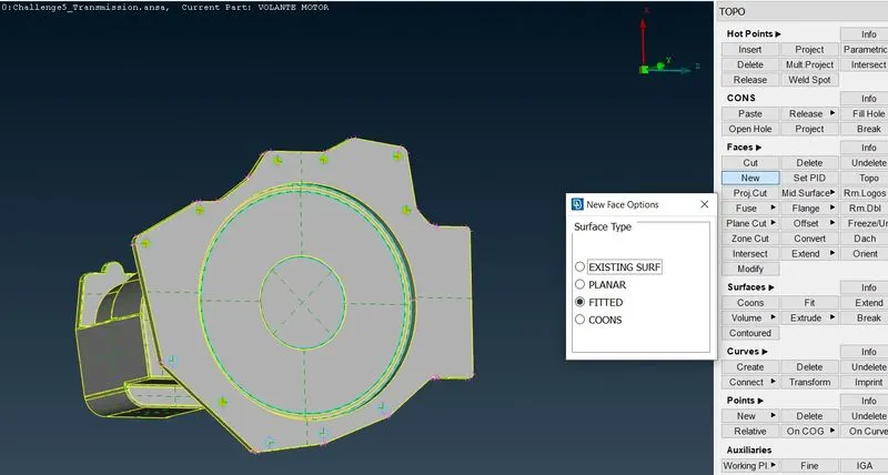
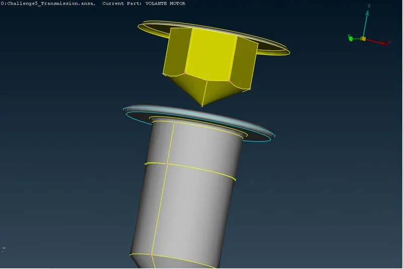
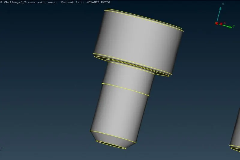
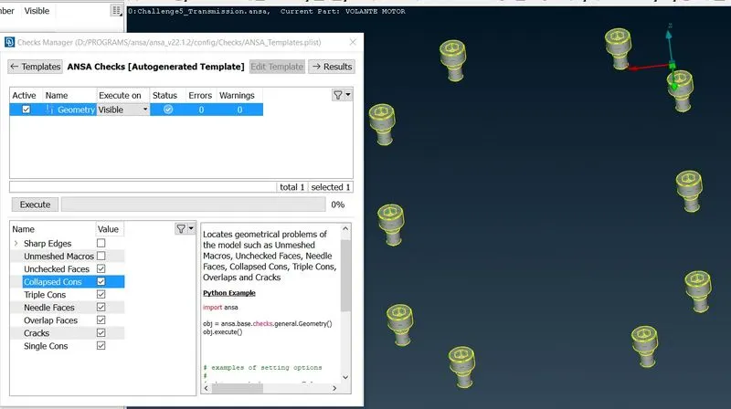
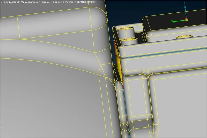
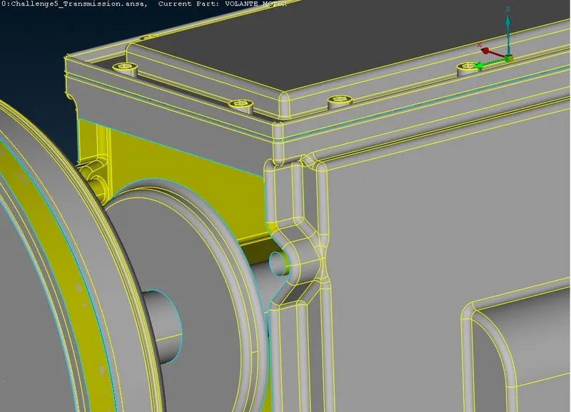
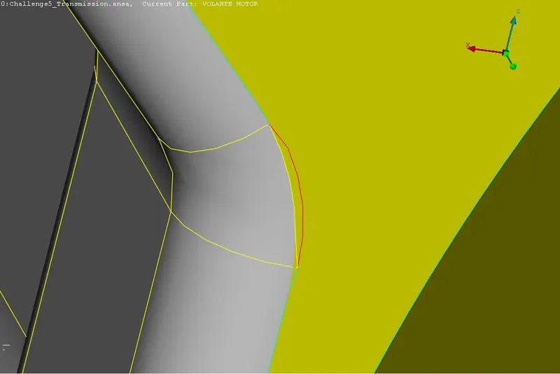
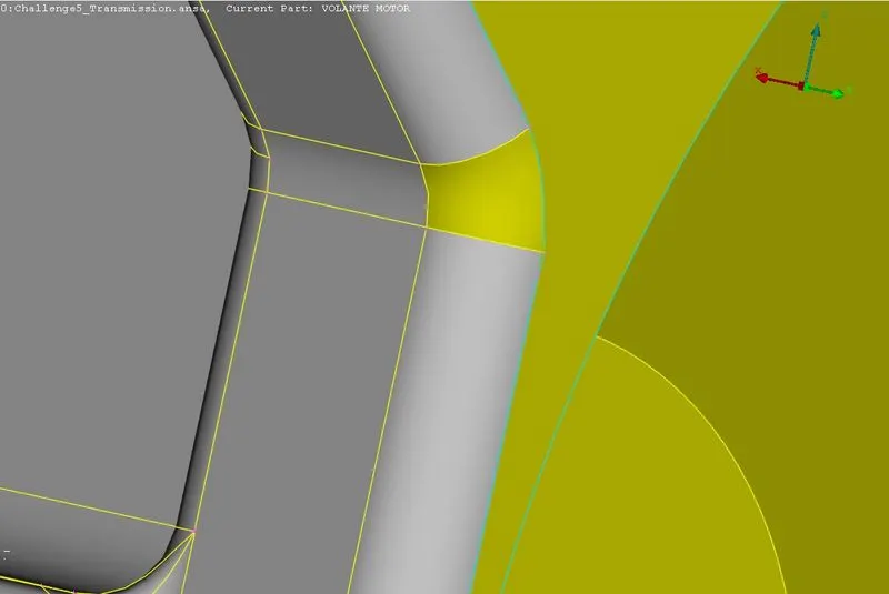
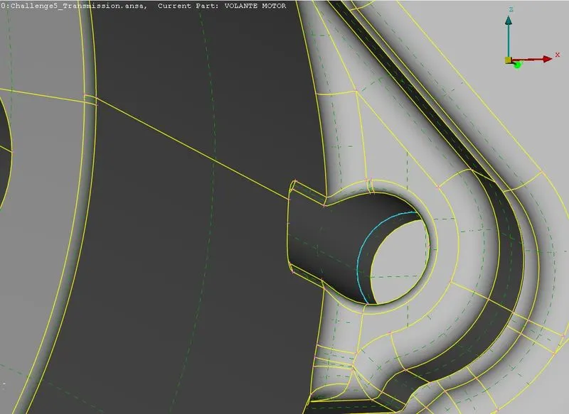
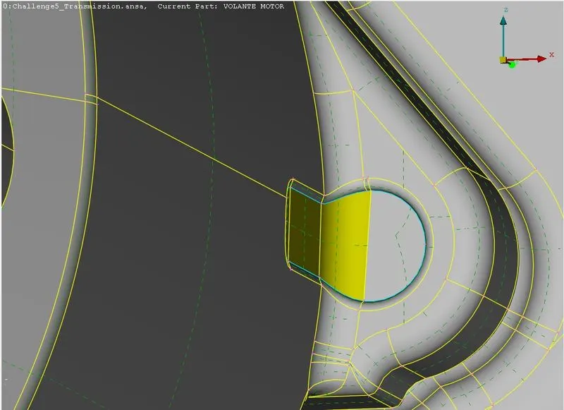
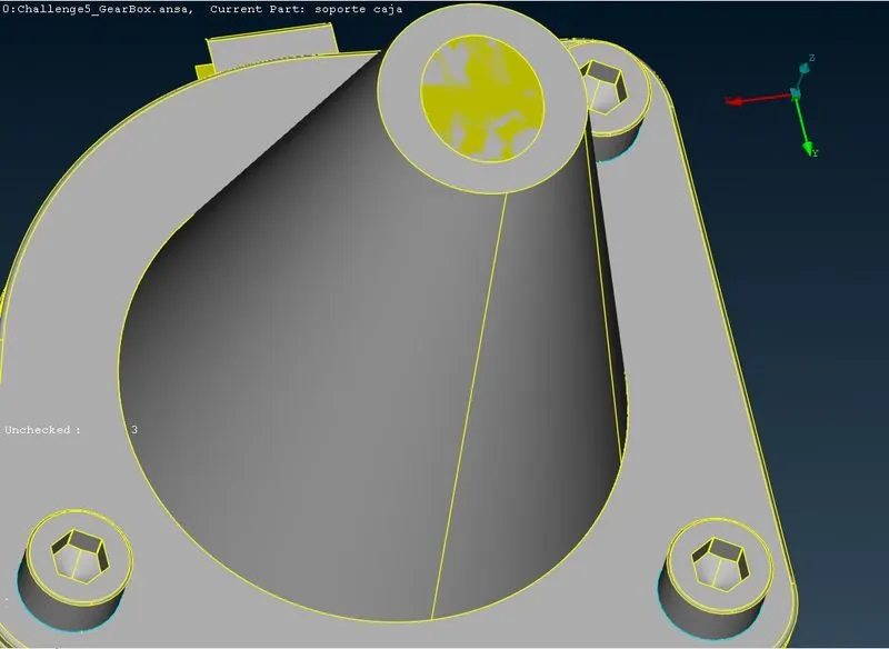
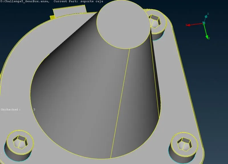
For surface wrap we ahould not have any holes present,otherwise wrap won't work properly.By doing surface wrap,we will be ensuring that we have a closed volume in which we can do volumetric mesh in the later stage for CFD studies.
4.1.3] Gearbox -
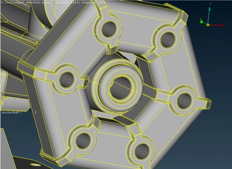
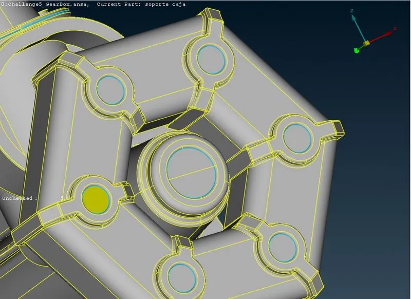
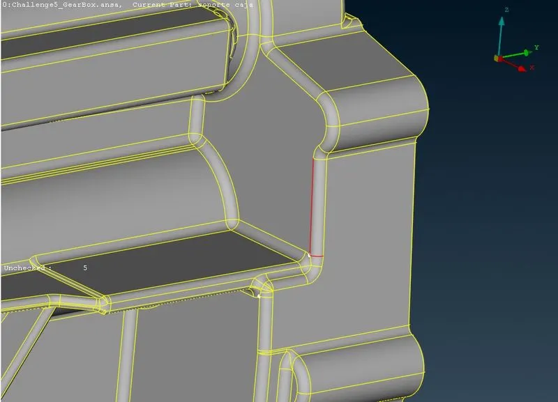
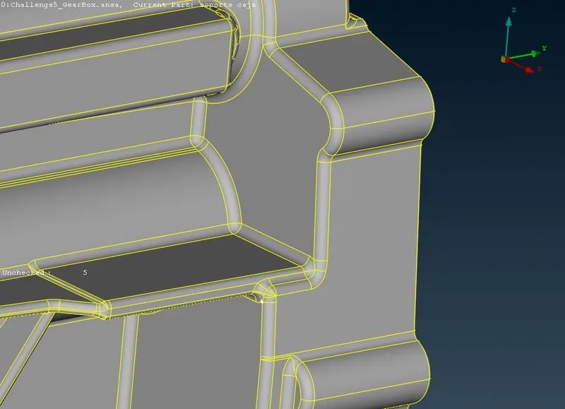
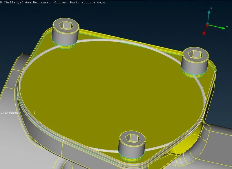
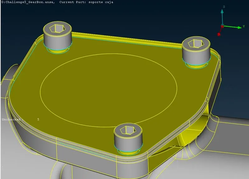
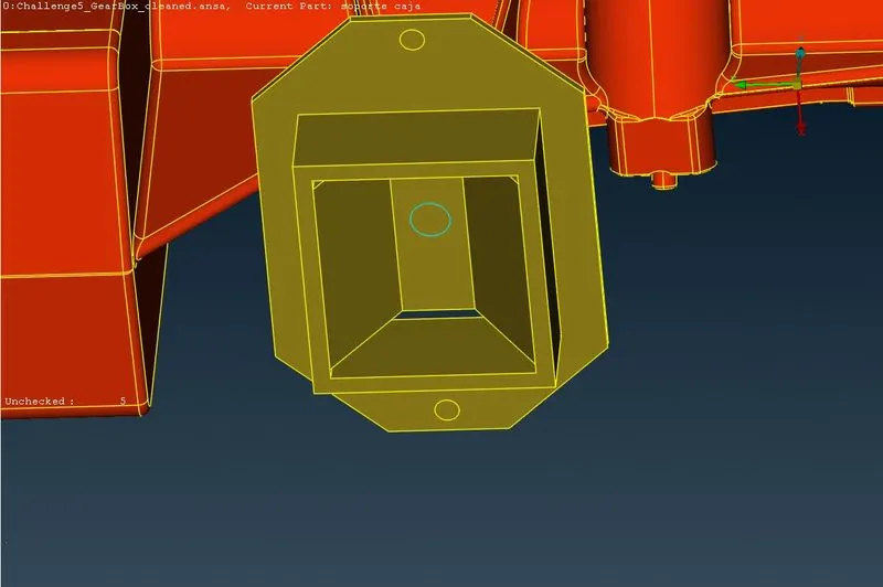
Simillarly we will patch any holes present in the gearbox model.
4.2] Merging of all 3 models -
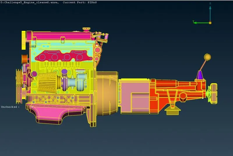
Now we want all 3 models inside the same working window.Thus will merge them together.To merge all models follow the below steps,
Go to File => click on Merge => Select the desired file => click on Open => enable merge parts => in model action select merge model with current model => ok.
This will merge new model with the existing model.
4.3] Surface Wrap -
Here we will deploy surface mesh which is water tight i.e.there won't be any gaps over the surface i.e. closed surface or a closed volume.In this case we will surface wrap so that it can form common volume for whatever inside surface wrap instead different volume.Since surface wrap uses PID's,first we will compress unused PID's using compress tool.Thus select arrow symbol beside the measure tool and select compress then press ok.This will delete the unnessary PIDs.
To do surface wrap follow below steps -
Go to Mesh deck => select Wrap.
In wrap there are two options constant length and variable length.Constant length take only one target length,constant throughout the assembly.And variable length takes variable mesh length for surface wrap.We will use constant length.
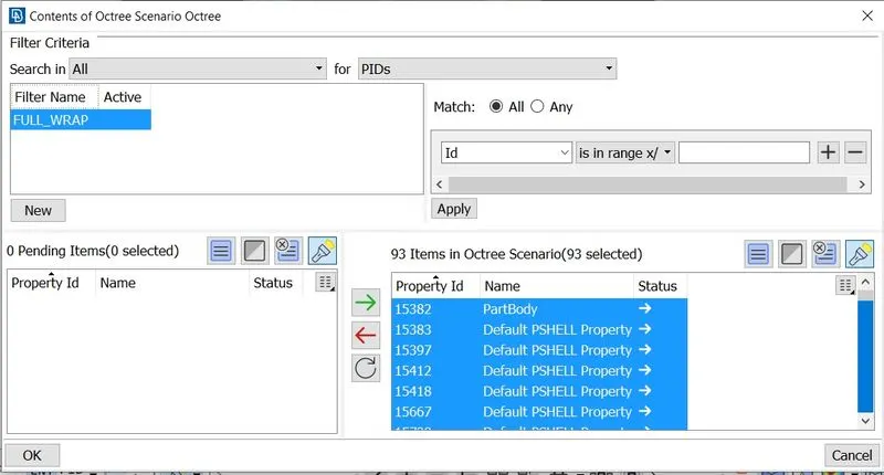
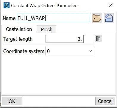
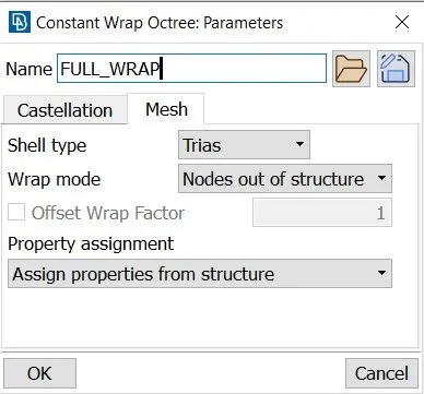
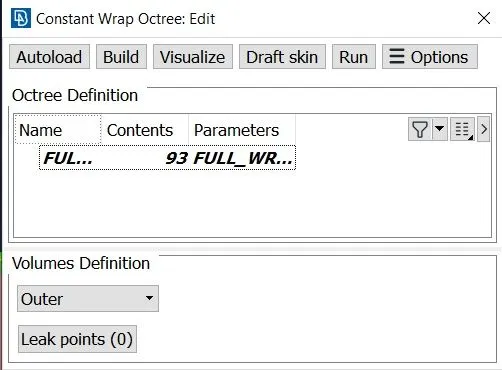
In Constant lenght => Double click on empty => In parameters give name as FULL WRAP => set taget length 3 mm => in mesh tab select Node out of structure and select assign properties from structure => ok
Now double click on contents => enter filter name as FULL_WRAP => at the bottom select all the PID's which we want to wrap => then click on green arrow => ok => Click on RUN.
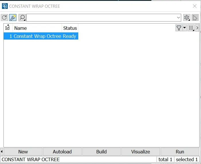
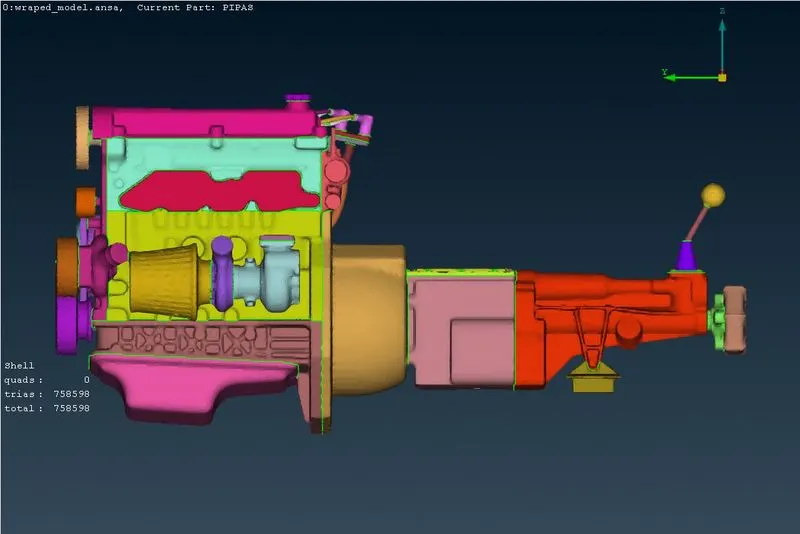
We can see status showing ready ,i.e. surface wrap is finished.If we are not closing holes our surface wrap will go inside perticular volume and we will loose geometric accuracy i.e. we may get distortions.Thus we must close holes to prevent these kind of distortions.We can see each element is taking PID of their parent geometry.
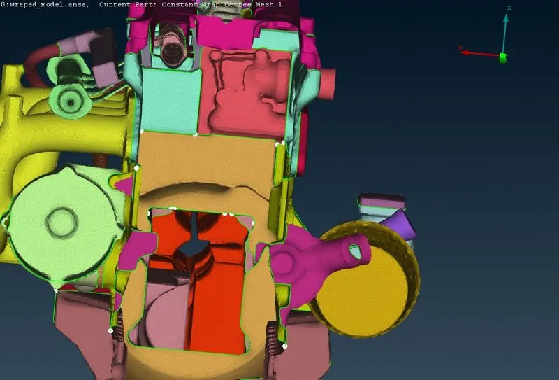
To see only click on Geometry tab at the bottom left side and FE-Mode tab to see wrap only.As we hide our surfaces using NOT tool we can see we have common volume.As we hide front and back most surfaces,we are able to see throughout the model , that means we have captured our volume very correctly.
5] RESULTS AND OUTCOMES -
*From the above images we can see that,desired volume got captured accurately.There isn't any mesh penetration inside the CAD models.
*Small mesh length results in longer time for surface wraping and while larger length results in small time.
*Simillarly small target length results in better surface capturing and vice versa.
*It is necessary to patch all the openings or holes in the geometry in order to capture outside details and to prevent mesh leaking inside the geometry.
6] CONCLUSION -
* We have successfully performed topology cleanup on the given engine,transmission and gearbox models and removed all unwanted surfaces.
*Successfully generated surface wrap,which can be uased for volumetric mesh.
*Also learned what is surface wrap and how to performe surface wrap.
*Thus we have successfully generated surface wrap for all 3 models.