Week 5 Challenge
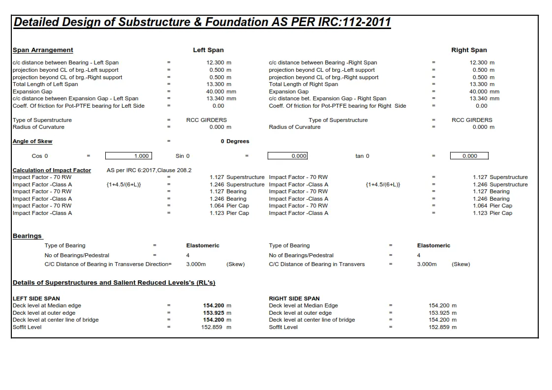
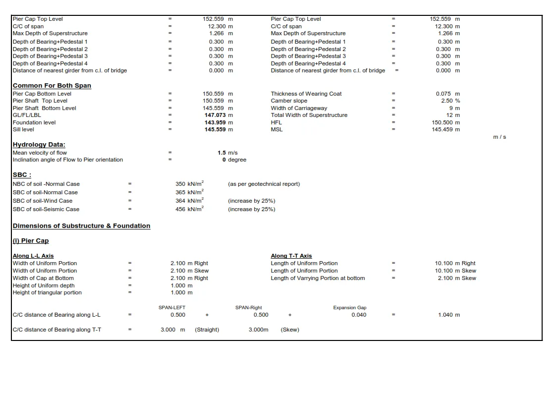
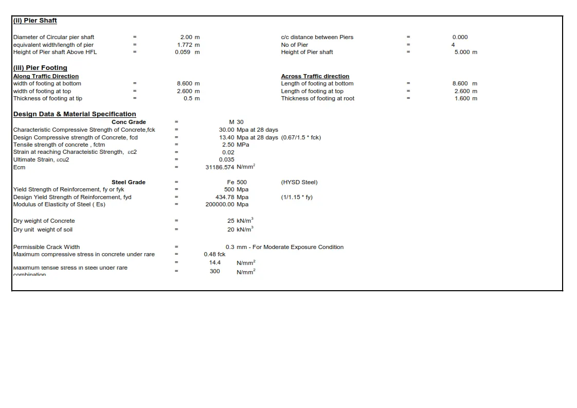
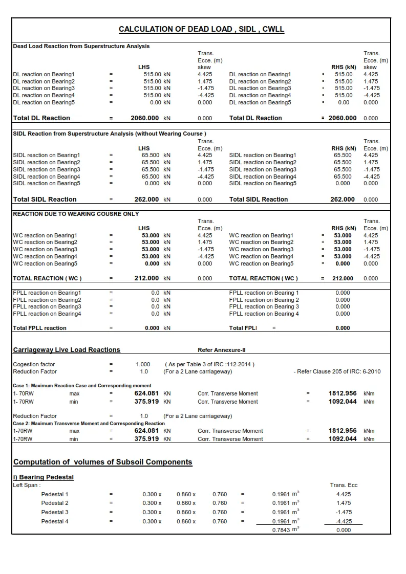
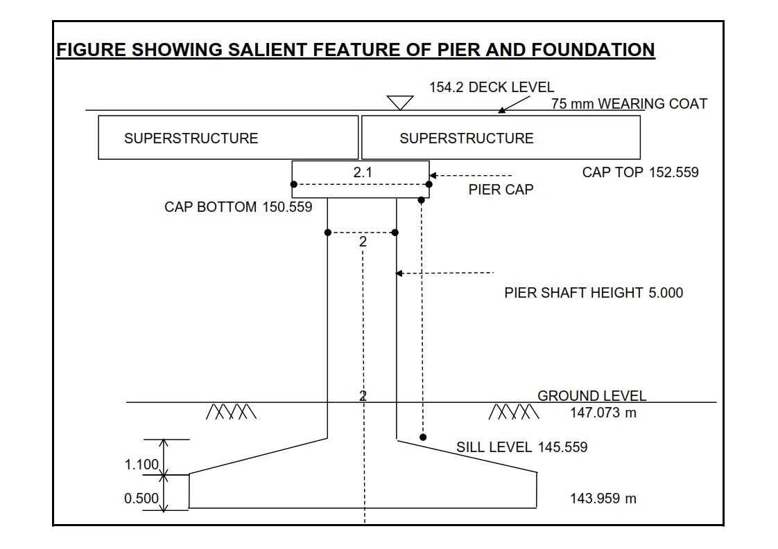
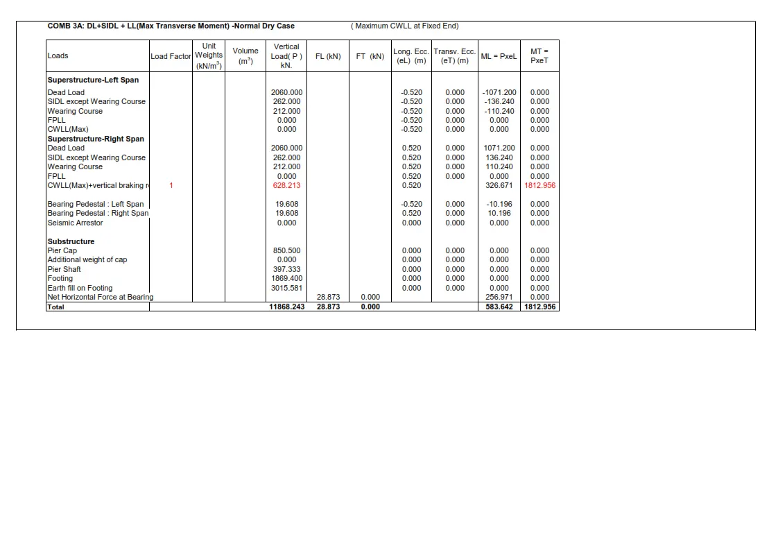
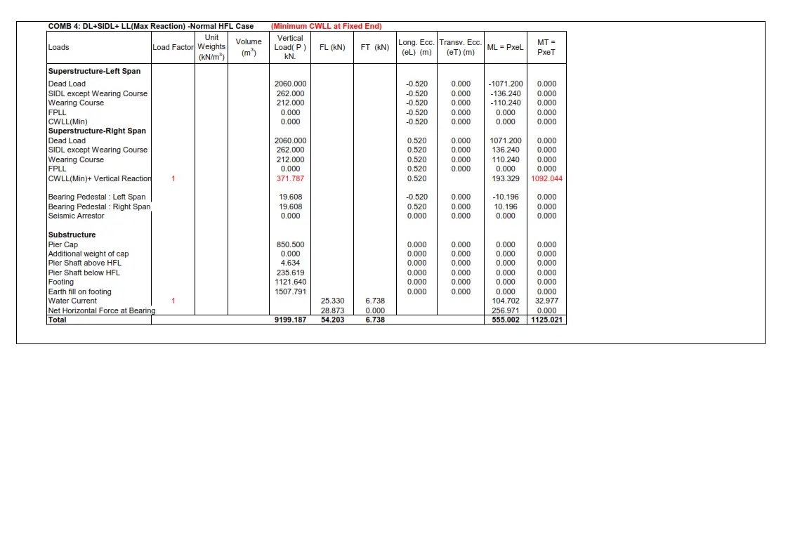
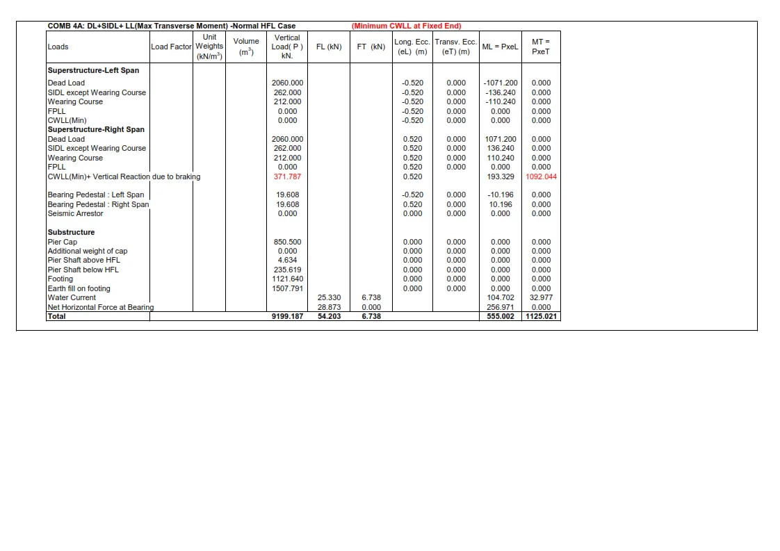
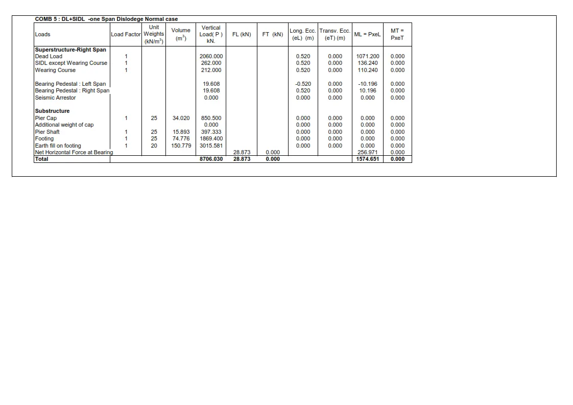
Answer 1 - As The Given Figure Doesn't have following Points So We have to asssume Accordingly :
Assumptions :
- Pier Shaft Height - 5.0 meter (Assumed)
- Superstructure Depth - 1.266 meter (Assumed)
- Design Discharge - 100 Cumec.
- Bed Level of Pier - 147.073 meter (Assumed)
- Formation level - 154.200 meter (Assumed)
- Soffit Level - 152.859 meter (Assumed)
- Rock Level - 145.459 meter (Assumed) (It is Assumed that 3.114m below the bed level the foundation is fixed and 1.5m below from rock level as per IRC 78.)
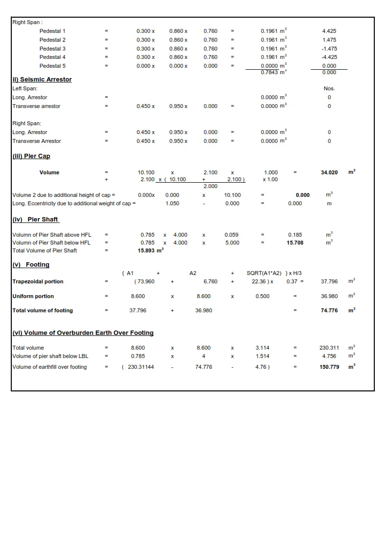
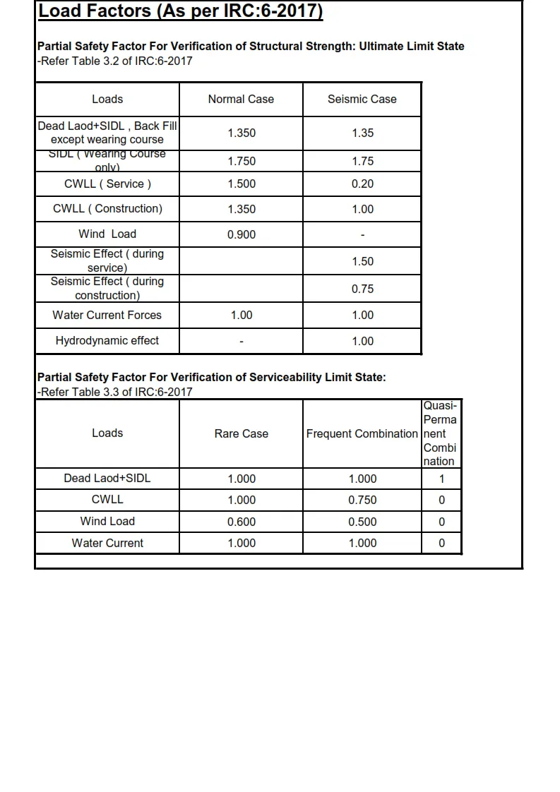
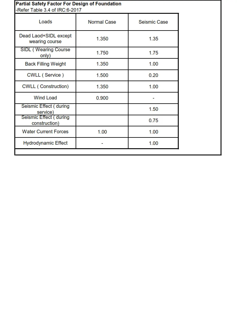
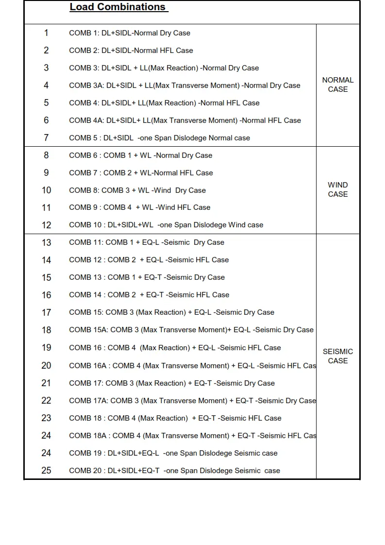
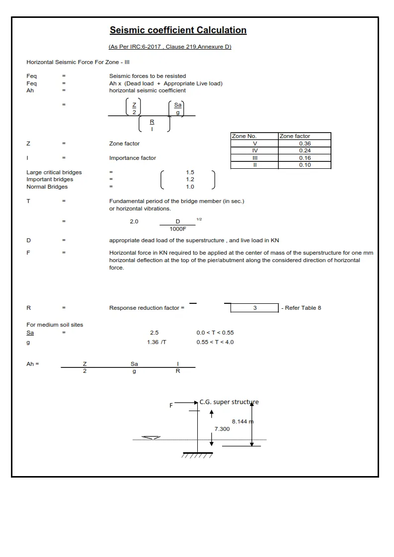
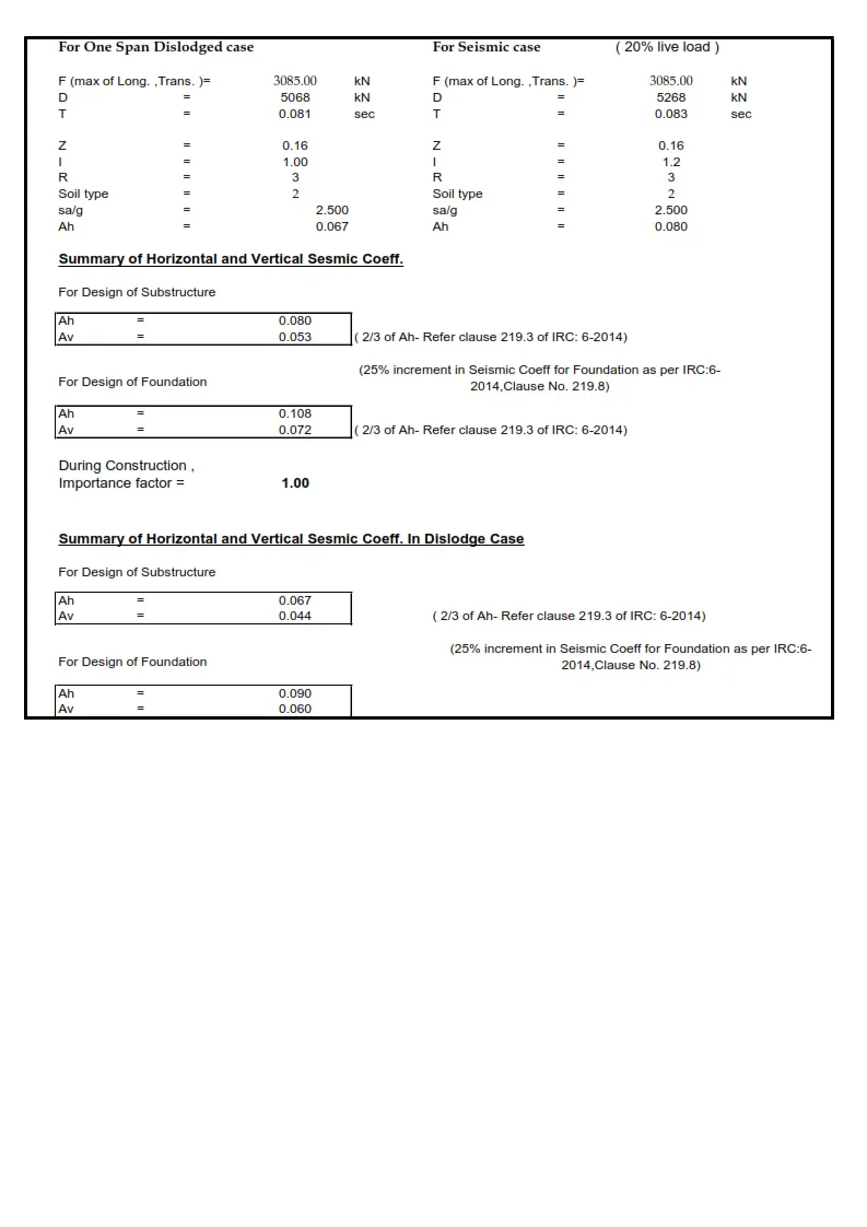
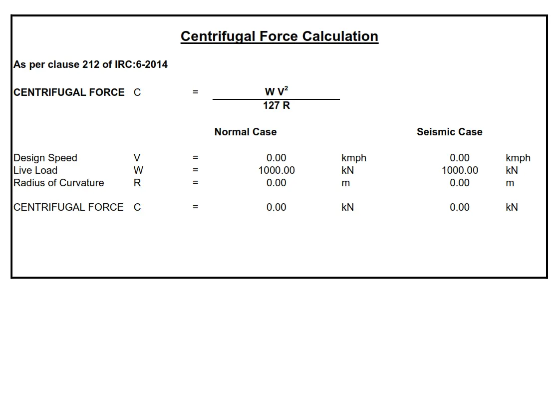
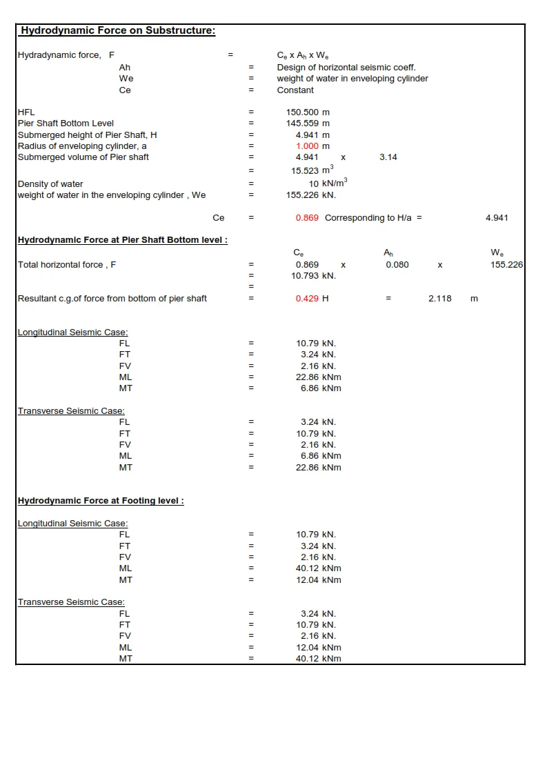
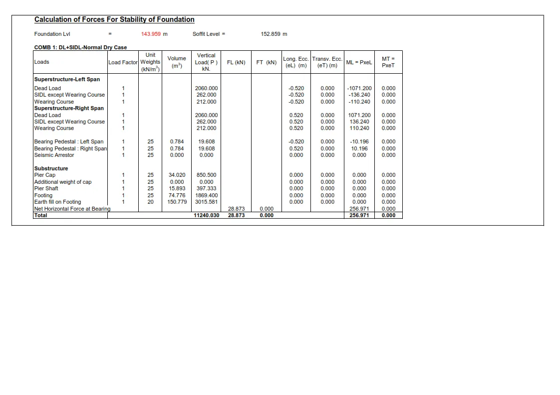
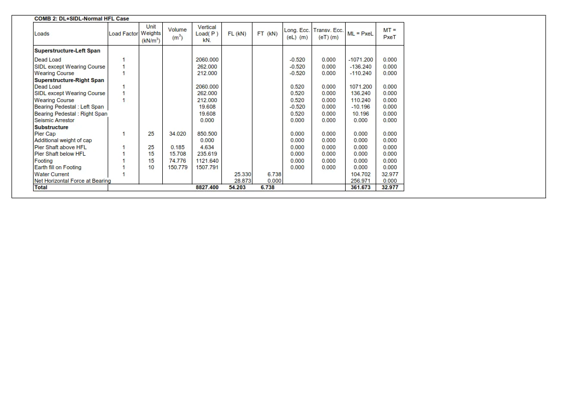
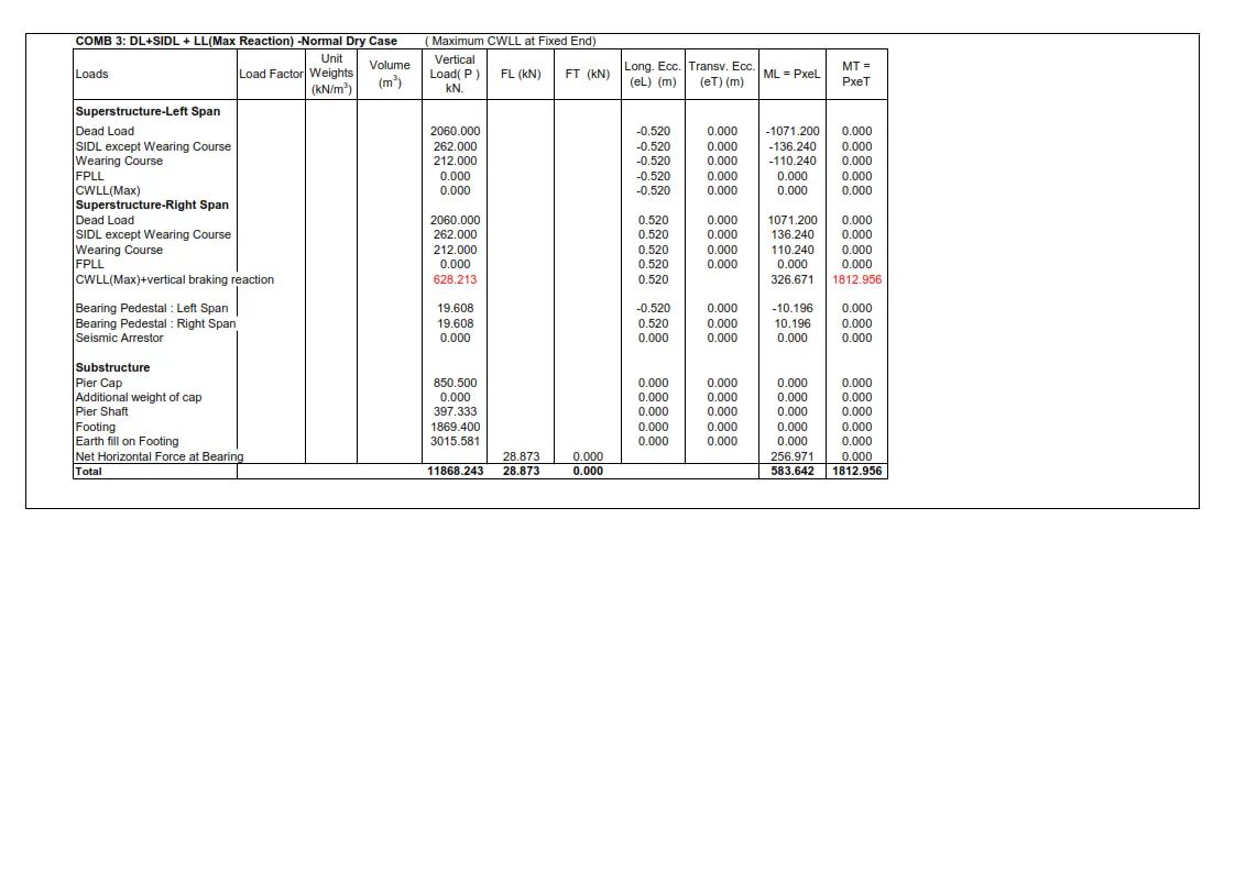
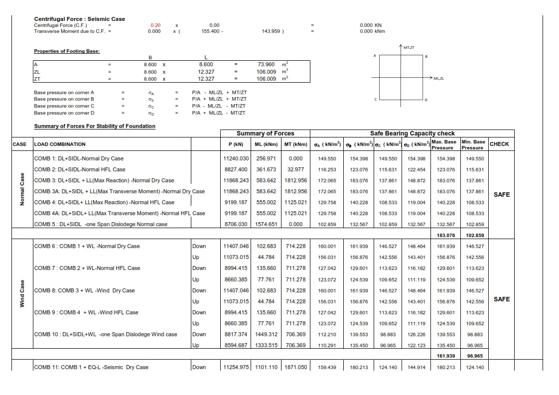
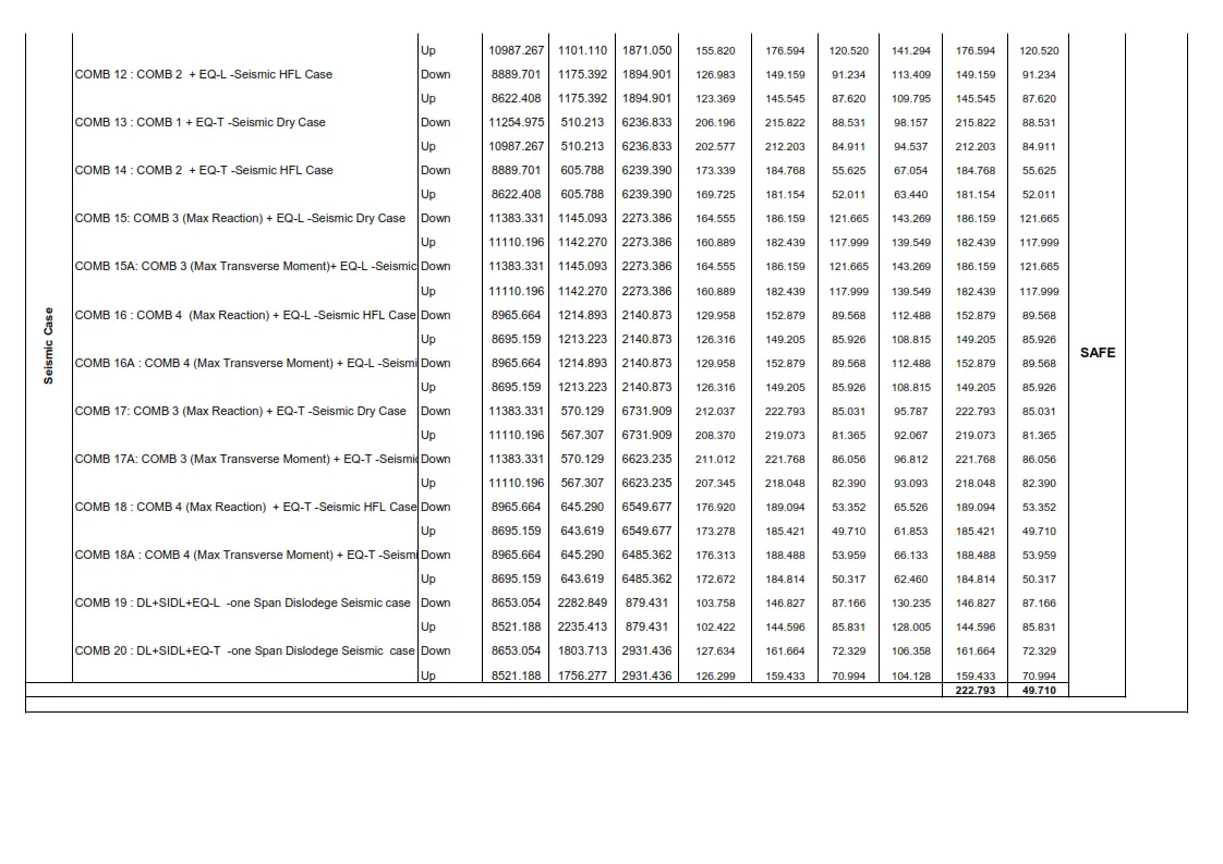
Calculations of Loads in Foundations :
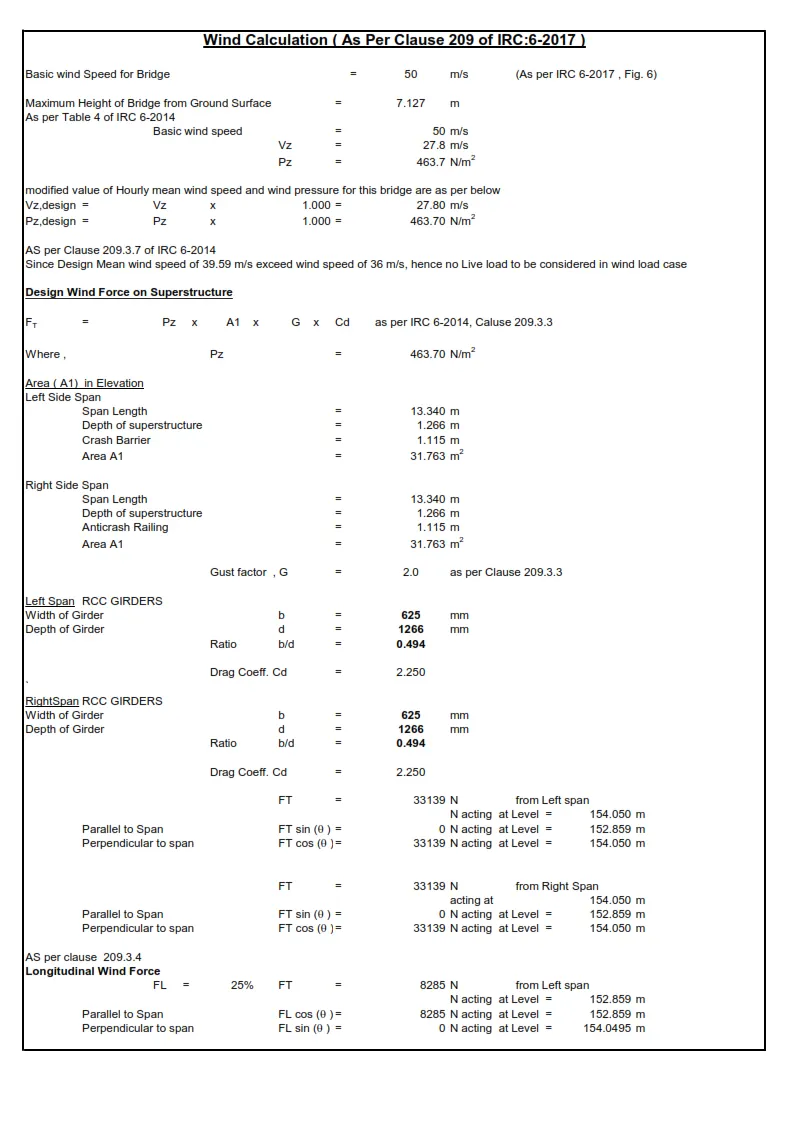
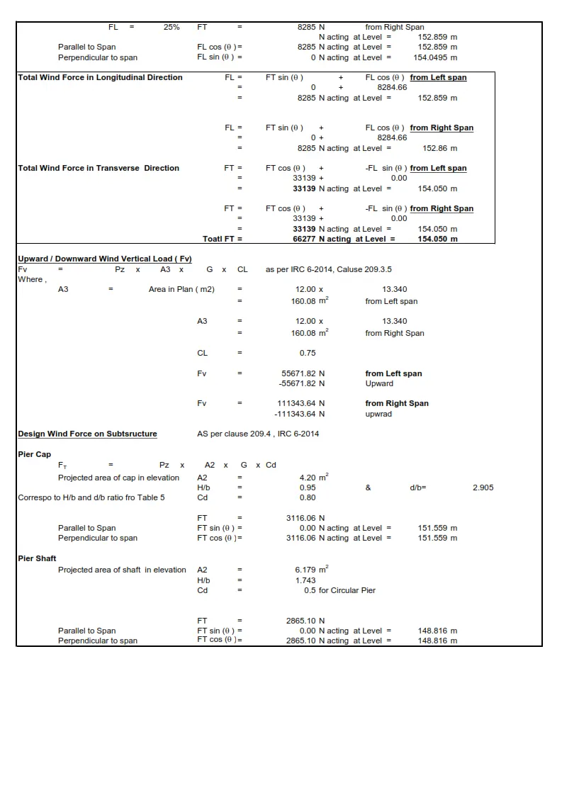
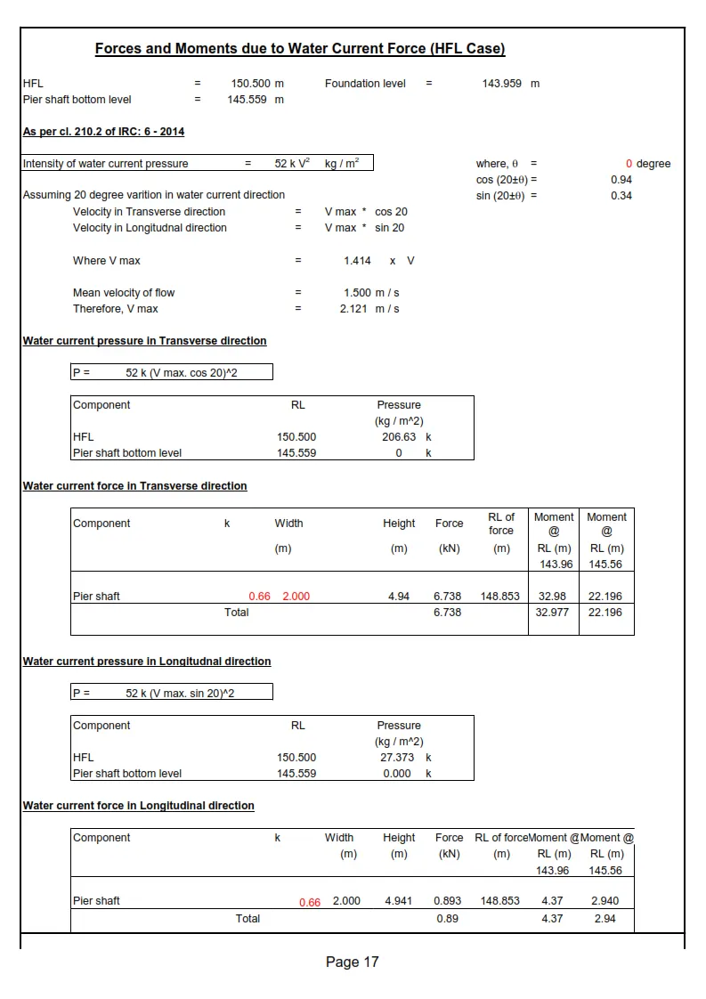
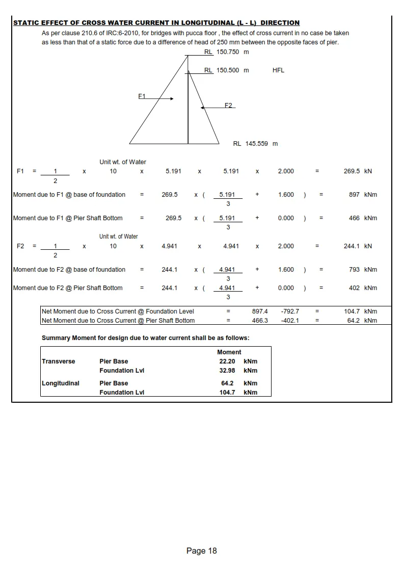
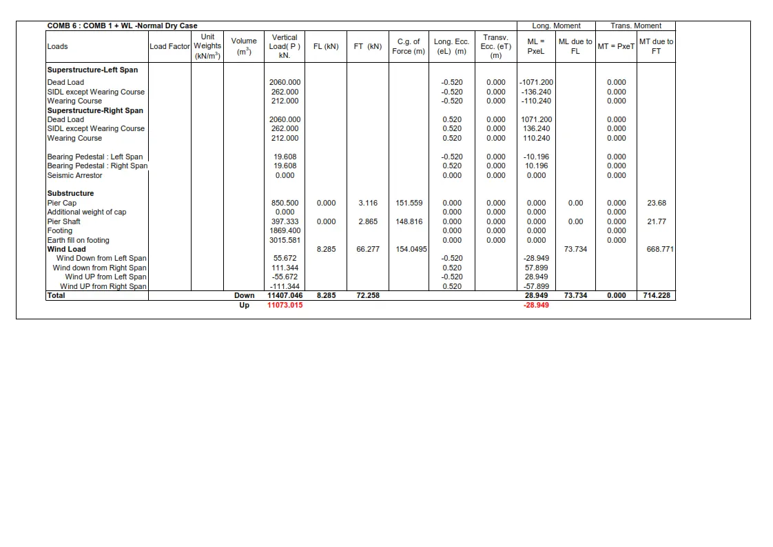
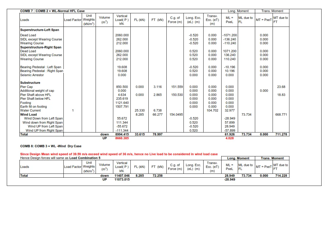
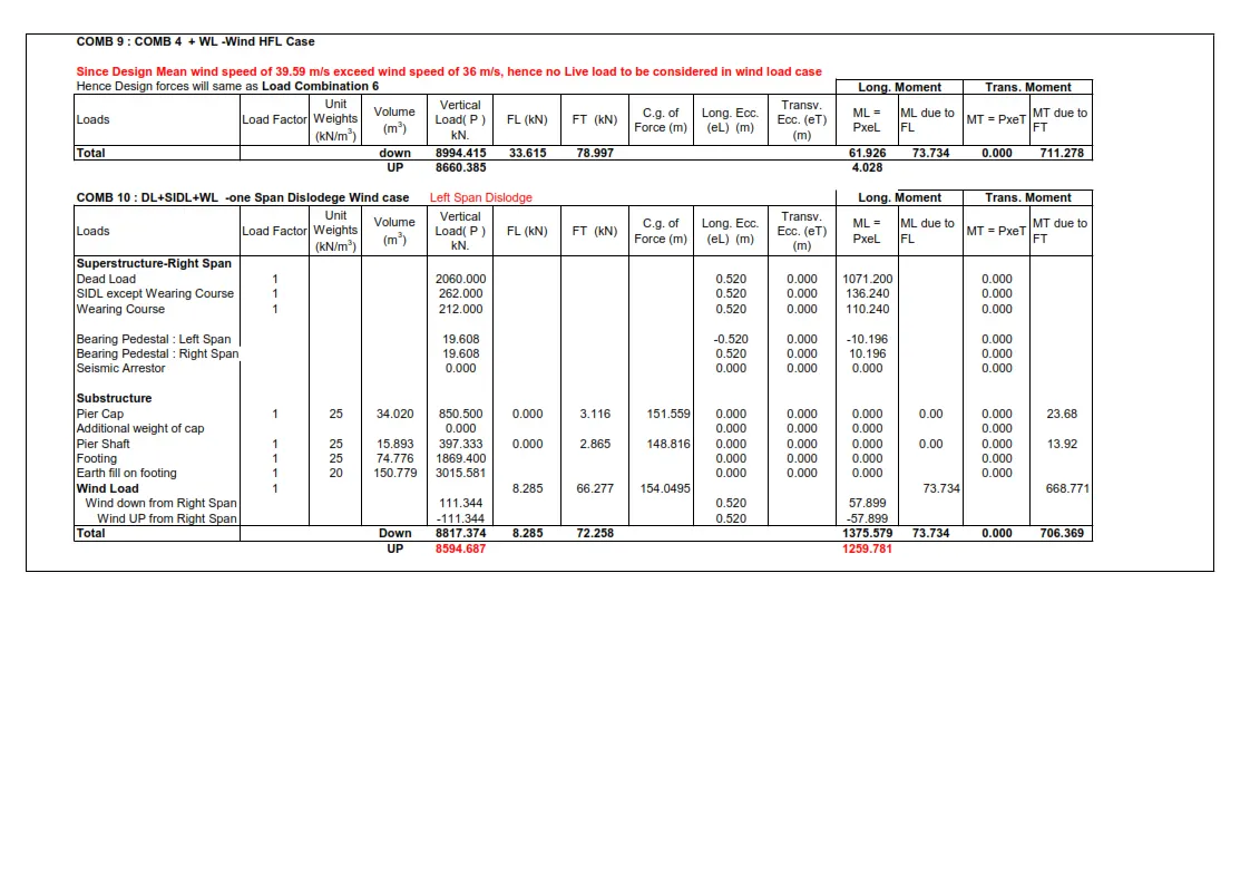
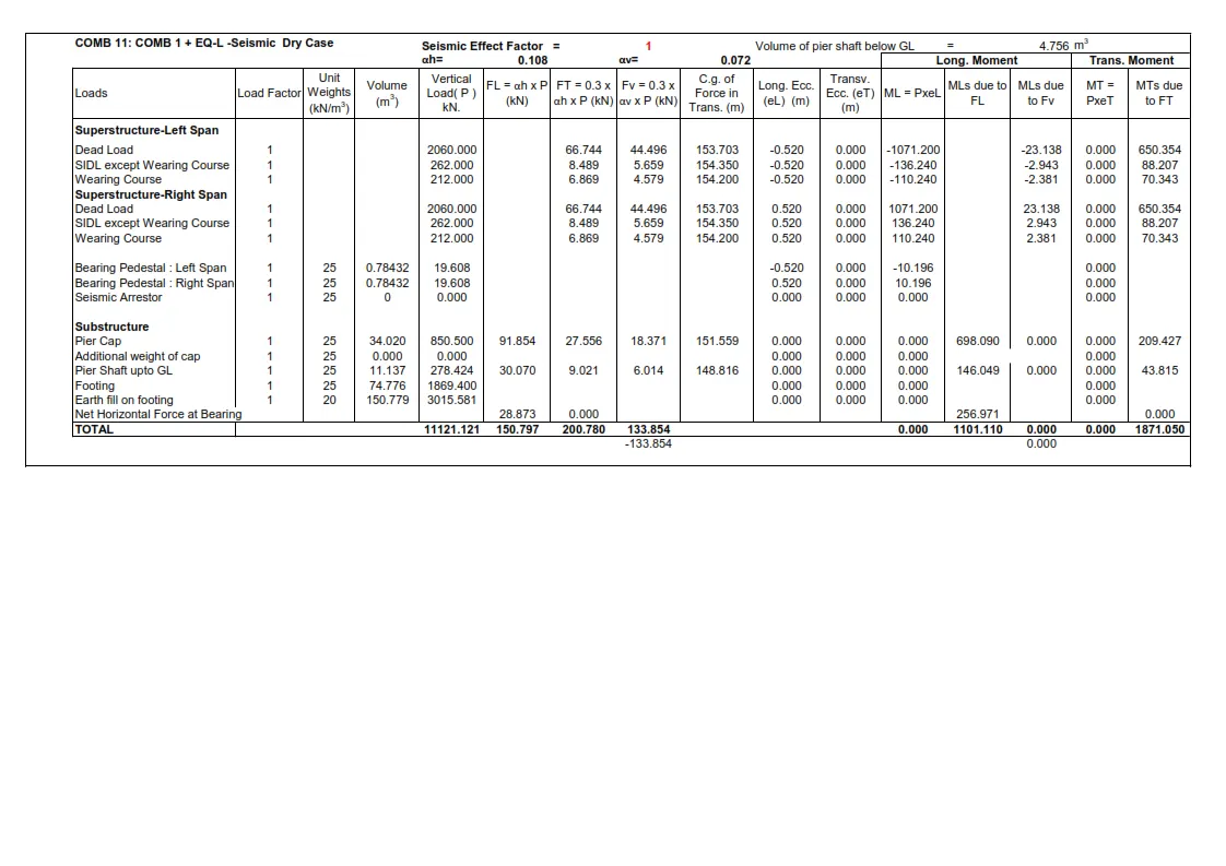
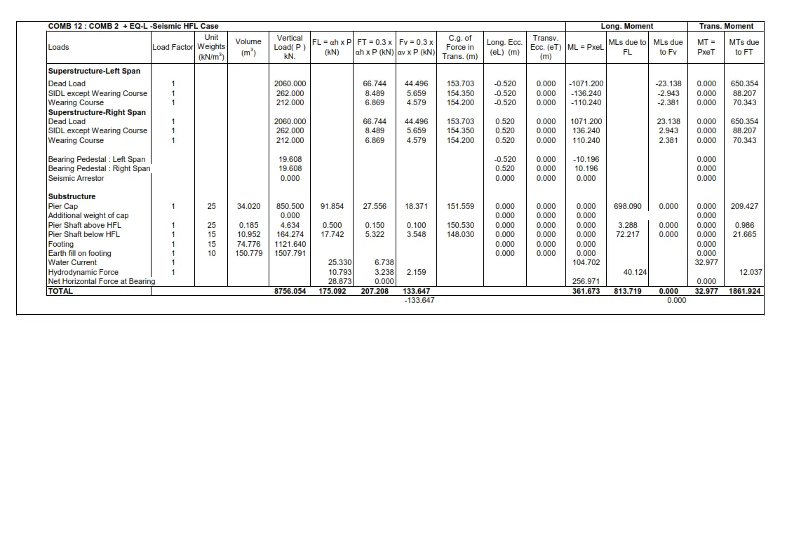
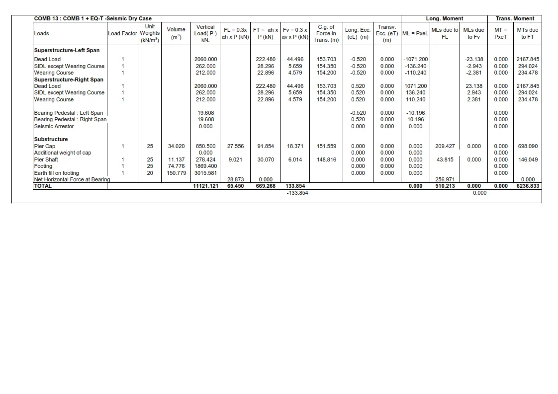
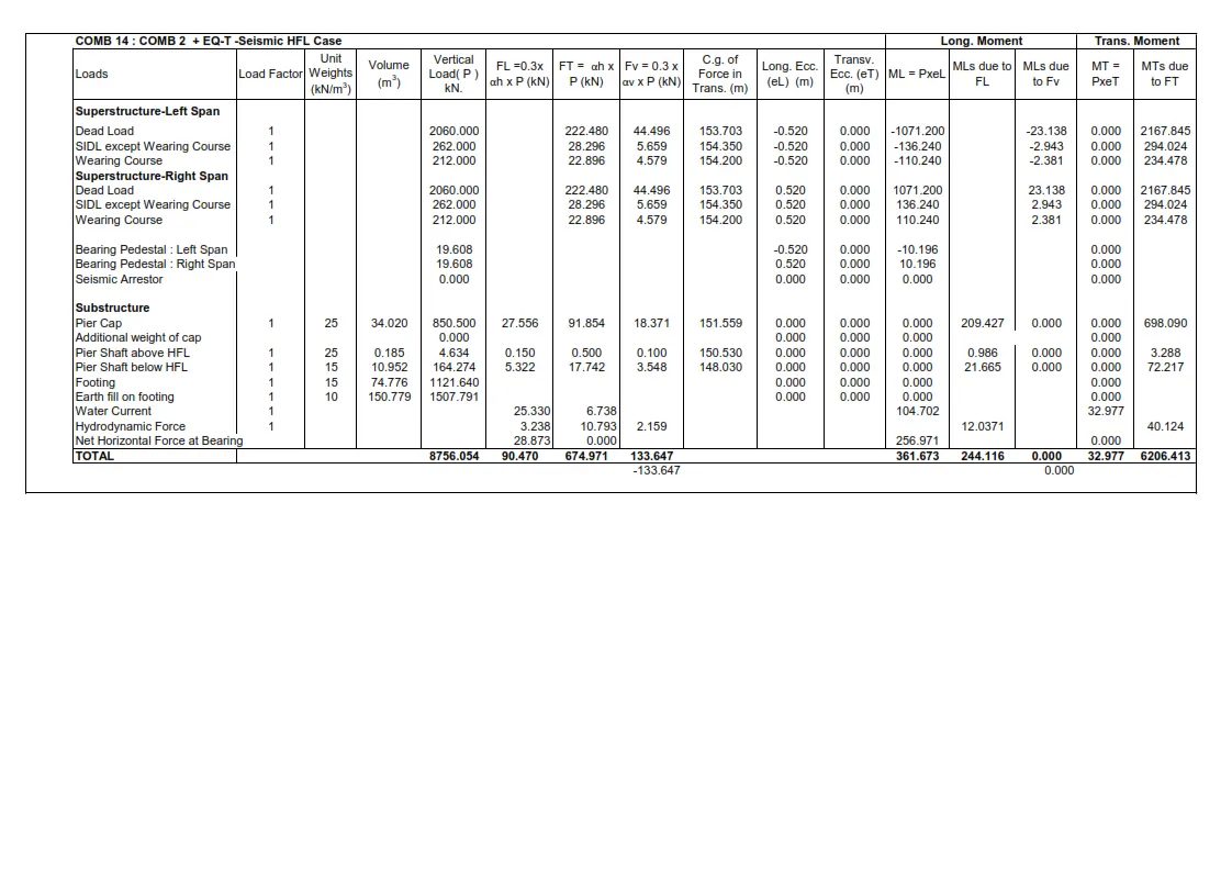
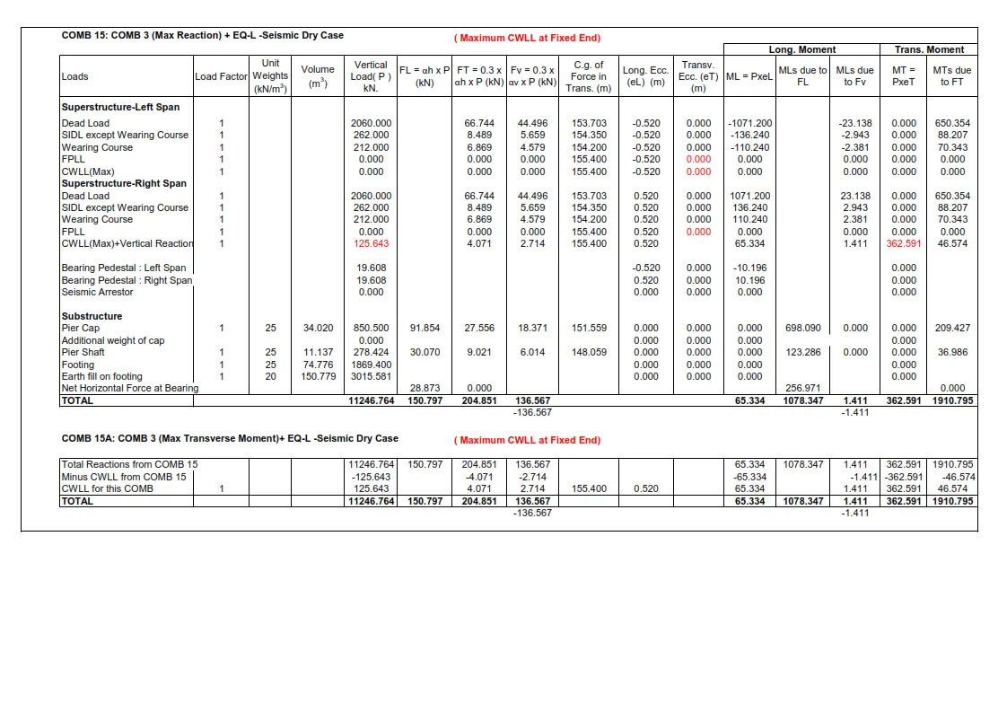
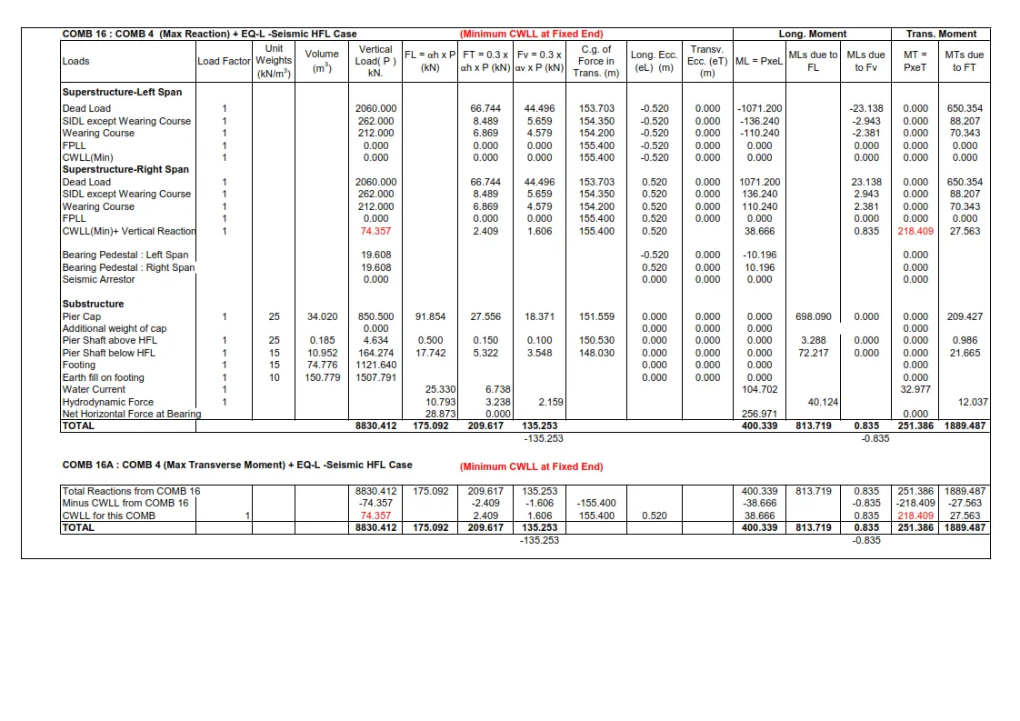
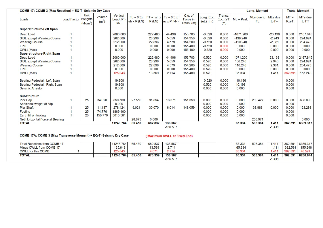
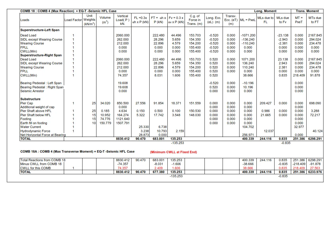
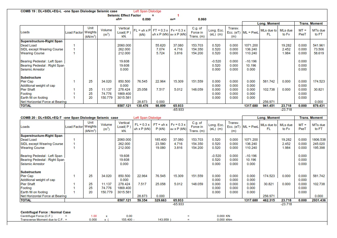
Answer 2 - Differences Between Free Piers & Fixed Piers :
FREE PIER :
A free pier is one that sustains a free bearing. There are no longitudinal reactions when there is free pier transfer since only axial forces are transferred and movement in a longitudinal direction is permitted. Therefore, with a free pier, horizontal forces such water pressure, seismic load, surcharge, and braking load are not taken into account. The size of the foundation is significantly smaller than the permanent pier due to the decreased horizontal force.
FIXED PIER :
A fixed pier is one that is intended to sustain a fixed bearing. There are significant transverse and longitudinal moments in fixed piers because rotation and lateral movements are resisted. In a fixed pier, all horizontal and vertical forces are taken into account. In order to support the heavy forces, the fixed pier's base is larger than usual.
Friction-related longitudinal force (CL.211.5.1 IRC 6)
The horizontal force at the bearing level in the longitudinal direction for a simply supported span with a fixed bearing on a rigid support must be greater than one of the two values shown below: -
Fh = Applied horizontal forces
Rg = Reaction at the free end due to dead load
Rq = Reaction at free end due to live load
μ = Co-efficient of friction at movable bearing
|
One span loaded condition |
|
|
|
||
|
|
|
|
|
|
|
|
Horizontal force = |
μ(Rh+Rq) |
|
Left span |
Right span |
|
|
Rg |
|
|
|
140.1 t |
140.10 t |
|
Rq |
|
|
|
0 |
41.8 t |
|
μ |
|
|
|
0.03 |
0.05 |
|
Horizontal force dead load, μRg |
4.20 t |
7.00 t |
|||
|
Horizontal force live load, μRq |
|
0 |
2.09 t |
||
|
Applied horizontal force Fh |
14.58 t |
|
|
||
|
|
|
|
|
|
|
|
Fixed End |
|
|
|
|
|
|
|
|
|
|
|
|
|
Total horizontal force= Maximum of the following two cases |
|||||
|
|
|
|
|
|
|
|
Fh-μ(Rg+Rq) |
10.38 t |
|
|
|
|
|
Fh/2+μ(Rh+Rq) |
11.49 t |
|
HL |
11.49 t |
|
|
|
|
|
|
|
|
|
Free End |
|
|
|
|
|
|
Total Horizontal force |
|
|
|
||
|
|
|
|
|
|
|
|
μ(Rg+Rq) |
4.20 t |
|
HL |
4.20 t |
|
|
|
|
|
|
|
|
|
Two span loaded condition |
|
|
|
||
|
|
|
|
|
|
|
|
Horizontal force = |
μ(Rh+Rq) |
|
Left span |
Right span |
|
|
Rg |
|
|
|
140.1 t |
140.10 t |
|
Rq |
|
|
|
34.8 |
41.8 t |
|
μ |
|
|
|
0.03 |
0.05 |
|
Horizontal force dead load, μRg |
4.20 t |
7.00 t |
|||
|
Horizontal force live load, μRq |
|
1.0 t |
2.09 t |
||
|
Applied horizontal force Fh |
21.87 t |
|
|
||
|
|
|
|
|
|
|
|
Fixed End |
|
|
|
|
|
|
|
|
|
|
|
|
|
Total horizontal force= Maximum of the following two cases |
|||||
|
|
|
|
|
|
|
|
Fh-μ(Rg+Rq) |
16.62 t |
|
|
|
|
|
Fh/2+μ(Rh+Rq) |
16.18 t |
|
HL |
16.62 t |
|
|
|
|
|
|
|
|
|
Free End |
|
|
|
|
|
|
Total Horizontal force |
|
|
|
||
|
|
|
|
|
|
|
|
μ(Rg+Rq) |
5.25 t |
|
HL |
5.25 t |
|
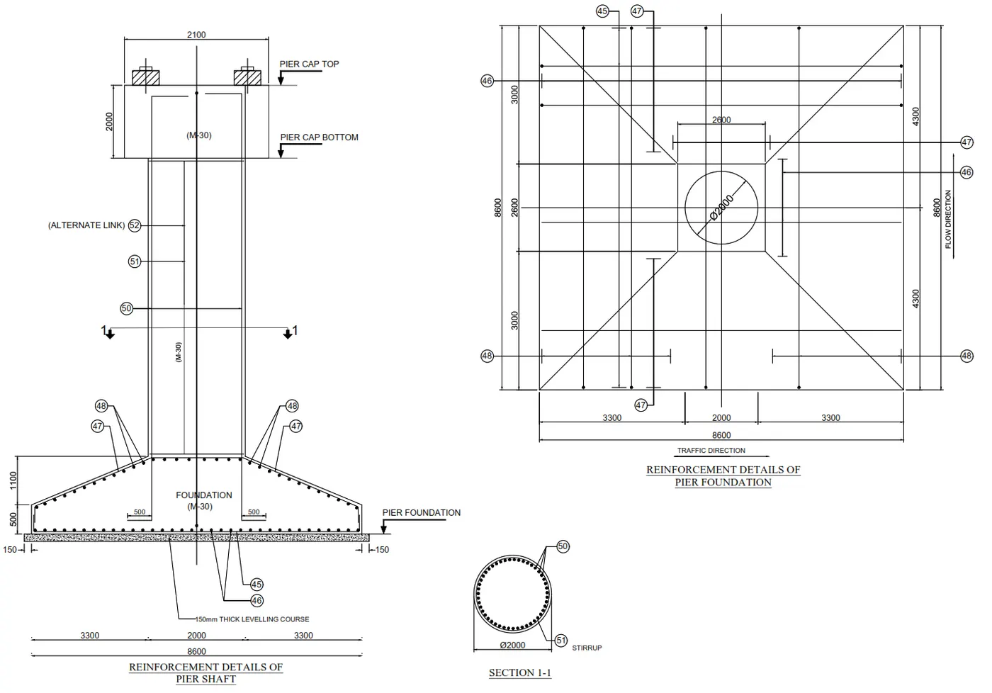
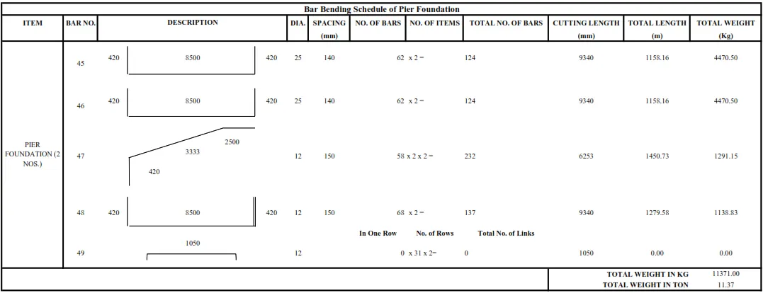
Answer 3 - Reinforcement Detailing :
Answer 4 - Following are the Checks which should be performed in Ultimate Limit State & Serviceability Limit State as per IRC 6 - 2017 :
Ultimate Limit State
This limit state includes static equilibrium and failure of structure when acted by ultimate design load.
Limit state of strength
Limit state of equilibrium.
Serviceability Limit State
These limit state specifically deals with the condition of the structure subjected to the influence of serviceability design loads.
Limit state of internal stress (Rare combination),” Stress in concrete can be controlled”.
Limit state of crack control (Quasi permanent combination),” Crack control shall be considered. The allowable crack width is 0.3mm.
Limit state of deformation.
Limit state of vibration.
Limit state of fatigue.