Week 5 Challenge
1. Generate manual wind loading in the design report based IS code as per the following input
- Basic wind speed = 39m/s
- Terrain category 2
AIM : To generate manual wind loading in the design report based IS code as per the following input
TOOLS REQUIRE : IS Code Book, Calculator, Excel
PROCEDURE :
- Firstly we have to open Microsoft Excel and enter the required values for calculation
- Now we should check required standard values from IS Code book
- Now we should measure the dimensions of the project in terms of length, breadth and height
- Now assume basic wind speed as 39m/s (Given)
- Now calculate the wind direction in both the directions i.e, X (+Cpi) & Y (-Cpi) directions
- Now we should calculate :
- External Pressure coefficients
- Internal Pressure coefficients
- Net Pressure coefficients
- Design wind presssure for wall
- Loading to be appplied on the wall
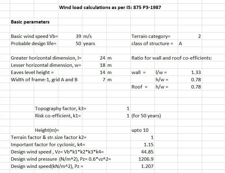
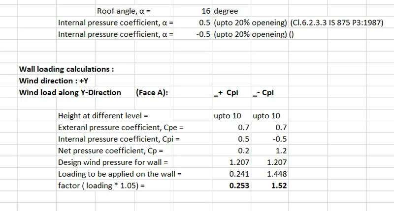
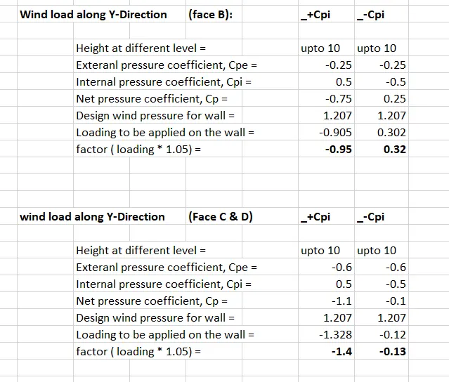
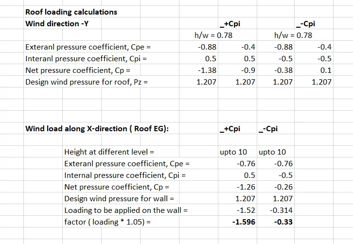
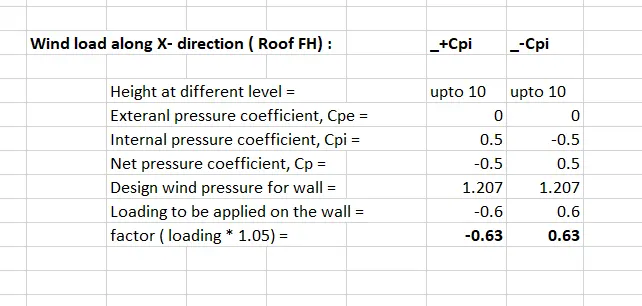
RESULT :
Therefore by following above procedure we can obtain all the required values & then we can start the manual calculation procedure sucessfully
2. Based on the above calculation apply the loadings on the model
AIM : To create the required loadings on the model as per above calculations
TOOLS REQUIRE : Loads, Loadcases, Wind load, Area Load, Global X, Global Y, Global Z
PROCEDURE :
- FirstLy we should open the previous file in order to apply the wind loads to the project
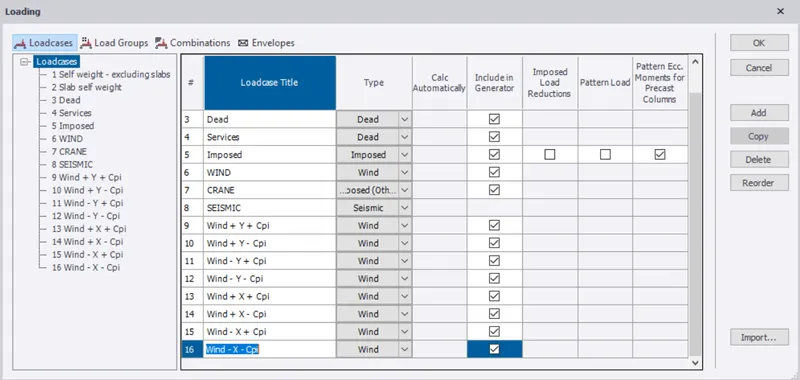
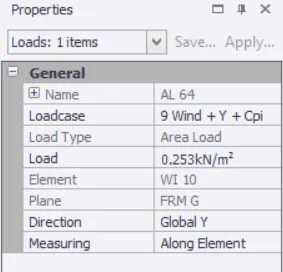
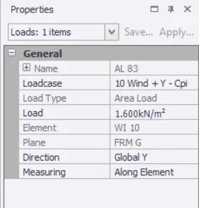
- Now select load cases option from tool bar and then add required 8 wind loads
- The required 8 wind loads are as follows :
- Wind + Y + Cpi
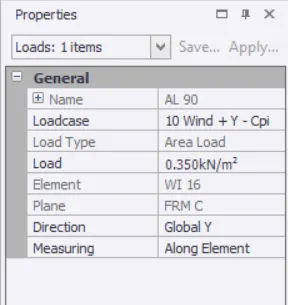
- Wind + Y - Cpi
- Wind - Y + Cpi
- Wind - Y - Cpi
- Wind + X + Cpi
- Wind + X - Cpi
- Wind - X + Cpi
- Wind - X - Cpi
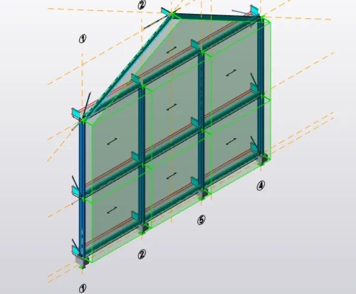
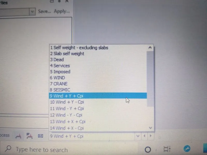
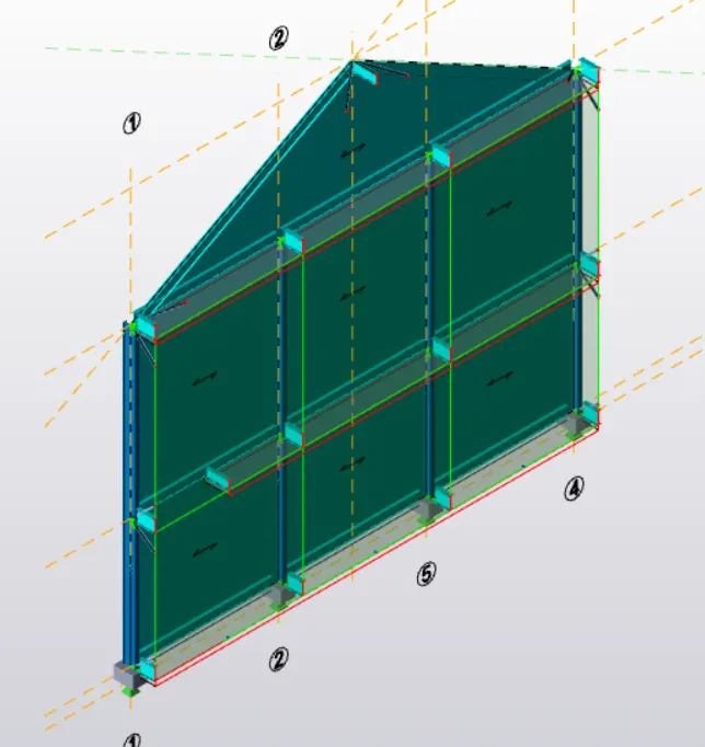
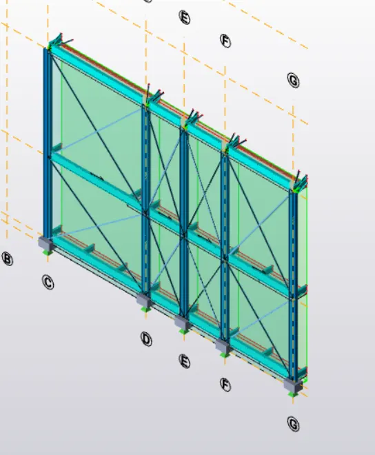
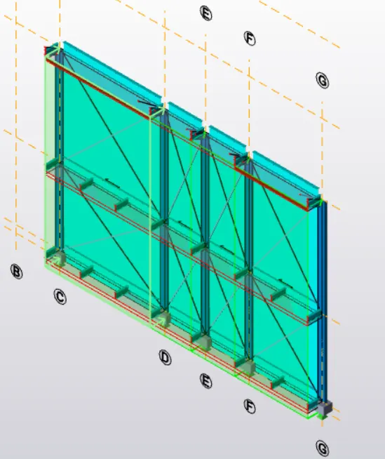
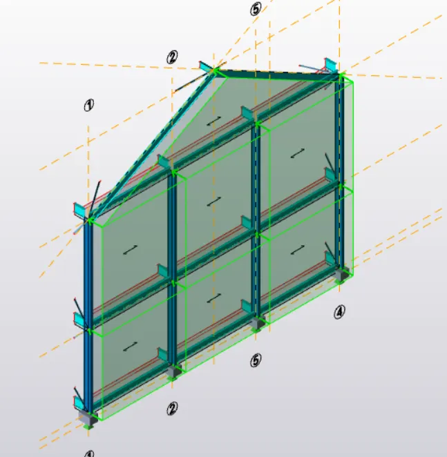
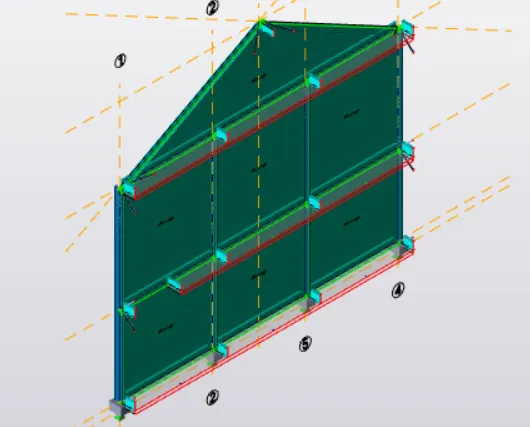
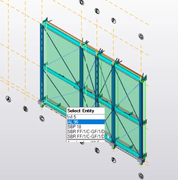
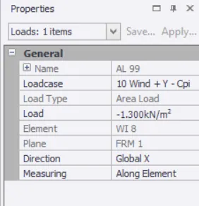
- After adding required loads, now apply those loads to the structure
- Now set the directions for face C & D to global X
- Now set the directions for face A & B to global Y
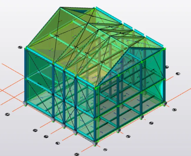
- Now set the directions for Roof Components to global Z
- Then apply +Cpi and -Cpi values to all other sides
RESULT :
Therefore previously calculated loads are applied to the structure successfully
3. On a separate model generate wind loading using wind wizard
AIM : To create separate model and to generate wind loading using wind wizard
TOOLS REQUIRE : Manage property sets, Beams, columns, construction levels, load cases, wall panels, roof panels, property window, scene content, Model tool, validation, wind wizard, area load, line load, frames etc.
PROCEDURE :
- Firstly create a new file in tekla structural designer software
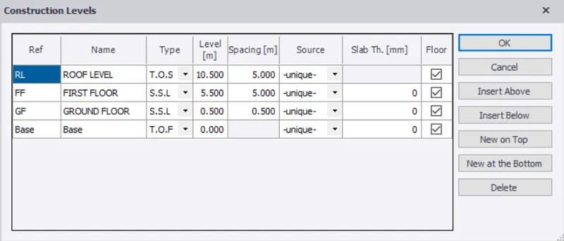
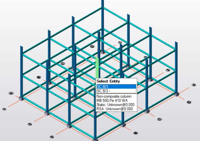
- Now select construction levels and create different levels with required heights
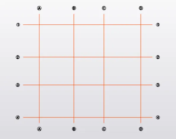
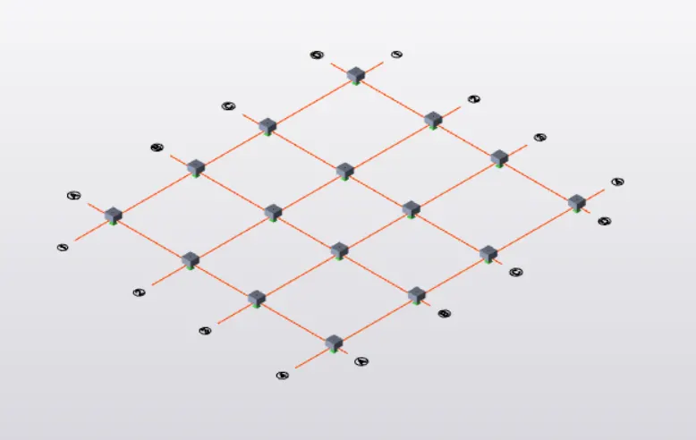
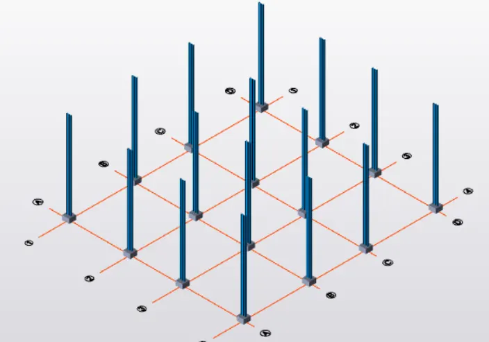
- Now select grid lines and draw required grid lines accordingly
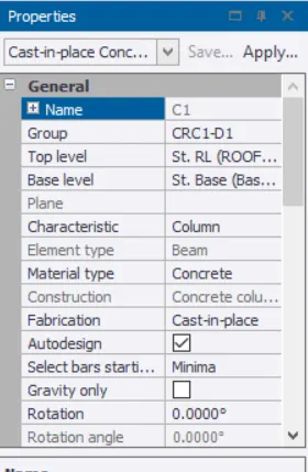
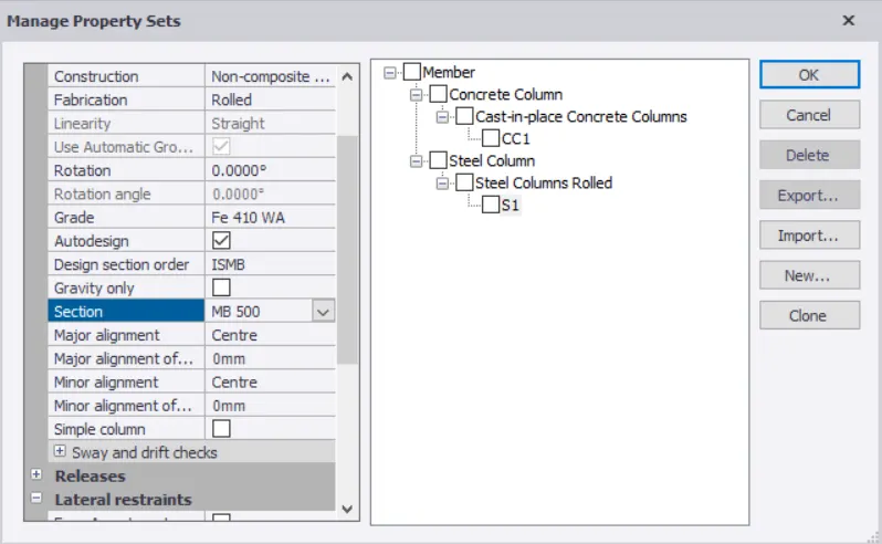
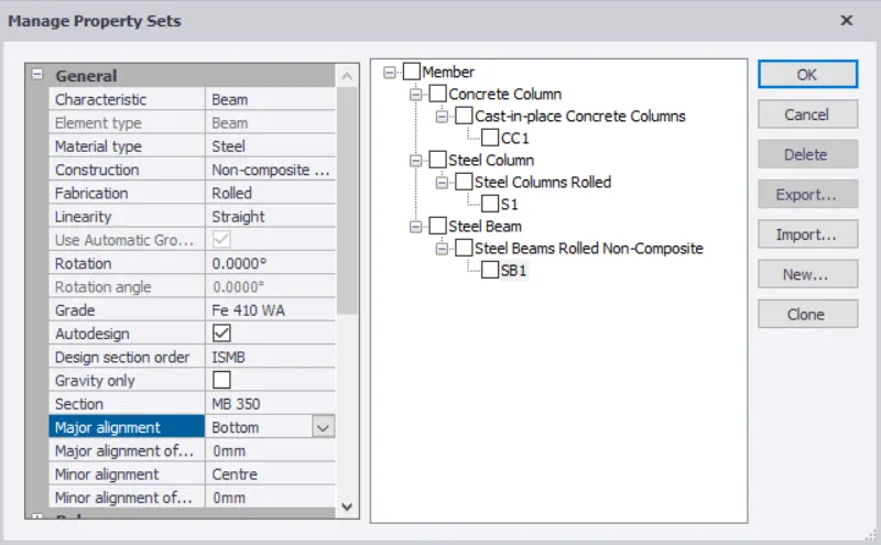
- Now select manage property sets and create required concrete columns, steel columns, beams with required properties as per IS code
- Now select each level & then select columns from model tool bar and place them at required positions
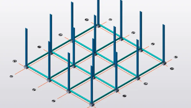
- Now select each level & then select beams from model tool bar and place them at required positions as per IS code
- After placing beams and columns at required positions select frames tool and create different frames of the structure
- Now select load tab and select load cases option from that
- Now create new load such as crane, seismic and wind load to the list of predefined loads
- Now create slabs for all the required layers
- Now based on the dimension of the adjacent beams we have to select one way or two way slabs, that is to select the two way option when the ratio between the values must be less than 2 or else it will consider one way slab automatically
- Now select steel beams with require measurements and create rafter beams
- Then select roof panels and place them on the rafter beams
- Then select wall panels and place them on all sides of the structure
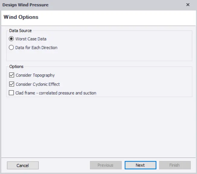
- Now select wind wizard option
- Now select topography and cyclonic effect options and then click on next
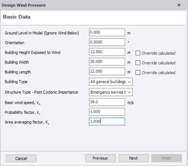
- Now give the required dimensions and wind speed value as 39m/s and select general buildings and industrial structure option
- Then select terrain category and enter 10m as fetch a distance value & click on next
- Then click on next and then finish option
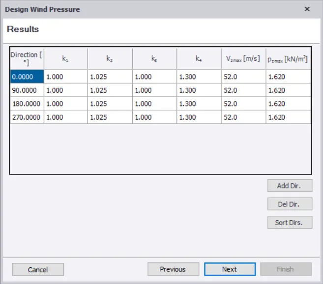
- Now we can see design wind pressure results window with wind load values
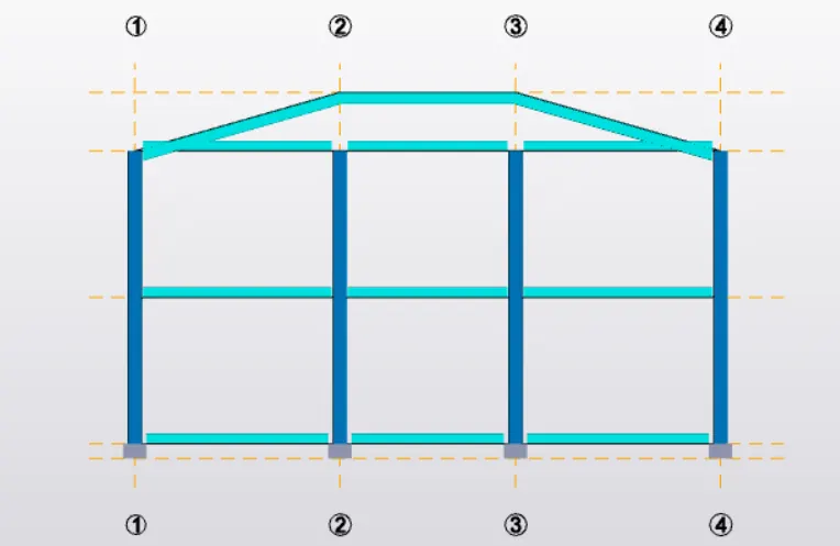
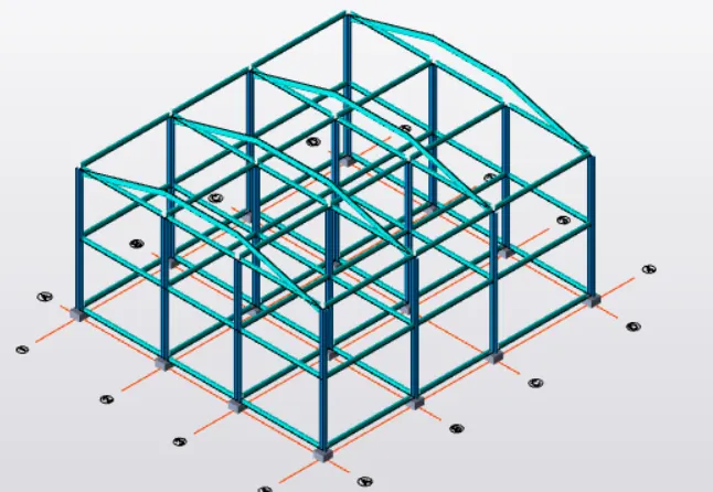
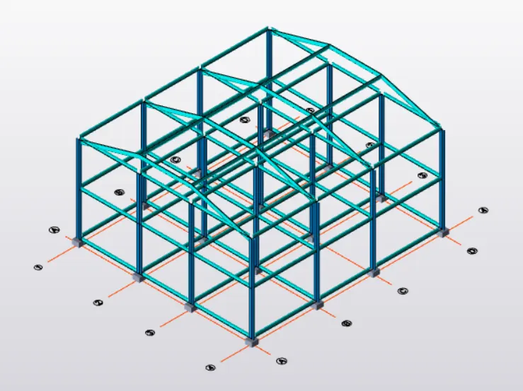
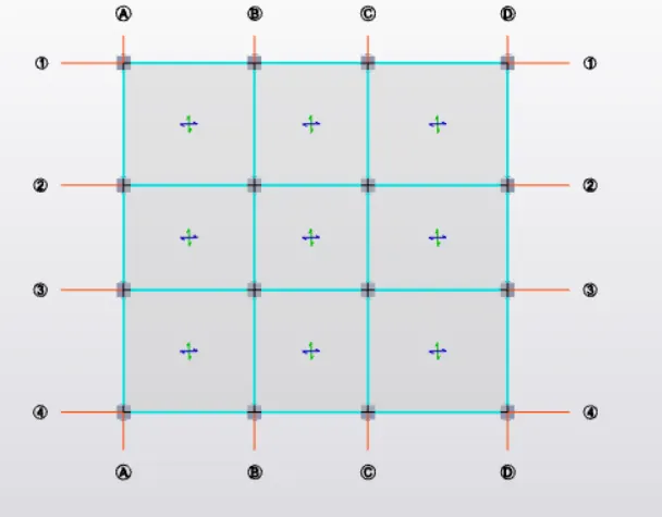
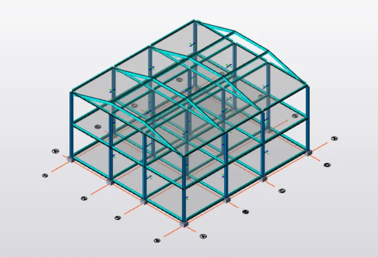
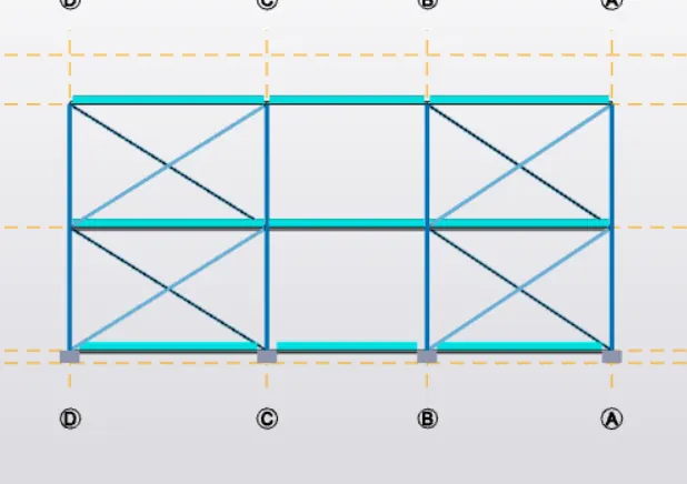
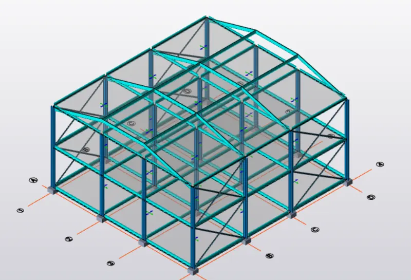
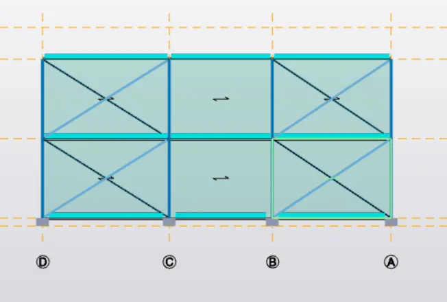
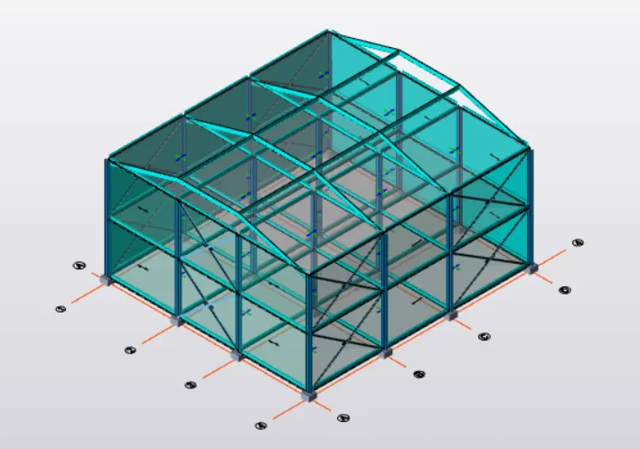
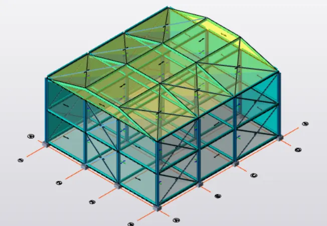
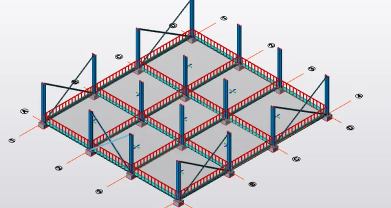
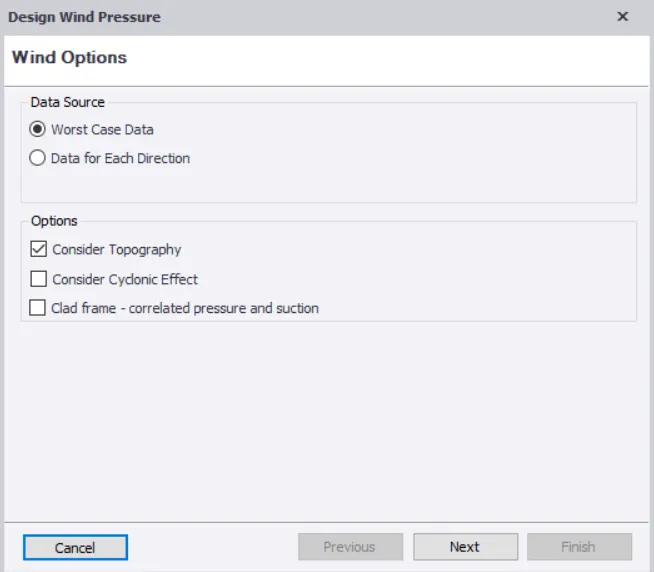
RESULT : Therefore by using above procedure we can create a new structure and we can apply and calculate wind loads on a structure using wind wizard tool successfully