Week 5 Challenge
Aim and Introduction :
- To Design a bridge of height 9m above ground level and to apply the wind load on the bridge using staad pro.
- To find wind load: Vz = Vb*k1*k2*k3*k4.
where Vz is design wind speed at height z in m/s, and vb is the basic wind speed.
- Pz=0.6Vz^2
where Pz is wind pressure at height z in N/m^2.
- Based on the wind speed, the locations were classified into five different zones
1.under 33m/s
2.33-39m/s
3.39-44m/s
4.44-47m/s.
5.over 50m/s

Fig. 1
- With reference to IS 875 part 3, the wind speed for a given location in Mumbai will be 44m/s, given that location is located in open terrain with a well-scattered obstruction height of less than 10m.
Procedure:
To Calculate wind speed (Vz) = vb*k1*k2*k3*k4.
Vb= 44m/s
First we find factor K1,K2,K3 and K4.
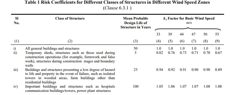
Fig. 2
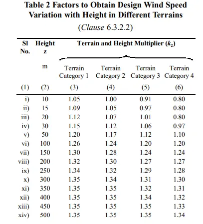
Fig. 3
K1= 1.07 (from table 1 of IS 875 part 3 2015)
K2= 1.05 (from table 2 of IS 875 part 3 2015)
K3= 1.00 (as per clause 6.3.3 IS 875, for upwind slope less than 3 degree factor K3=1.0)
K4= 1.30 (when the location is within 60km radius of the ocean, the cyclone factor is taken into account)
Now,
Vz = 44*1.07*1.05*1.0*1.30
=64.26
Wind pressure, Pz= 0.6Vz^2
= 0.6*64.26*64.26
= 2477.6N/m^2 = 2.47 KN/m^2
We apply the wind load of 2.47 KN/m^2 to the bridge structure and perform the analysis in staad pro.
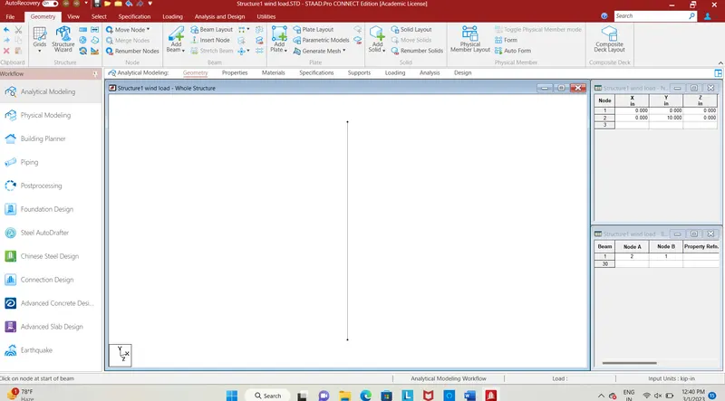
Fig. 4
- First enter the node values as (0,0,0) (0,10,0) given that height of the pier above ground level is 9m, so additionally add 1 metre in height which is below the ground level for footing join the two nodes by using add beam command.
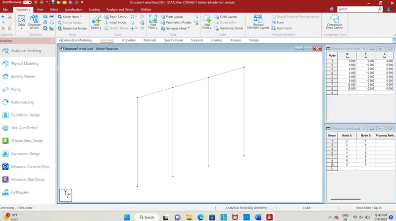
Fig. 5
- Use translational repeat command, enter spacing as 4m no of steps as 3 in the x-direction to provide another 3 no of piers, connect the nodes by beam using add beam command
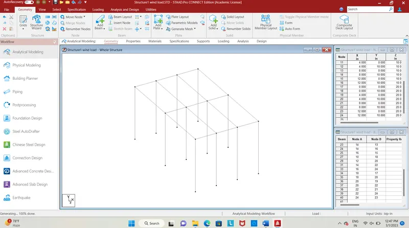
Fig. 6
- Use translational repeat command in z direction ,enter spacing as 10m and no of steps as 2, connect it using add beam thus bridge of 12m in x-direction and 20m in z-direction is formed
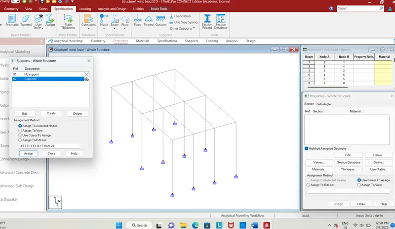
Fig. 7
- Assign fixed supports to the structure, select all bottom nodes then assign fixed support.
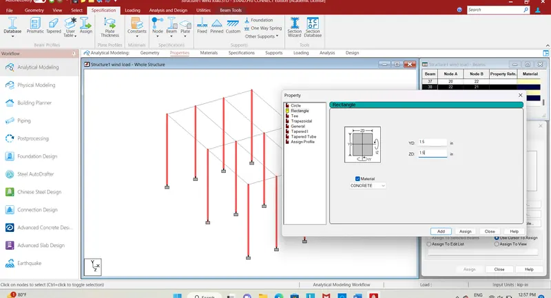
Fig. 8
- Next, we need to assign property to the pier members, click on the specification tab then use prismatic,add rectangular section of 1.5m * 1.5m select the piers and assign the property.
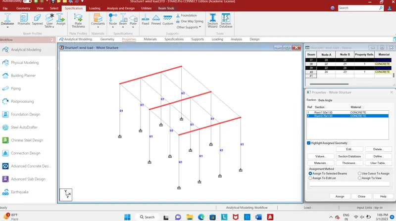
Fig. 9
- Assign property to cross girders ,add a rectangular section of 0.75m*1.5m and then assign it
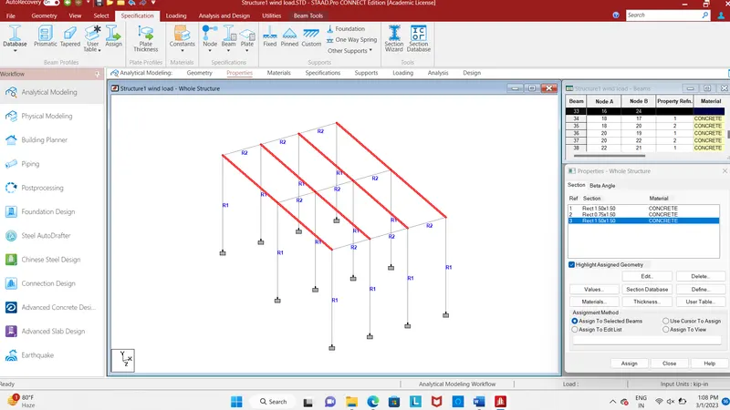
Fig. 10
- Also assign property to main girders, similarly on specification tab click use prismatic and add rectangular section of 1.5m * 1.5m select the girders and assign the property.
- Now we apply loading to the structure.
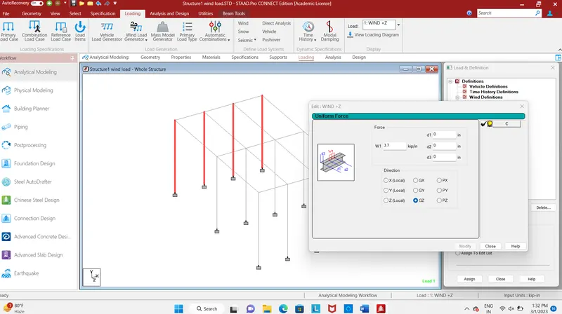
Fig. 11
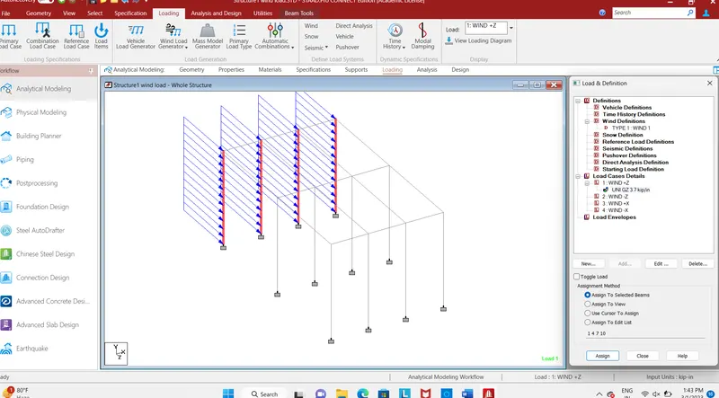
Fig. 12
- Go to load case details add wind +Z, go to member load uniform force provide load of 2.47*1.5= 3.7KN/m in GZ direction now assign the load to corner pier.
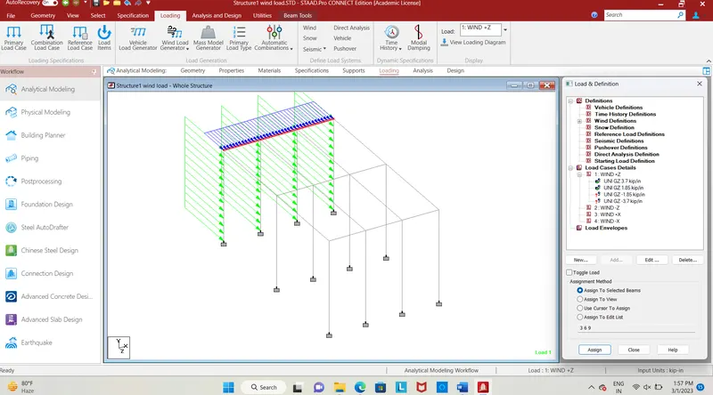
Fig. 13
- Apply load of 2.47*0.75=1.85, to the set of cross beam in GZ direction.
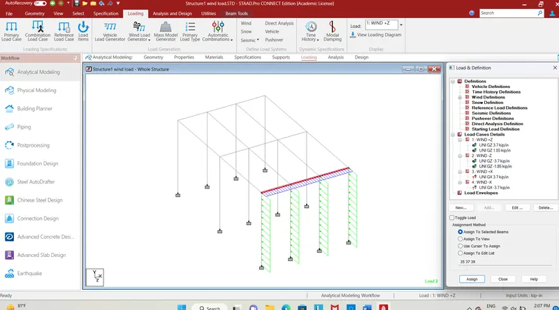
Fig. 14
- Similarly apply loads of -3.7KN/m to another set of pier and loads of -1.85KN/m, in GZ direction to another set of cross beam.
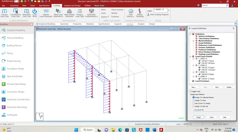
Fig. 15
- Load of 2.47*1.5= 3.7KN/m is applied to the set of main beam and pier in GX direction.
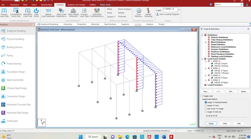
Fig. 16
- Load of -3.7KN/m is applied to another set of main beam and pier in GX direction.
Results:
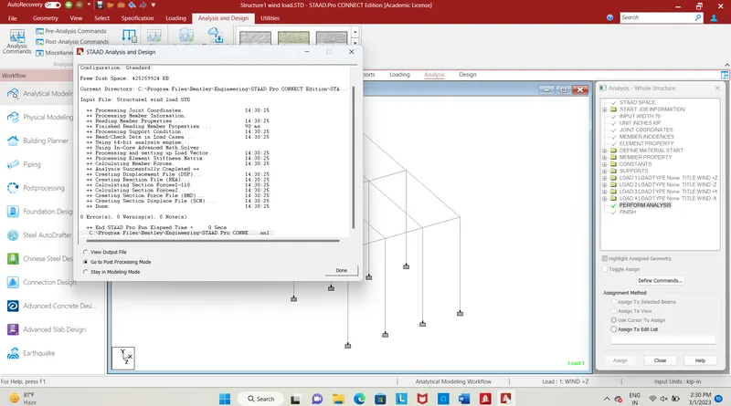
Fig. 17
- Click on the post processing mode button, then post processing tab will open so we can analysis the behaviour of the bridge for the applied loading.
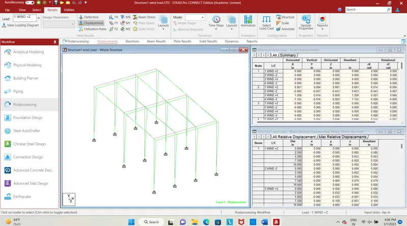
Fig. 18
- The above image shows the displacement of the member due to wind load in z direction.
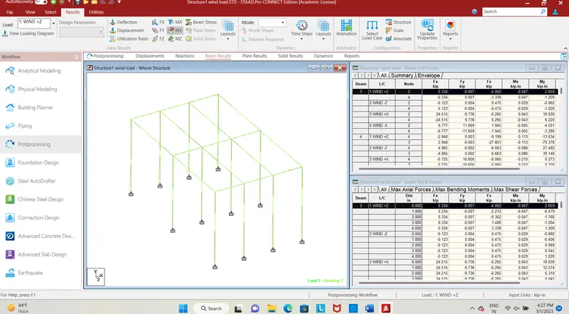
Fig. 19
- The above image shows the M(y) beam result for the wind load along z direction
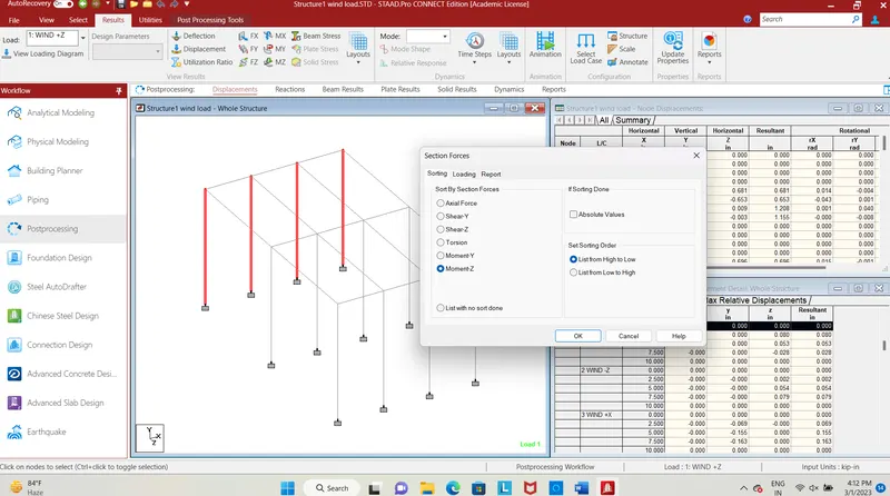
Fig. 20
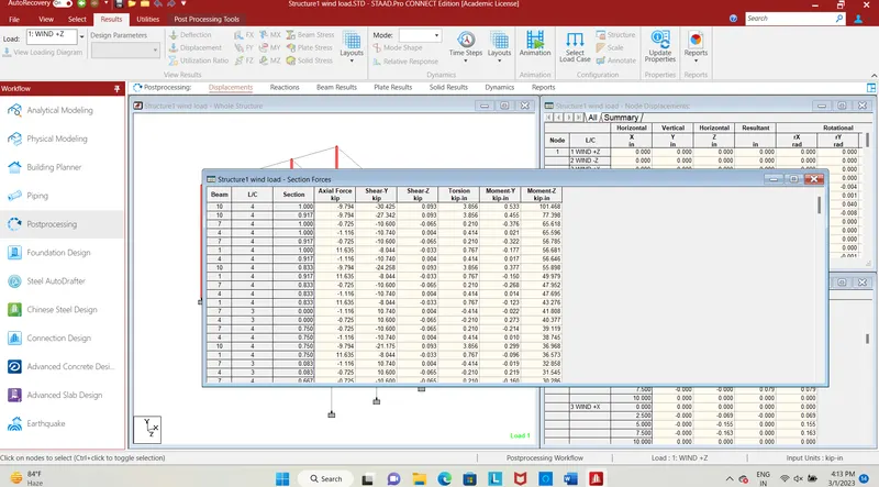
Fig. 21
- The above images show the values of moment(Mz) from high to low for the respective set of pier.
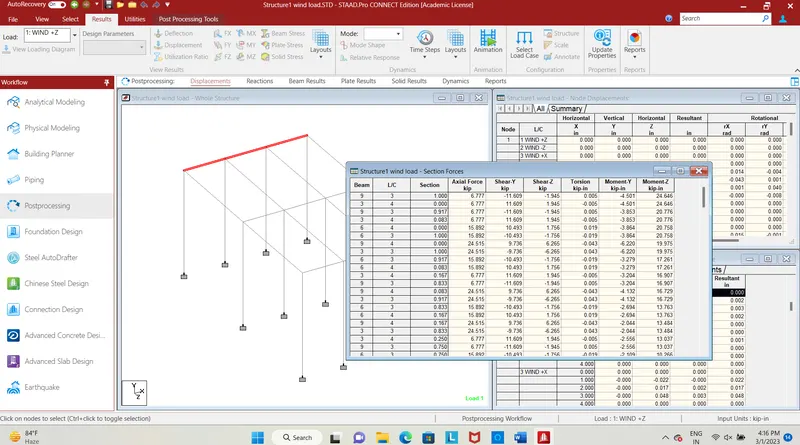
Fig. 22
- The above image shows the results of moment (My) from high to low for the respective set of cross beam for wind load in Z direction