Week 4 Challenge
Aim and Introduction :
To calculate the Earth pressure acting on the abutment wall, for the given dimensions and to apply the calculated pressure loads on the structure and perform structural analysis in staad pro.
- Earth pressure is the Horizontal thrust exerted by retained earth on the vertical structure element like wall, pier, abutment.
Based on the pressure exertion it is classified as,
- Earth pressure at Rest :
Earth pressure at rest occurs when the structure is stationary without any lateral displacement or movement.
- Active Earth pressure :
Active earth pressure occurs when the retaining wall moves away from the backfill, which means the soil pushes
the wall
- Passive Earth pressure :
Passive Earth pressure occurs when the wall moved towards the backfill, which means the soil
pushes the wall.
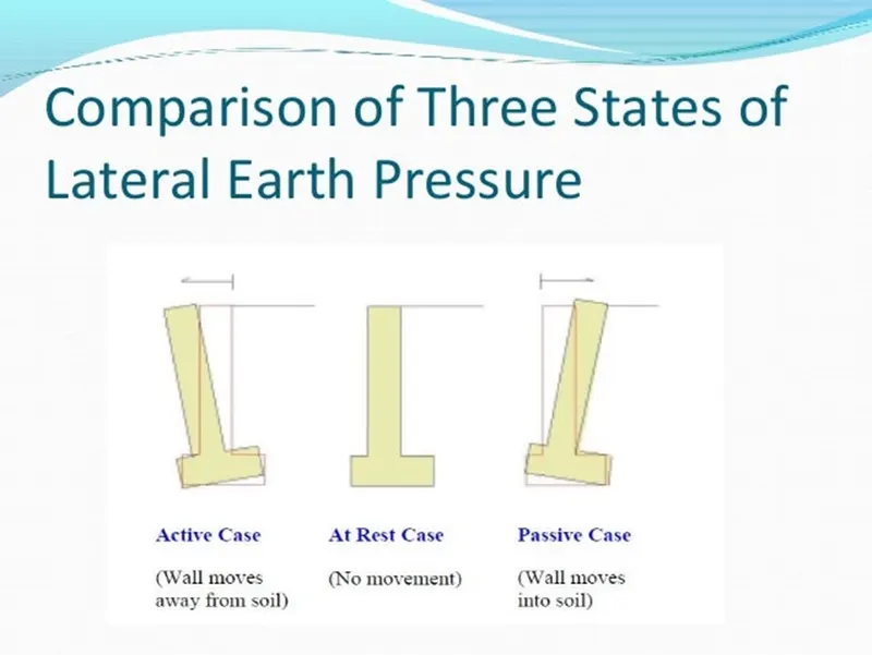
Fig. 1
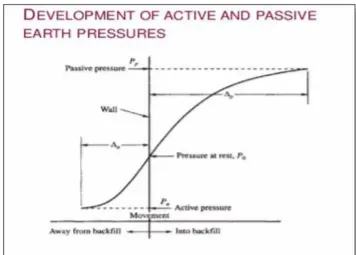
Fig. 2
Procedure:
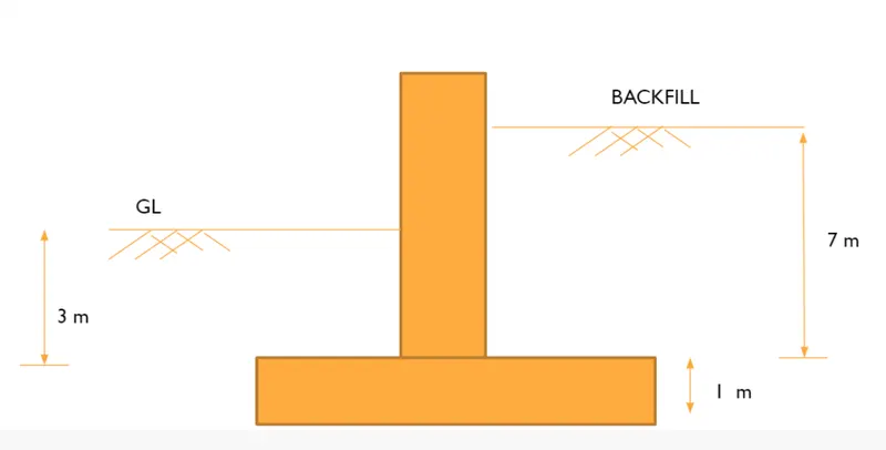
Fig. 3
- Here, we need to calculate earth pressure for inner and outer fill, the ground level is at 3 metres that is outer filling and the backfill is at a level of 7 metres take it as inner filling.
- let us assume outer and inner fill as K1 and K2.
- The formula to find out, Earth pressure(k)= coefficient of earth pressure (k0 or ka or kp) * density * height
- The water table is at ground level so in this case, we need to calculate submerged unit weight, submerged unit weight = saturated unit weight - unit weight of water.
- k1 = ka * submerged unit weight * height
- The coefficient value of ka and kp value is taken as 0.35 and coefficient value of Ko is taken as 0.5
- The unit weight of dry soil is taken as 18KN/m^3, unit weight of saturated soil is 18KN/m^3 and unit weight of water is 10KN/m^3.
Now, we calculate the value of K1,
-
k1 = 0.35 * (19-10) * 3
=> k1= 9.45 KN/m2
- k2 value is calculated for two condition, for up to ground level (3m) it is calculated for submerged condition , and for the remaining 4 metre it is calculated for normal condition.
-
=> k2 = [0.5 * (19 -10) * 3 ] + (0.5 * 18 * 4)]
=>k2 = 49.5 KN/m2
- K1=9.45KN/m^2 , K2= 49.5KN/m^2
NOW, we apply the earth pressure loads on the structure and will perform analysis in staad pro.
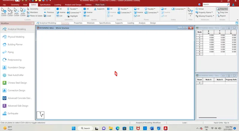
Fig. 4
- first enter the node coordinates as (0, 0,0), then select the node and use transitional repeat in z-direction (spacing= 0.5, no. of step= 1) .
Then select the two nodes and use trans. repeat in y-direction(spacing=0.5, no. of step=1), then use add plate cursor to join the four nodes and then select plate cursor to form the plate.
The plate has been created.
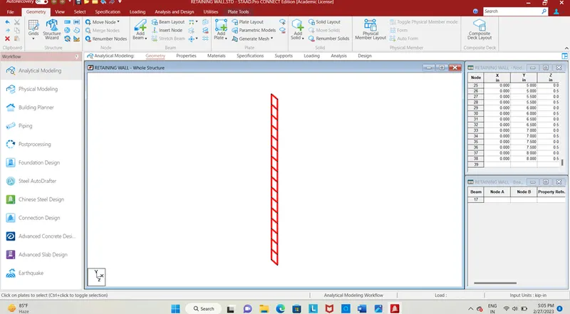
Fig. 5
- Now, select the plate and use trans. repeat command in Y-direction(spacing=0.5, no. of step=15), so that it forms height of the wall which is taken as 8m.
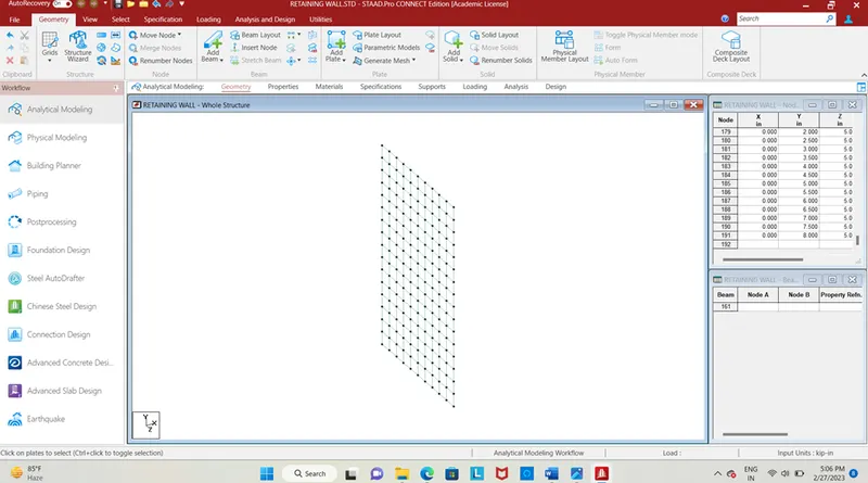
Fig. 6
- Then repeat the translational repeat command to create plate along its length of 5m(spacing=0.5, no. of step=9 ) in Z-direction.
- Provide thickness to the wall as 300mm.
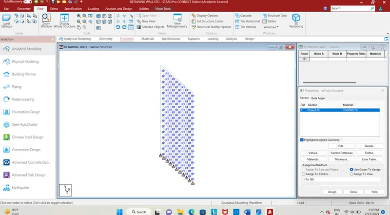
Fig. 7
- Provide fixed support to the wall, select all bottom nodes and go to specification and select fixed support then assign to the selected nodes.
- Now loading is to be provided.
- So the height at which the earth pressure loads to be applied is shown, by using the node to node distance command in utilities tab.
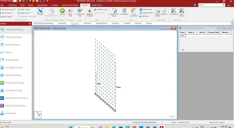
Fig. 8
- The height of 3m and 7m is marked where the pressure due to outer and inner fill will be applied.
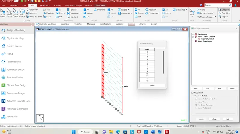
Fig. 9
- Loading is to be applied for the designed wall, add plate loads use hydrostatic load so and the select the plate on which the load will acts.
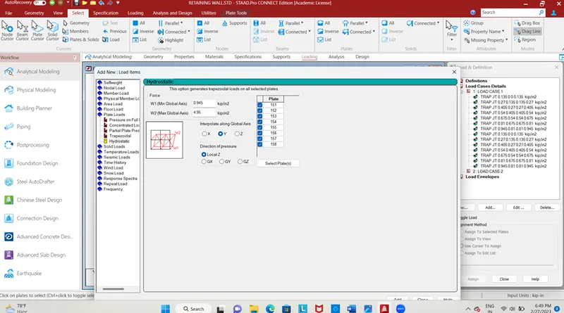
Fig. 10
- Enter the load values as 9.45kn/m2 and select plates up to 3 metres then click on y axis and click add.
- The staad pro will split the load accordingly when we use hydrostatic condition in the plate loads tab which shows the earth pressure loading condition.
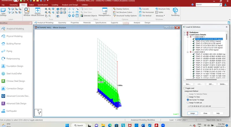
Fig. 11
- The load is applied up to 3 metres shows the earth pressure due to outer fill.
- Select the remaining plates along its row and then apply the load accordingly with its height.
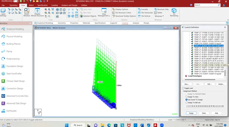
Fig. 12
- Add an another loading of 49.5 kn/m2 which is due to inner fill, for the height of 7m, select the plate up to 7m height and apply the loads on the opposite direction of previous load.
- using the hydrostatic load condition the staad pro will split the load accordingly with its height and select the remaining plates along its row and apply the load.
- After loading save the file and click run analysis command for the analysing.
RESULT :
- After analysis, click on the post processing command to check for plate stresses.
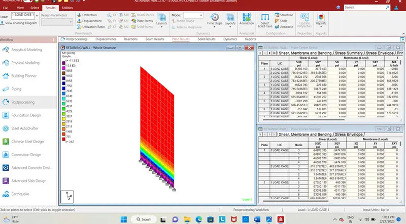
Fig. 13
- The above contour image shows the maximum and minimum of moment and shear values along x direction, the maximum earth pressure acts on the bottom part, where at top minimal amount of pressure acts.
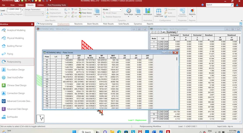
Fig. 14
- The above image shows the reports of bending moment from high to low.