Week 6 Challenge
Aim and Introduction:
- To calculate the pipe load acting on the bridge.
- The pipe load comes under the category of utility loads.
- The utility loads are
- Electrical lamp post, Diection banner loads
- Traffic signal post, Rain water drain pipe
- Pipe loads
- collision and other live loads.
- The Electrical, Mechanical, Architectural elements are considered to be utility loads.
- In this challenge, we are going to design a bridge that carries a pipe of 200mm and 700mm diameter, and to calculate the pipe's self weight and live load of liquid carried by pipe which may be water, oil, gas, or any other kind of chemicals.
Procedure:
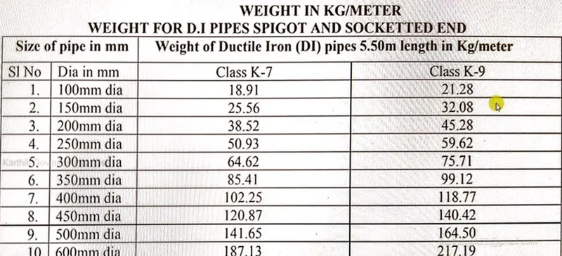
Fig. 1
- The self-weight of the pipe and live load due to liquid in pipe is to be calculated as:
pipe type= class K9 DI pipe.
Liquid= water
Span, L=24m
Self weight of DI pipe,
For 700mm dia and class K9 weight= 217.19kg/m
= 0.217KN/m
For 24m span, W= 0.217*24= 5.208 KN
Live load in DI pipe,
The load due to water in pipe= Area*unit weight of liquid
= 3.14/4 * (0.7)^2 * 10
= 3.848 KN/m
Total load = self weight of DI pipe+ live load in pipe = (0.217+3.848) KN/m = 4.065 KN/m
Self weight of DI pipe,
For 200mm dia pipe and K9 weight = 45.28kg/m = 0.045 KN/m
For 24m length span, W= 0.045*24 = 1.08 KN/m
Live load in DI pipe,
The load due to water in pipe = Area * Unit weight of water
= 3.14/4 * (0.2) ^2 * 10 = 0.314 KN/m
The load = self weight of DI pipe + Live load = (0.045+0.314)KN/m = 0.359 KN/m
Now, these two pipe loads will act on the bridge and will analyse it in the staad pro.
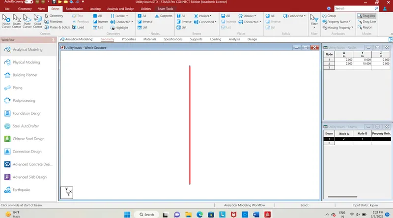
Fig. 2
- Enters the node (0,0,0) , (0,10,0) and by using add beam command pier is formed.
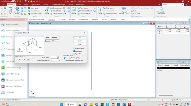
Fig. 3
- Using trans. repeat command in Z-direction, no. of step 1, at the spacing of 3m, width of the bridge is formed.
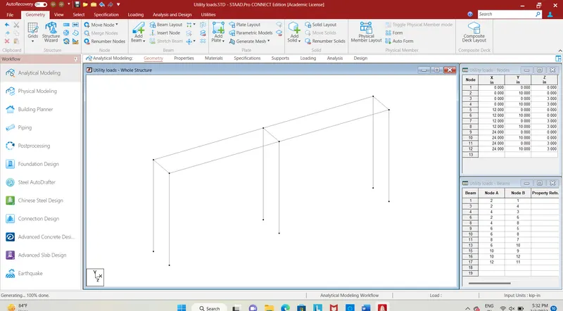
Fig. 4
- By selecting whole structure, we use trans. repeat command in X-direction, no. of step 2 , at the spacing of 12m, which is span length, bridge structure is formed.
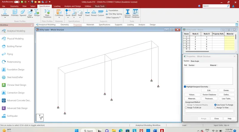
Fig. 5
- By selecting all bottom nodes, we assign the fixed support to the piers.
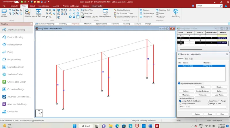
Fig. 6
- we provide the property to the piers by selecting piers and go to specification selecting rectangular section (1.5*1.5)m and assigned to the selected beams.
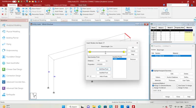
Fig. 7
- We insert two nodes in the cross beam at the distance of 1.64m for 200mm dia pipe and at the distance of 2.0m for 700mm dia pipe.
- go to geometry select insert node, enter the distance and click on add new point.
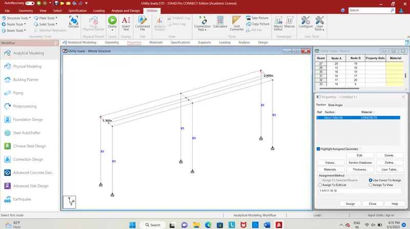
Fig. 8
- Now, with the help of add beam command, join the nodes along length.
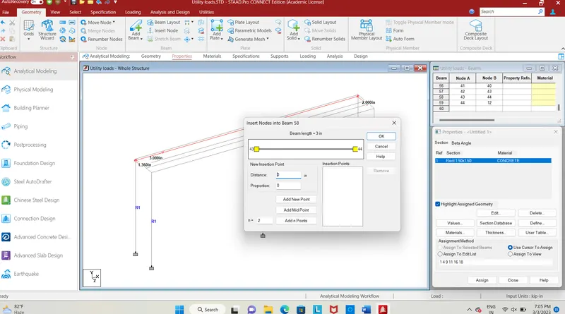
Fig. 9
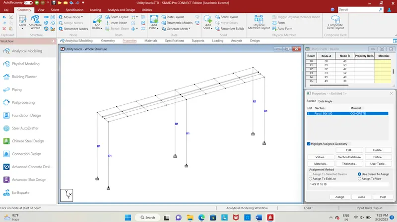
Fig. 10
- We insert the node in the cross beam at the distance of 1.5m for the bracings, now using add beam command we connect the nodes in longitudinal direction.
- Insert nodes for creating the bottom chord bracing as per dimensions given in question repeat the same procedure for adding nodes to all beams
- create the nodes in longitudinal beam at a spacing of 3 m each and add them at both the side.
- 200m dia and 700m dia pipe were also added.
- The cross girders have been created.
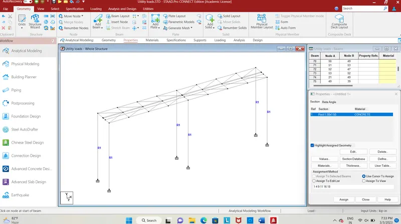
Fig. 11
- Connect the nodes by using add beam command-click on the corner node, connect it at the centre node and connect again at the corner that forms an arrow-like beam.
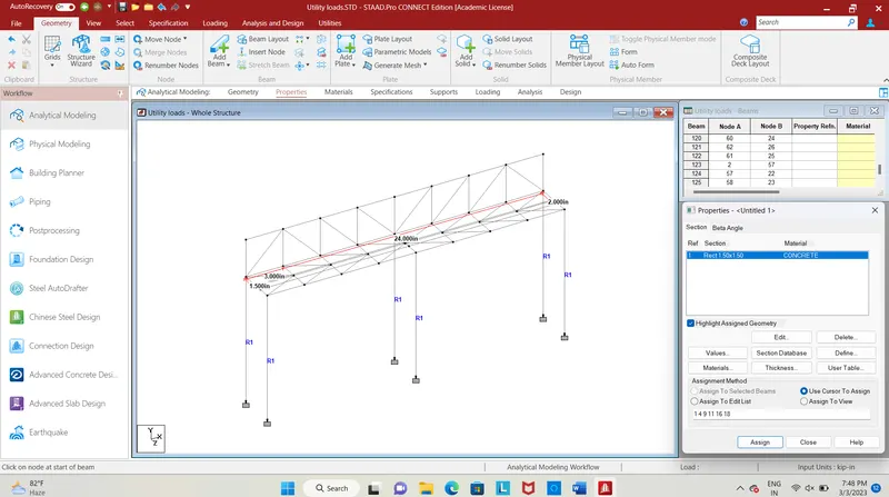
Fig. 12
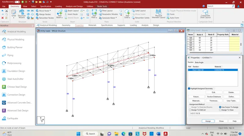
Fig. 13
- Selecting nodes of main beam and Using translational repeat command in the y-direction at a distance of 3m and click on the link steps, provide the required spacing and no of steps.
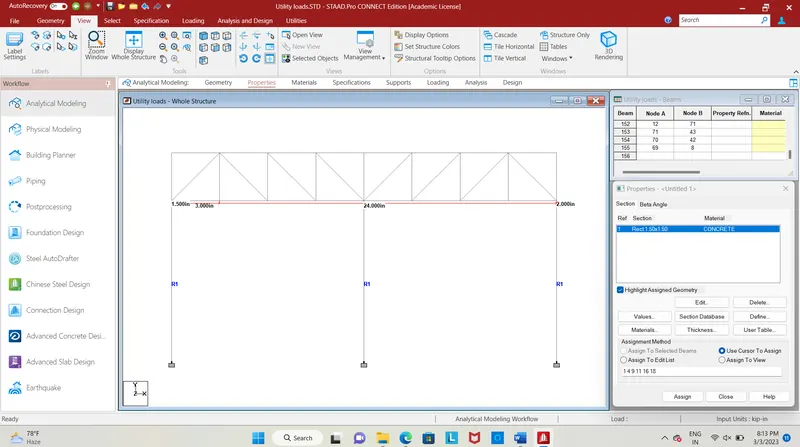
Fig. 14
- This fig shows the longitudinal section of girders.
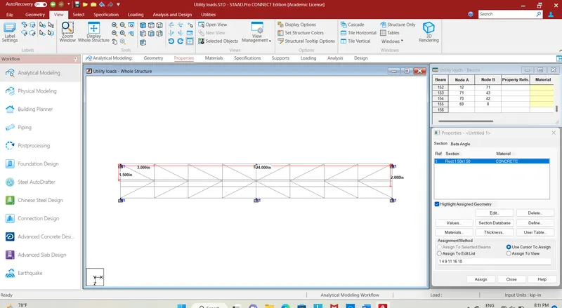
Fig. 15
- This fig shows the bottom chord bracing.
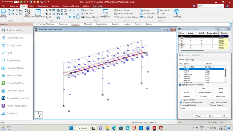
Fig. 16
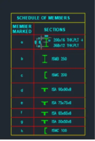
Fig. 17
- The property has been assigned to bottom chord bracings and the girders, according to the given figure.
- circular sections 200 and 700 mm had been assigned to the pipe.
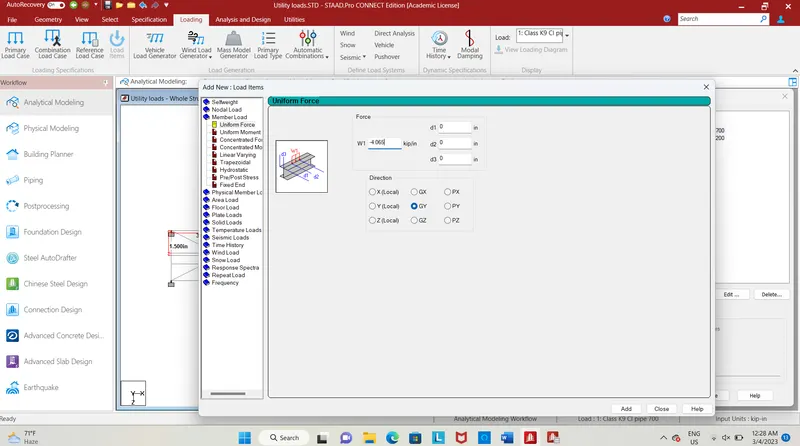
Fig. 18
- Now loading is needed to be added, click on load case details add it as member load by giving uniform force.
- Enter the calculated value and use the minus symbol to indicate the load acting downwards, click on the global y-direction then click add apply it to the 700mm dia pipe.
- Now enter the loading for 200mm dia pipe, use minus symbol to indicate the load acting downwards.
- click on global y direction and add it.
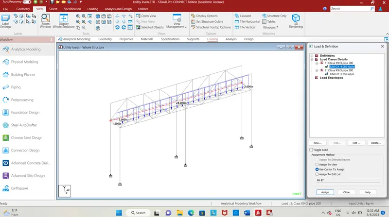
Fig. 19
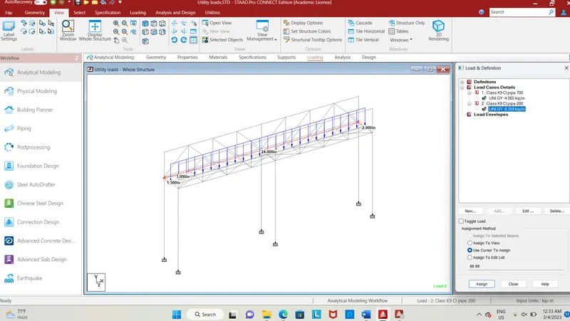
Fig. 20
- The above two images shows the loading diagram for both the pipes.
- And also self weight is need to be added click loading in the load cases details add self weight use factor 1 in the y direction.
- after loading click on post processing analysis to enter the into analysis tab.
Results :
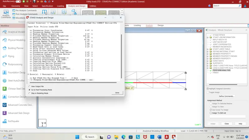
Fig. 21
- Click on the run analysis command in analysis and design command to check with errors, after that click on post-processing mode to analyze the structural behaviour due to pipe load.
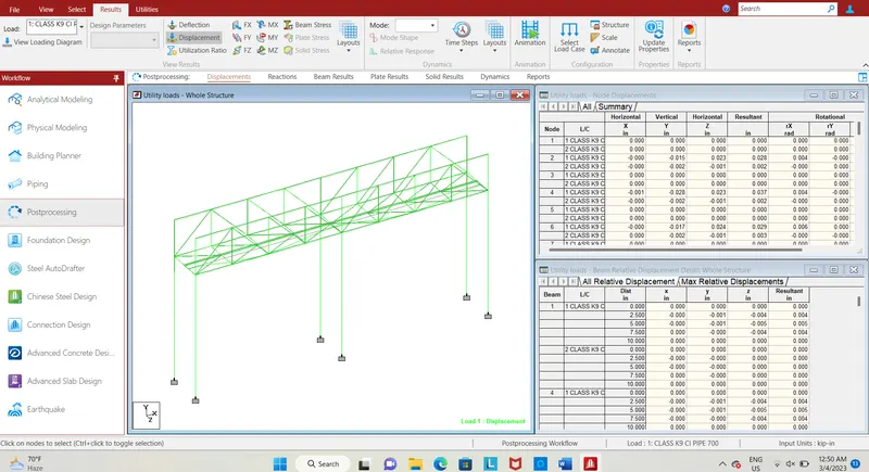
Fig. 22
- The fig. shows the displacement of member due to load of 700mm dia pipe.
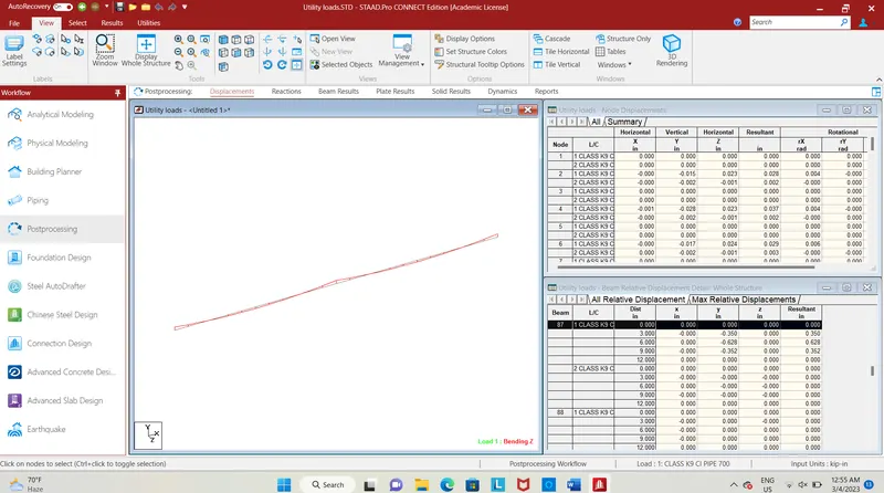
Fig. 23
- The fig. shows the Bending moment in z direction due to 700mm dia pipe load.
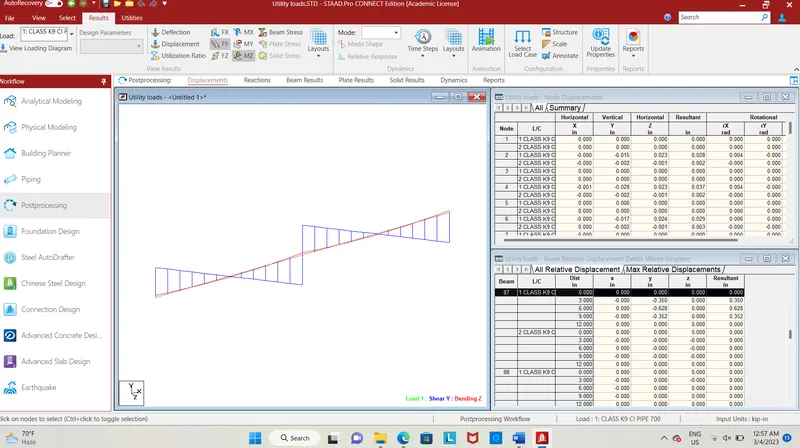
Fig. 24
- The fig. shows the Shear diagram in y direction in 700mm dia pipe.
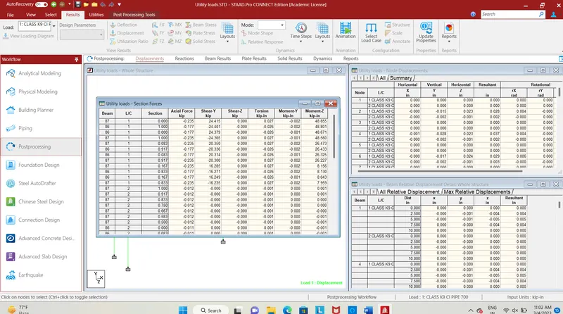
Fig. 25
- The fig. shows the report of bending moment in Z from high to low due to class K9 di pipe load.