Week 5 Challenge
- Generate manual wind loading in the design report based IS code as per the following input
- Basic wind speed = 39m/s
- Terrain category 2
A) AIM: TO GENERATE MANUAL WIND LOADING IN THE DESIGN REPORT BASED ON IS CODE AND MENTIONED INPUTS.
TOOLS/APPARATUS REQUIRED:
EXCEL
IS CODEBOOK(875 P3)
DIMENSION
CALCULATOR
property window( for roof angle)
PROCEDURE:
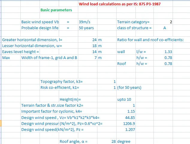
1) primarily as we are going to calculate wind loads in an excel sheet so let us open the excel sheet.
2) we make use of IS code for assigning some values so arrange IS 875(part-3)
3) Now let us assign the given parameters in the excel sheet i.e
- Basic wind speed = 39m/s
- Terrain category 2
apart from this let us also assign some other factors that are
probable design life of structure-50 years (assumption)
class of structure -A
4) apart from the above-mentioned properties let us assign some other properties that include the physical properties of the model
greater horizontal dimension, the lesser horizontal dimension of the structure, eaves level height,
and width of the structure
5) now from these dimensions let us calculate the ratio for wall & roof coefficient and with those coefficients, we can calculate A, B, C, D
6) from these details and as per IS code calculate coefficients
k1 from the design period
k2 terrain, height & string size factor
k3 topographic factor
k4 factor-related to cyclone occurrence
7) from these coefficients and details we can compute design wind speed and design wind pressure
by substituting in the formula
Vz=vb*k1*k2*k3*k4 &
pz=o.6*Vz2 (convert it from n/mm2 to KN/m2)
8)then we have to calculate the wind loads in both the X and Y direction with the help of cpi
and calculate
- External pressure coefficients.
- Internal pressure coefficients.
- Net pressure coefficients.
- Design wind pressure for the wall.
9)we have to apply factor for safety let us consider it as 1.05 so we have to multiply the load we get by 1.05
10)By multiplying the factor we get to know the loading to be applied on the wall face(+-Cpi) we get the values of wind loads that are to be applied on the walls of the members.
11)similarly we model wind loads for roof in the same way as for the faces A, B, C, D but instead of ratios we make use of roof angle.
RESULT:
we have Generate manual wind loading in the design report based IS code as per the following input
- Basic wind speed = 39m/s
- Terrain category 2
and we calculated values of the wind load
for face A, C
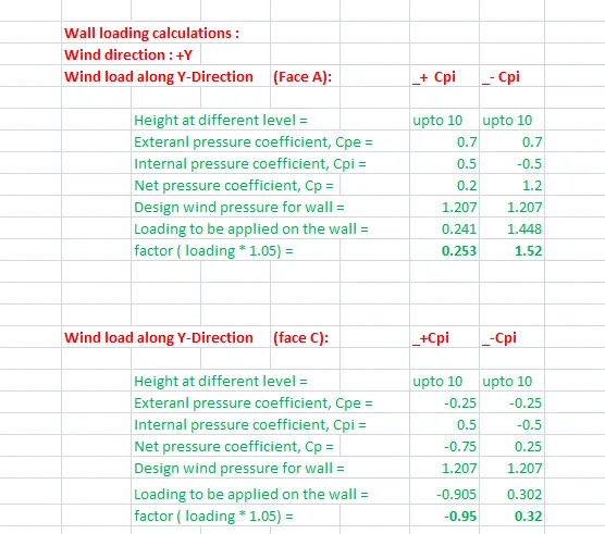
for face B & D
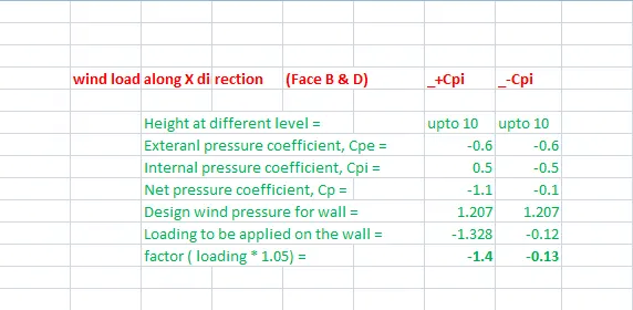
For roof
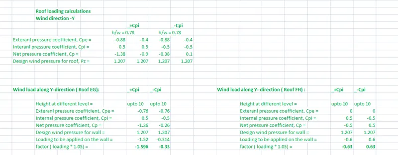
2. Based on the above calculation apply the loadings on the model
AIM: TO APPLY THE WIND LOADINGS ON THE MODEL(WALLS,ROOF) FROM THE ABOVE CALCULATION
TOOLS/REQUIRED:
FILE
OPEN
SAVE
LOAD
LOAD CAES
VALIDATE
AREA LOAD
PROPERTY WINDOW
PROJECT BROWSER
FRAMES
SEEN CONTENT
WIND LOAD
SAVE
PROCEDURE:
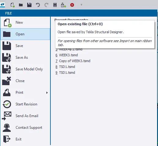
1. Open the saved file in Tekla software using the open tab present in File ion.
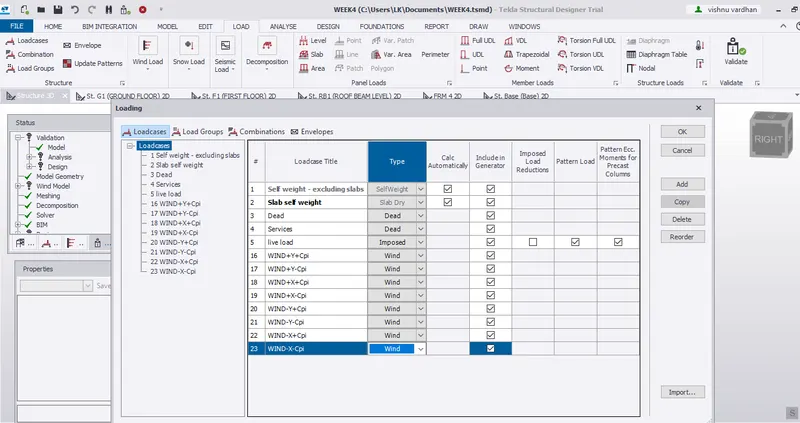
2. Then select load cases icon present in load toolbar a window appears.
3.then click on add and name it as wind+Y+Cpi and assign it to wind load.
4.Similarly add 3 more loads in the similar way and assign the type of load as wind load.
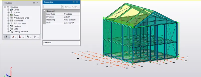
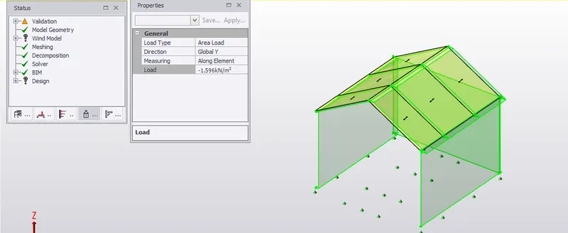
5) now let us select a load, say WIND+Y+Cpi at the bottom down box after selecting the load option and select the area load option available and modify its global direction to global y-direction and from our calculated values and place the area load
6. based on the sign of the applying load we will know whether the load is acting away from the member or towards the member then accordingly apply loads. based on the sign of the applying load we will know whether the load is acting away from the member or towards the member then accordingly apply loads
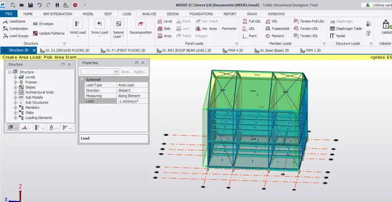
7. For this let us make use of frames, for frames we have to select frames from the model tab
8. the frames modeled can be accessed using the project browser.
9. From calculation we know after 10 m height the constants vary, so we can make use of the patch loading option available in the loading option.
10. similarly, we can do it for the wind loads in the remaining directions for the remaining faces.
11. validate the model after each step.
12. for a more specified view we can make use of seen content.
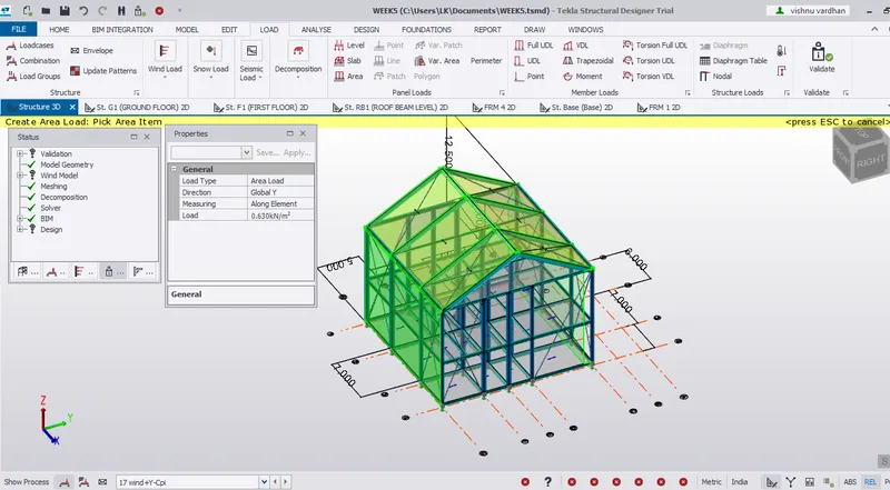
13. for the roof we have to create new load cases and apply the area load on the roof with the values calculated by selecting the type of load from the bottom box.
RESULT:
Based on the calculation done, we have applied the wind loadings on the faces of the model as well as for the roof
- On a separate model generate wind loading using wind wizard
AIM: To generate wind loading using wind wizard
TOOLS REQUIRED:
FILE
NEW
COLUMN
BEAM
MANAGE PROPERTY SET
SLAB
PROPERTY WINDOW
PROJECT BROWSER
GRID
CONSTRUCTION LEVEL
VALIDATE
SEEN CONTENT
WALL PANELS
ROOF PANELS
LOADS
LOAD CASES
AREA LOAD
WIND WIZARD
PROCEDURE:
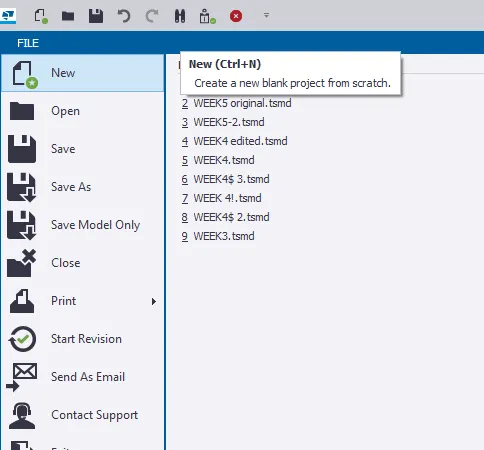
1. Open the Tekla software and select a new option from the file menu.
2. Then draw construction levels heights and grid lines from the model tab according to the model.
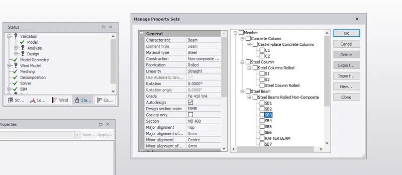
3.Now select column icon from the model toolbar and locate beams according to plan and make use of manage property sets option for characteristics of beams, column
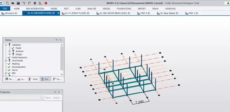
firstly model concrete column and then model steel column
4. then click on the beam option from the model icon and model beams.
5. we can make use of the property window for modifying properites using property window.
6.validate after each step
7.then design rafter beams option after selecting manage property set and selecting a particular property.
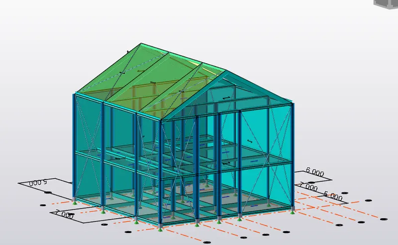
8.then model roof and wind panels from the icon present in the model toolbar.
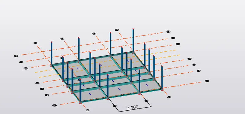
9. now let us model the slab by selecting the slab option in the model toolbar.
10. select load cases option from the loading tab and add dead load and live load from the dialog box appearing
11. from the bottom menu select as dead load and apply dead load as per IS CODE.
12.similarly apply live load as per IS code.
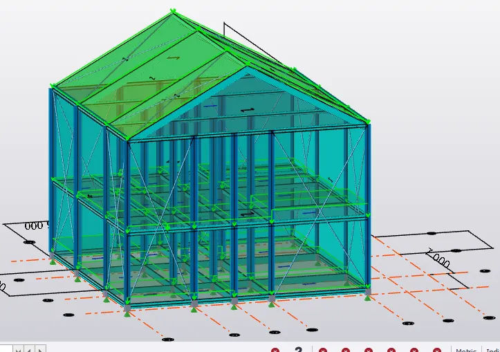
13. Now let us select the wind wizard icon from the load toolbar
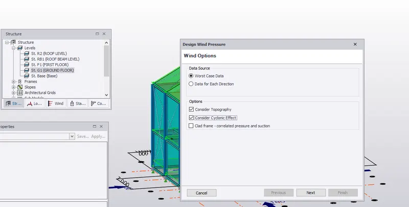
14. a dialog box appears select data sources as worst-case data and some options are available select consider topography, consider cyclone effect.
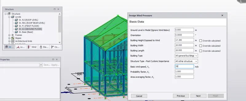
15. then a table appears with some data already assigned from the model and we can assign or alter some properties, let us assign wind speed as 39, and we can change other
data as well by simply clicking override calculation.
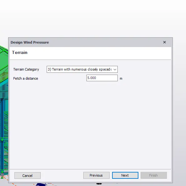
16.then it asks regarding terrain category let us select terrain with numerous closely spaced obstructions and assign a value for fetch distance as 5m then click next
18. it asks for details regarding topography assign them and click next.
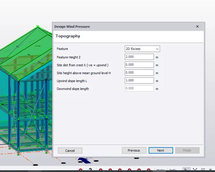
19. after clicking next results are displaced
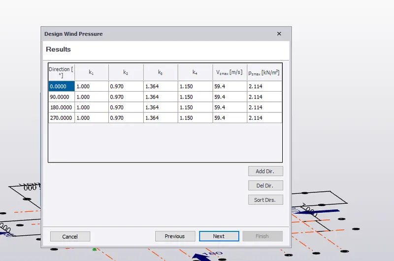
then click next once again
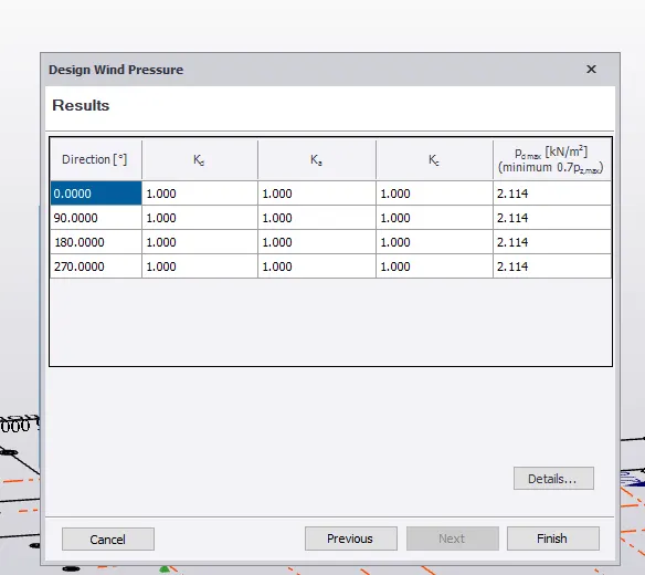
final results are displayed then simply click finish, we have successfully applied wind loads to the model.
RESULTS: We have successfully applied wind loads to our model with the help of the wind wizard option which automatically calculates wind load by simply assigning values regarding topography or measurements to it
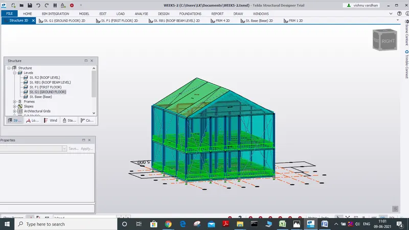
the final output is
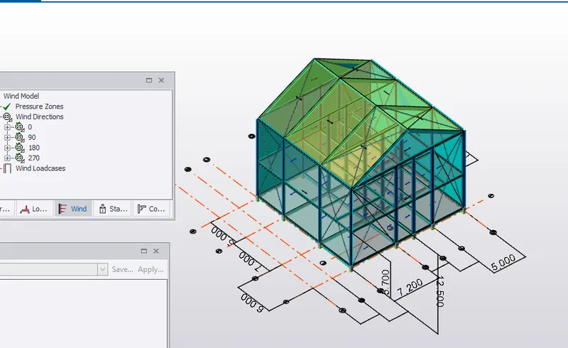
and wind wizard option can be seen in the project window and can be accessed from there.