Bending of iPhone Using Ansys Workbench
OBJECTIVE
- To import the iPhone model.
- To import the required material properties.
- To assign the required material, and contacts.
- To mesh the model.
- To apply the boundary condition.
- To collect the results and interpret.
PROCEDURE
In this work, there were two cases to analyze. In the first case, the iPhone was bent from one side, while in the second case, it was bent from the middle. The simulation seems to be static non-linear, therefore, it had to solve using the Static Structural module of Ansys. Next, the material had to define before proceeding further. Using Engineering data, all the required materials viz. structural steel, polyethylene, aluminum alloy, and glass were imported.
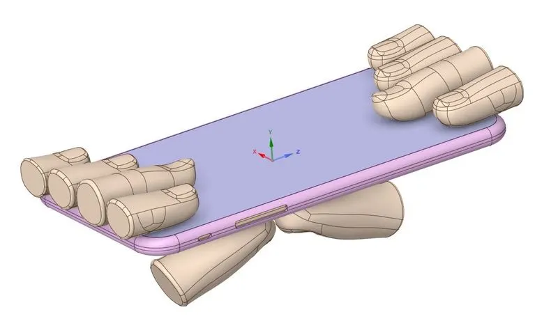
Figure 1: iPhone with fingers model in Ansys GUI.
The Mesh section of the Static Structural module was opened. In that, the material of the display was set to glass, the material of the body of the iPhone was set to aluminum alloy, and the material of the internal body of the phone was set to polyethylene. The stiffness behavior of all the fingers except one thumb was set to rigid.
Next, a frictionless contact was set between the contacting faces of fingers and the phone. A fixed joint was created for the fingers, and the translational joint was created for the thumbs.
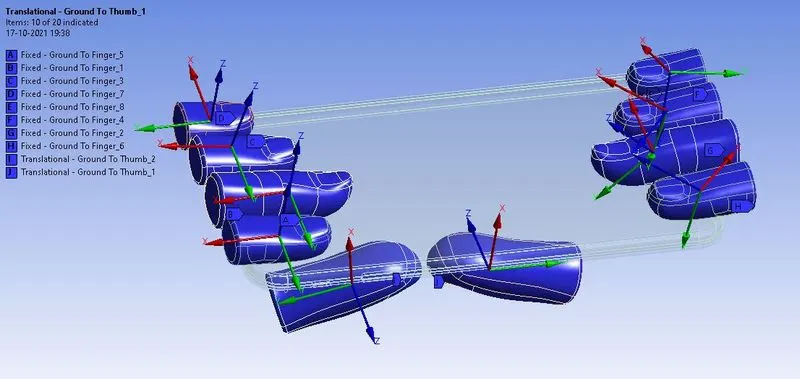
Figure 2: Fixed joint for fingers and translational joint for thumbs.
Next, the mesh was created for the model, as shown in the figure below.
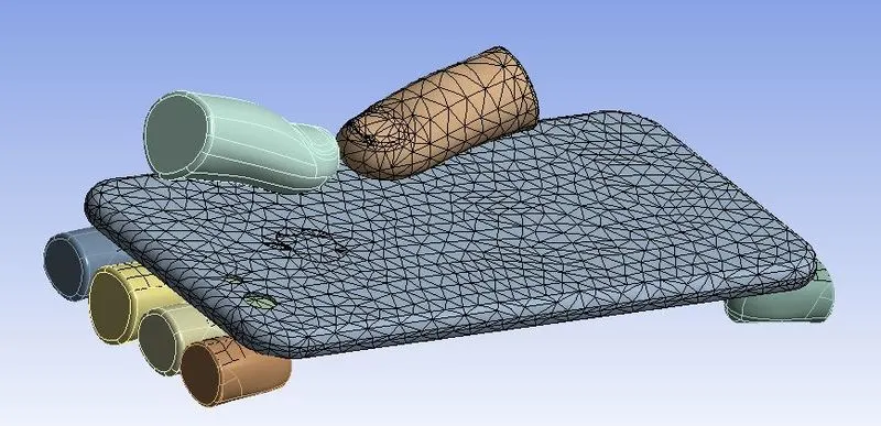
Figure 3: Meshing of the model.
The analysis was solved in 8 steps. In boundary condition, the internal body of the phone was fixed, the displacement was constrained to move in y-axis only for the phone, and the displacement of 8 mm (in steps) was applied to the thumbs as shown in the figure.
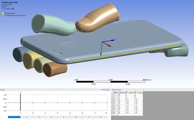
Figure 4: Displacement was constrained to move in y-direction only.
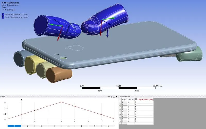
Figure 5: Maximum displacement of 8 mm was given to thumbs.
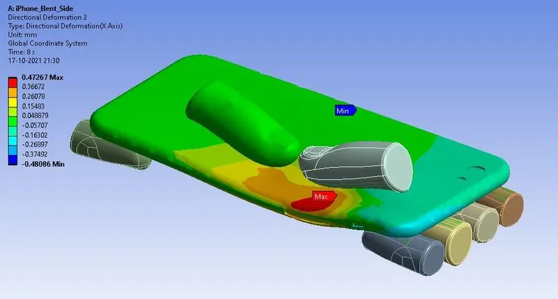
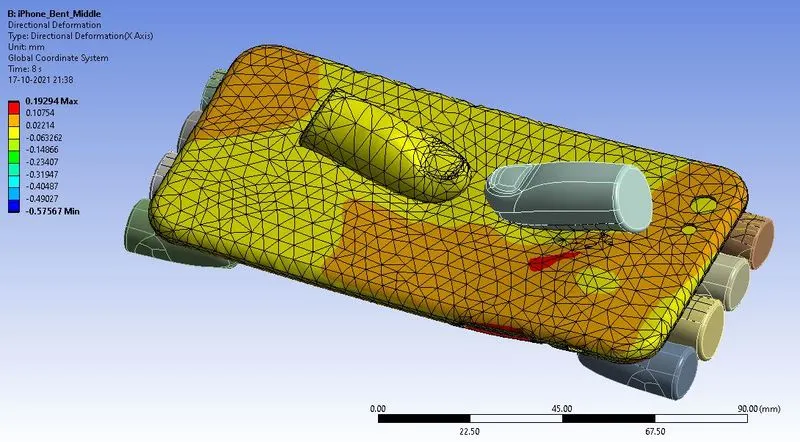
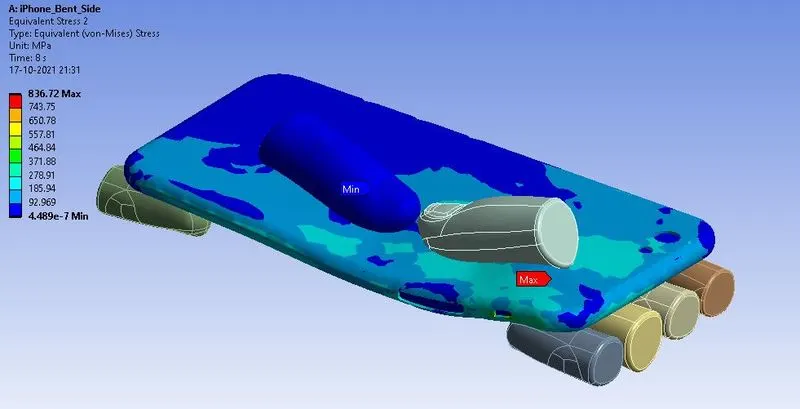
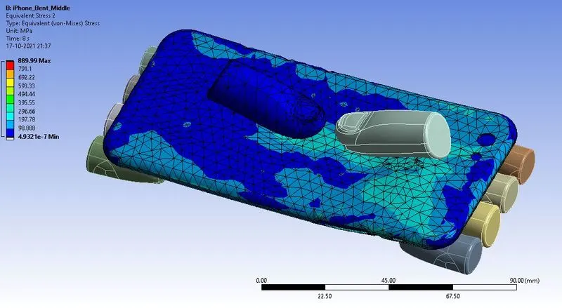
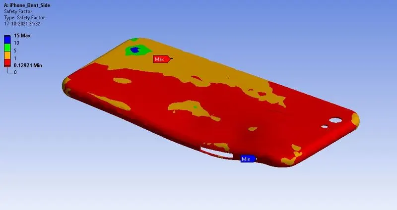
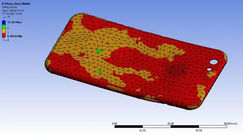
In the solution, the results were requested for the equivalent stress, directional deformation in the phone, and life and FOS of the frame of the phone. All the results are shown in the figures below.
|
CASE A |
CASE B |
|
|
|
|
Figure 6: Directional deformation in the direction parallel to the line of action of displacement. There is maximum deformation of 0.472 mm in case A, while 0.192 in case B. |
|
|
CASE A |
CASE B |
|
|
|
|
Figure 7: Equivalent stress induced in the model. There is maximum stress of 836.72 MPa in case A, and 889.99 MPa in case B. |
|
|
CASE A |
CASE B |
|
|
|
|
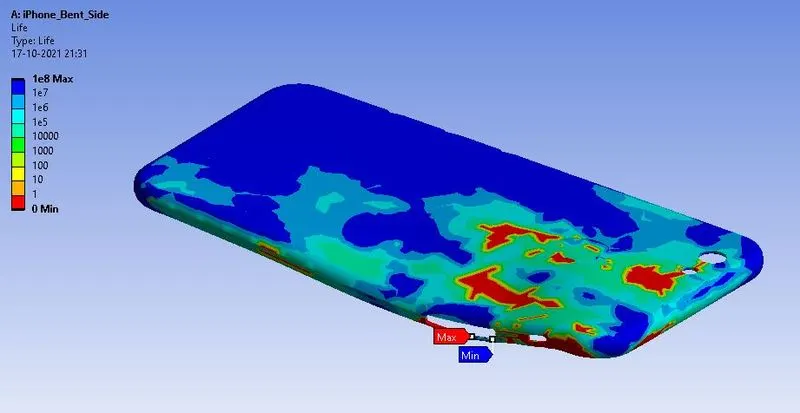
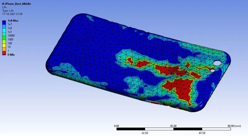
Figure 8: Life of the frame of the model. The surface area that can survive for more time can be observed more in case A compared to case B. |
|
|
CASE A |
CASE B |
|
|
|
|
Figure 9: Factor of safety in the frame of the model. |
|
CONCLUSION
In this work, an attempt was made to simulate the bending of an iPhone. After performing the analysis for two different cases, it is observed that when phone is bent from one side it undergoes comparatively larger deformation of 0.47 mm. In case B it was only 0.19 mm. However, the stress induced in case B was 889 MPa, while in case A it was 836 MPa. Also, the surface are with more life is comparably more in case A than in case B. Thus, it can be conclude that though both of the case is undesirable for the phone, the case B, where the phone was bent from middle, will damage more to the model compared to case A, where the phone was bent from one side.