Week 5 Bending of iPhone
Objective:
-
To simulate the bending of iPhone as per the given cases below
Case 1: Simulate the model as it is given in the video
Case 2: Move the bottom fingers from their defined position to the given position X= 22.5mm & Z= 10mm and obtain the results for the simulation. Also define the S-N curve for the Aluminium Alloy material as per values given below and determine the fatigue life results for the same.
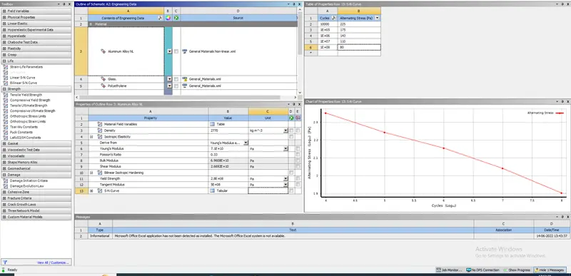
Stress, MPa Number of Cycles, N 225 10000 175 100000 143 1000000 110 10000000 80 100000000 Require Results and Deliverables:
- Obtain the directional deformation for the model
- Factor of Aluminium Alloy NL
- Life of the Aluminium alloy for the case
- Compare the results and present with the conclusion.
Procedure:
Step 1: Engineering Data
- Add Aluminum NL material to drop down list of materials.
- Add poyethylene to the list from list of general materials
- Duplicate this material and rename it glass. Add the following specification to the material.
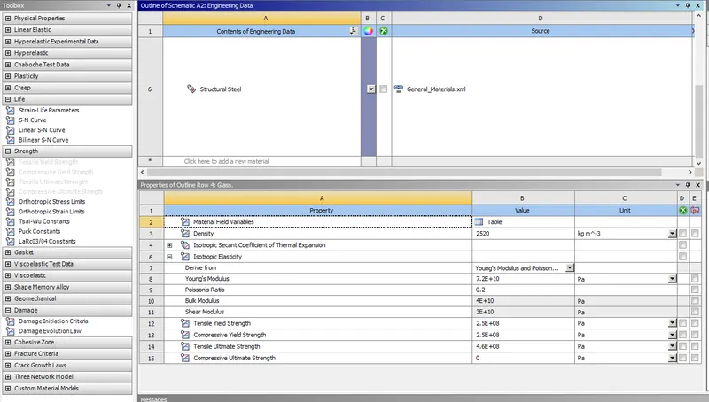
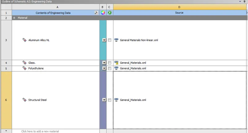
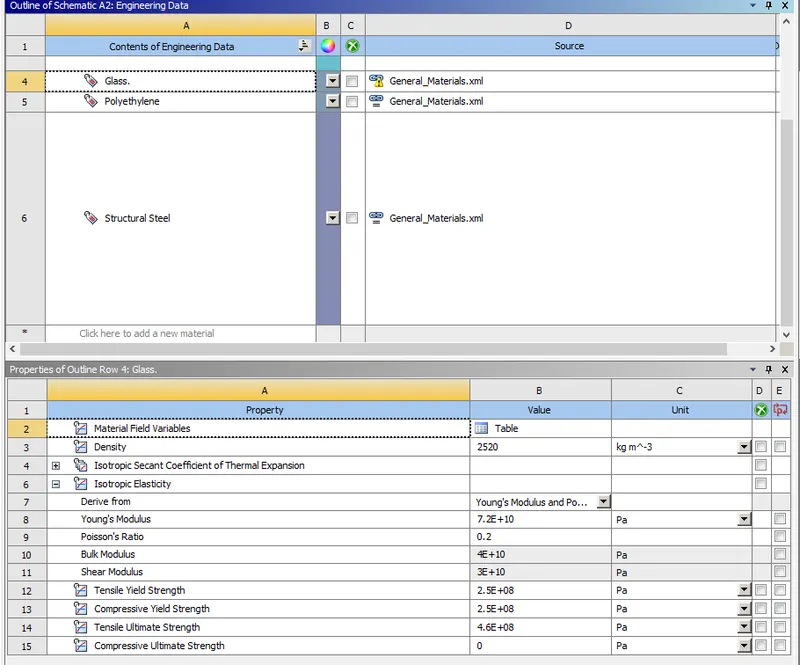
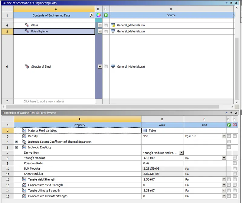
- Check for the above four listed materials in your model tab.
For Case 2: Insert the SN curve and add the following listed data.
Step 2: Geometry
- Right click on geometry and Import the Skill_Lync_Iphone_Bending.x_t extension file
- Rename the Static Structural tab as Iphone Bending.
- Update the Static Structural tab and proceed to edit geometry in spaceclaim.
- Check for the Surface limit if you have Ansys student version and merge some under repair tab if you need to reduce surface count.
- update the Model tab and open click Edit.
- For case 2 open spaceclaim under Move tab enter XYZ coordinate to move thumb L and R relative to give cordinates by amount X= 22.5mm & Z= 10mm.
Step 3: Model and Meshing
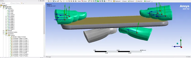
- Open Model and under geometry assign names according to convenience for better understanding.
- Rename geometries as Display, Frame,Inside, Thumb R(Pushing Finger), Thumb L, and rest all as Finger 1-8.
- Assign Aluminum NL material to Frame.
- Assign poyethylene material to Inside.
- Assign Glass material to Display.
Step 4: Connections
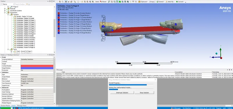
- Contacts:- Define the contact faces between Display to frame as Bonded type of contact.
- Define the rest of contacts as Frictionless.
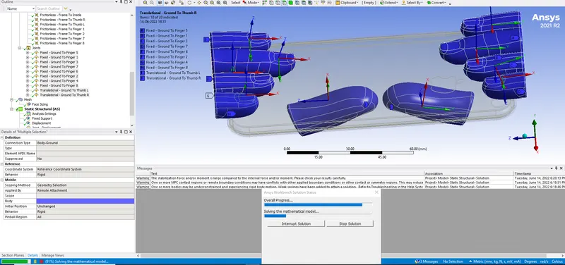
- Insert Fixed Body to ground Joint for Finger 1-8.
- Insert Translational Joint Body to Ground for both the thumbs.
- insert face sizing for the contact part of thumb and frame as shown below.
- Use Augmented Lagrange as Formulation method.
Step 5: Setup
- Insert 8 number of steps for analysis.
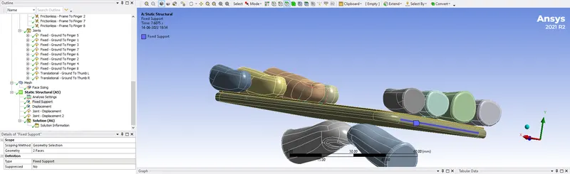
- Insert Fixed support for edge face of inside body as shown.
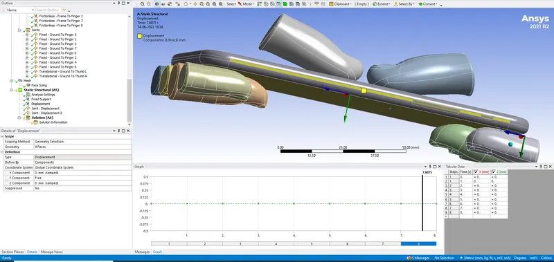
- Insert displacement for 4 side face of frame to lock its movemnt in X and Z direction
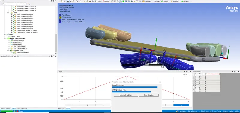
- Insert Joint load for Thumb L defined by displacement type with tabular data of displacement from 0,2,4,6,8,6,4,2 mm with retraction effect.
- Similarly duplicate this joint and attach this to Thumb R body.
Results:
CASE1
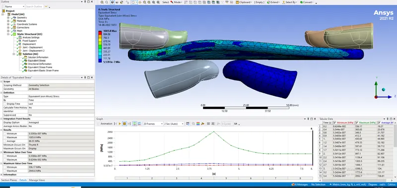
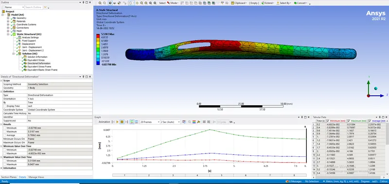
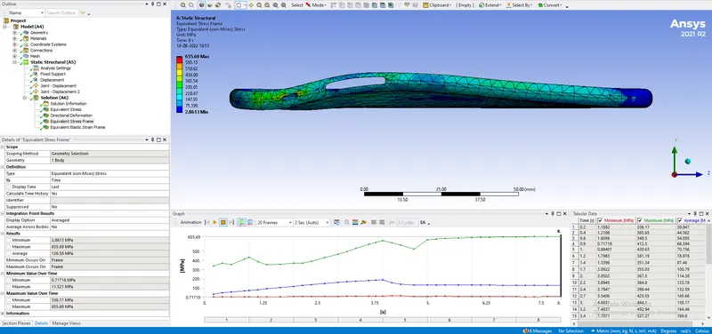
CASE2
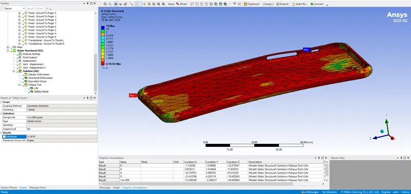
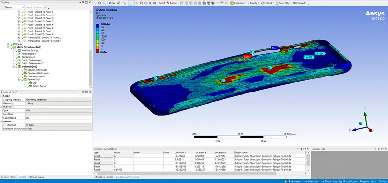
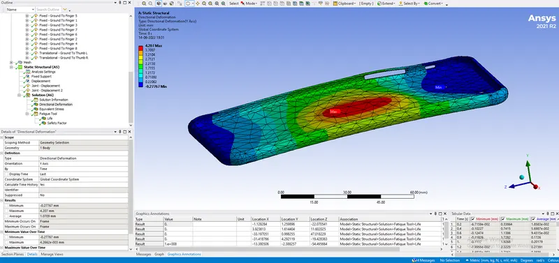
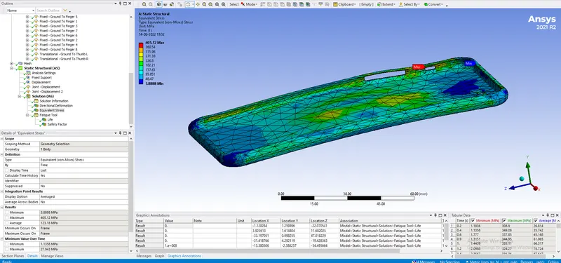
- Comparison of case 1 & 2 results:
| Case # |
Equivalent Stress Frame Aluminum alloy NL |
Directional deformation for the model Y-dir |
Factor of Safety- Aluminium Alloy NL (minimum) |
Life of the Aluminium alloy |
| Units | MPa | mm | Cycles | |
| Case 1 | 655.69 | 5.5187 | NA | NA |
| Case 2 | 405.12 | 4.207 | 0.19747 | 1e+008 |
Conclusion:
From results comparison we see that stresses produced (Frame body only) in case 1 are higher than case 2 where the frame is bent from central area. The Life cycle of part where frame is bent shows the results as 0 because the material is bent and damaged. Corresponding probes indicate the cycle life of frame in parts where it is damaged and not damaged (1e+008 cycles in parts where its not damaged and 0 cycles where its damaged). The Factor of safety has dropped below 1 as the frame is damaged and can take no more loading.